Table of Contents
Advertisement
Quick Links
480 Platinum Pro Series
Commercial Contractor
Grade Multimeter
True RMS
#61-482
Symbols in this Manual
This symbol indicates where cautionary or other
information is found in the manual.
Fuse
Battery
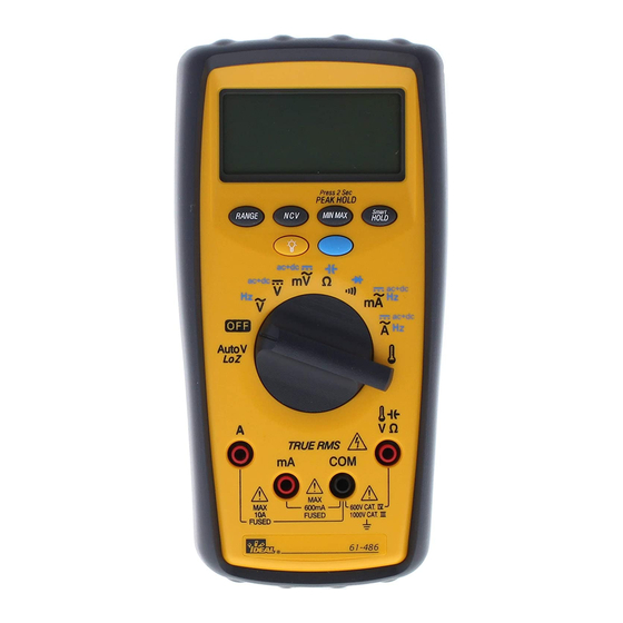
Refer to Figure 1 and to the following numbered steps to
familiarize yourself with the meter's front panel controls
and connectors.
True RMS
1
9
10
8
7
11
12
2
4
3
5
6
2
Advertisement
Table of Contents

Subscribe to Our Youtube Channel
Related Manuals for IDEAL ND 2366-1


Summary of Contents for IDEAL ND 2366-1
- Page 1 #61-482 Symbols in this Manual This symbol indicates where cautionary or other information is found in the manual. Fuse Battery Refer to Figure 1 and to the following numbered steps to 480 Platinum Pro Series familiarize yourself with the meter’s front panel controls Commercial Contractor and connectors.
- Page 2 1. Digital Display – The digital display has 4000 counts WARNING! LCD readout with 82 segments analog bar graph, auto 1. DO NOT UNDER ANY CIRCUMSTANCES EXCEED THESE polarity, decimal point, “ ” AC, DC RANGE, RATINGS: APO and unit annunciators. •...
- Page 3 Overload Protection True RMS AC Volt Circuit Connection: Function Overload Protection VAC & VDC 1000V AAC & ADC 1A/500V 16A/500V Ohms ( ) 600VAC/600VDC Diode 600VAC/600VDC Continuity 600VAC/600VDC True RMS Unit of Measure Multipliers For your reference, the following symbols are often used to make measurement easier: Symbol Verbal...
-
Page 4: Circuit Connection
True RMS AC Current DC Volts Circuit Connection: Circuit Connection: True RMS True RMS Range Resolution Accuracy Voltage Range Resolution Max Display Accuracy Display Burden 400mV 100µV 400.0 ±(0.25% +5) 40mA 10µA 40.00 ±(2.0% +5) 200mV max 4.000 ±(0.4% +1) 400mA 0.1mA 400.0... - Page 5 DC Current Frequency/RPM Circuit Connection: Circuit Connection: True RMS True RMS Range Resolution Accuracy Voltage Range Resolution Sensitivity Accuracy Display Burden 4.0KHz/40KRPM 1Hz/30RPM 100mV rms* Frequency: 40mA 10µA 40.00 ±(0.6% +2) 200mVmax 40KHz/400KRPM 10Hz/300RPM 0.01% ±1 digit 400mA 0.1mA 400.0 ±(0.7% +2) 2Vmax 400KHz/4MRPM...
- Page 6 Resistance (Ohms) Range Guide for Ohms ( ): 400 = Meter indicates actual resistance = Multiply meter display reading by 1,000 to Circuit Connection: acquire actual resistance. 40k = Multiply meter display reading by 1,000 to acquire actual resistance. 400k = Multiply meter display reading by 1,000 to acquire actual resistance.
- Page 7 Resistor Color Code Table Temperature Tolerance Color Digit Digit Multiplier (Percentage) Black Brown Orange 1,000 Yellow 10,000 Green 100,000 Blue 1,000,000 Violet 10,000,000 Gray 100,000,000 True RMS White 1,000,000,000 Gold +/- 5% Silver +/- 10% No Color +/- 20% Example: Temperature Accuracy Temperature Accuracy...
- Page 8 Diode Testing Capacitance Circuit Connection: True RMS True RMS Function Resolution Accuracy Max.Test Max.Open Range Resolution Accuracy Current Circuit Voltage ±(3% + 10 digits) 40nF 10pF +(1.5% +5)* 1.5mA 400nF 100pF ±(2% + 6 digits) * For 0.4V to 0.8V. 4µF Overload Protection: 600V rms max 40µF...
-
Page 9: Continuity Check
Continuity Check Peak Hold Measurements Circuit Connection: True RMS True RMS Function Range Accuracy Function Range Accuracy DC Voltage 400mV Unspecified AC Voltage 400mV Unspecified To Verify Continuity: ±(1.5% +300) ±(1.5% +300) A continuity test ensures that all circuit connections are intact. ±(1.5% +60) ±(1.5% +60) 1. - Page 10 Accessories General Specifications LCD Display: 4000 count maximum reading Bar Graph Display: 82 segment analog bar graph Polarity Indication: Automatic, negative indicated, positive implied Overrange Indication: “OL” or “-OL” Low Battery Indication: “ ” when the battery voltage drops below operating voltage Size (WxHxD): 88mm x 180mm x 33.5mm...
-
Page 11: Maintenance
Maintenance Fuse Replacement 1. Remove the test leads from the front terminals and turn the Warning meter off. To avoid electrical shock, remove test lead before opening the 2. Remove the screw from the battery cover and lift to remove. cover. -
Page 12: Lifetime Limited Warranty
Any implied warranties arising out of the sale of an IDEAL product, including but not limited to implied warranties of merchantability and fitness for a particular purpose, are limited to the above.
Need help?
Do you have a question about the ND 2366-1 and is the answer not in the manual?
Questions and answers