Advertisement
Available languages
Available languages
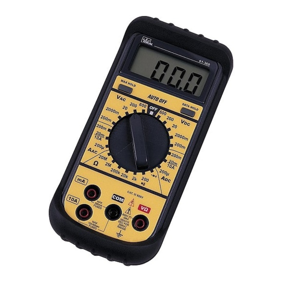
IDEAL Test Pro
360 Series Multimeter
#61-360
®
WARNING!
1.
DO NOT UNDER ANY CIRCUMSTANCES EXCEED
THESE RATINGS:
- Voltage is not to exceed 600V AC or DC.
- Resistance, Capacitance, Logic, and Continuity
functions are not to be performed on circuits capable
of delivering greater than 500V AC or DC.
- Current measurements are not to be performed on
circuits capable of delivering greater than 600V AC
on insulated conductors, 250V AC on uninsulated
conductors.
2.
To avoid electrical shock hazards and/or damage to the
meter:
- Do not exceed the voltage ratings for the meter. Use
caution when measuring voltage.
- Do not use during electrical storms. AC power
sources with inductive loads or electrical storms may
result in high voltage. High energy transients can
damage meter and present a dangerous shock hazard.
- Turn off the power to the circuit or device being mea-
sured before taking resistance and capacitance mea-
surements. Fully discharge all capacitors before
measuring.
3.
Ensure meter is in proper working order before using.
Visually inspect meter for damage. Performing a conti-
nuity check can verify proper operation. If the meter
reading goes from overload to zero, this typically means
the meter is in proper working order.
4.
Visually inspect leads for damage before using. Replace
if insulation is damaged or leads appear suspect.
5.
Never ground yourself when taking electrical measure-
ments. Do not touch exposed metal pipes, outlets, fix-
tures, etc. Keep your body isolated from ground by
using dry clothing, rubber shoes, rubber mats, or any
other approved insulating material. Keep your fingers
behind the finger guards on the probes. Work with oth-
ers.
6.
Before beginning all unknown measurements, set meter
to the highest range possible.
Page 2
Advertisement
Table of Contents

Subscribe to Our Youtube Channel
Related Manuals for IDEAL ND 1075-2


Summary of Contents for IDEAL ND 1075-2
- Page 1 - Voltage is not to exceed 600V AC or DC. - Resistance, Capacitance, Logic, and Continuity functions are not to be performed on circuits capable IDEAL Test Pro ® of delivering greater than 500V AC or DC. - Current measurements are not to be performed on...
- Page 2 ND 1075-1 61-360 Instructions 3/9/06 4:51 PM Page 3 AC VOLTAGE WARNING! (cont.) Meter Setup: Circuit Connection: Before breaking a circuit for testing, turn off the power to the circuit. When disconnecting from a circuit, discon- nect the hot lead first, then the common lead. Disconnect the meter from the circuit before turning off any indicator, including motors, transformers,and sole- noids.
- Page 3 ND 1075-1 61-360 Instructions 3/9/06 4:51 PM Page 5 Resistance (Ohms) Meter Setup: Circuit Connection: Function Range Resolution Accuracy DC Voltage 200.0 mV .1 mV ± (0.5% +1) 2000 mV 1 mV ± (0.5% +1) 20.00 V .01 V ± (0.5% +1) 200.0 V .1 V ±...
- Page 4 ND 1075-1 61-360 Instructions 3/9/06 4:51 PM Page 7 To Verify Continuity: Resistor Color Code Table 4. Test for continuity by connecting the meter to the circuit. 5. If the beeper sounds the circuit is complete. Tolerance Color Digit Digit Multiplier (Percentage) Continuity Beeper...
-
Page 5: Diode Testing
ND 1075-1 61-360 Instructions 3/9/06 4:51 PM Page 9 5. Read the forward voltage drop on the digital display: To Measure AC Current (cont.): A good silicon diode will result in a reading around 1. Connect the test leads into the meter inputs as indicated in 0.7 V. - Page 6 ND 1075-1 61-360 Instructions 3/9/06 4:51 PM Page 11 To Use Accessories: To Measure DC Current: Current is measured in amps. For AC Current Clamp: Do not attempt to measure current in circuits capable of 1. Plug test leads into the meter inputs as indicated in dia- delivering greater than 600V.
- Page 7 ND 1075-1 61-360 Instructions 3/9/06 4:51 PM Page 13 Cleaning Case and window General Specifications: Periodically wipe the case with a damp cloth and detergent, Data Hold: “HOLD” button “locks” reading. Any range or func- allow to dry completely before using; do not use abrasives or tion.
-
Page 8: Two Year Limited Warranty
360 Any implied warranties arising out of the sale of an IDEAL prod- uct, including but not limited to implied warranties of mer- chantability and fitness for a particular purpose, are limited to the above. - Page 9 ND 1075-1 61-360 Instructions 3/9/06 4:51 PM Page 17 ¡ADVERTENCIA! (cont.) ¡ADVERTENCIA! Antes de interrumpir un circuito para probar, desconecte 1. NO EXCEDA ESTOS VALORES EN NINGUNA CIRCUNSTAN- CIA : la corriente del circuito. Al desconectar un circuito, - El voltaje no debe exceder los 600 V de CA o CC desconecte primero el cable con corriente, y después el cable común.
- Page 10 ND 1075-1 61-360 Instructions 3/9/06 4:51 PM Page 19 VOLTAJE DE CA Función Gama Resolución Precisión Configuración del medidor: Conexión del circuito: Voltaje de CC 200,0 mV 0,1 mV ± (0,5% +1) 2000 mV 1 mV ± (0,5% +1) 20,00 V 0,01 V ±...
- Page 11 ND 1075-1 61-360 Instructions 3/9/06 4:51 PM Page 21 Resistencia (ohmios) Tabla de códigos de color de los resistores Configuración del medidor: Conexión del circuito: 1° 2° Tolerancia Color dígito dígito Multiplicador (porcentaje) Negro Café Rojo Anaranjado 1.000 Amarillo 10.000 Verde 100.000 Azul...
-
Page 12: Prueba De Diodos
ND 1075-1 61-360 Instructions 3/9/06 4:51 PM Page 23 Para verificar la continuidad: 5. Lea la caída de voltaje directo en la pantalla digital: 4. Pruebe la continuidad conectando el medidor al circuito. Un buen diodo de silicio producirá una lectura de 5. - Page 13 ND 1075-1 61-360 Instructions 3/9/06 4:51 PM Page 25 Para medir la CA (cont.): Para medir la CC: 1. Conecte los cables de prueba en las entradas del medidor La corriente se mide en amperios. según se indica en el diagrama siguiente. No trate de medir la corriente en circuitos capaces de suministrar 2.
- Page 14 ND 1075-1 61-360 Instructions 3/9/06 4:51 PM Page 27 Para usar accesorios: Especificaciones generales: Retención de datos: El botón ‘HOLD’ “bloquea” la lectura. Cualquier gama o función. Para pinza de CA: Retención máx.: El botón “Max” bloquea la lectura máxima. 1.
-
Page 15: Garantía Limitada De Dos Años
Cualquier garantía implícita que sea consecuencia de la venta 2. Coloque el medidor boca abajo. Quite los tornillos de la parte de un producto IDEAL se limita a lo de arriba, pero no se limita inferior de la caja. a garantías implícitas de comerciabilidad e idoneidad para un 3. - Page 16 - Les fonctions Résistance, Capacité, Logique et Continuité ne doivent pas être utilisées sur des circuits capables d'acheminer une tension égale ou supérieure à 500 V c.a. ou c.c. IDEAL Test Pro ® - Les mesures d'intensité ne doivent pas être effectuées sur des circuits capables d'acheminer des intensités supérieures à...
-
Page 17: Tension Alternative
ND 1075-1 61-360 Instructions 3/9/06 4:51 PM Page 33 AVERTISSEMENT ! (suite) TENSION ALTERNATIVE Avant de disjoncter un circuit afin de procéder à l'essai, Configuration du multimètre: Connexion de circuit: couper l'alimentation du circuit. Lorsqu'on se déconnecte d'un circuit, commencer par déconnecter le conducteur sous tension, puis déconnecter le conducteur commun. - Page 18 ND 1075-1 61-360 Instructions 3/9/06 4:51 PM Page 35 Fonction Plage Résolution Précision Résistance (Ohms) VOLTS C.C. 200,0 mV 0,1 mV ± (0,5% +1) Configuration du multimètre : Connexion de circuit : 2000 mV 1 mV ± (0,5% +1) 20,00 V 0,01 V ±...
- Page 19 ND 1075-1 61-360 Instructions 3/9/06 4:51 PM Page 37 Table du code couleur de la résistance Pour vérifier la continuité : 4. Tester la continuité en connectant le multimètre au circuit. Tolérance 5. Si le signal sonore se fait entendre, le circuit est complet. Couleur chiffre chiffre Multiplicateur (Pourcentage) Noir Avertisseur de continuité...
- Page 20 ND 1075-1 61-360 Instructions 3/9/06 4:51 PM Page 39 5. Lire la chute de tension directe sur l'affichage numérique : Pour mesurer le courant alternatif (suite) : Une bonne diode en silicone donnera une lecture 1. Connecter les conducteurs d'essai aux entrées du multi- d'environ 0,7 V.
- Page 21 ND 1075-1 61-360 Instructions 3/9/06 4:51 PM Page 41 Pour mesurer le courant continu : Pour utiliser les accessoires : Le courant se mesure en ampères. Ne pas tenter de mesurer le courant sur des circuits capables d'a- Pour la pince de courant continu : cheminer une tension supérieure à...
- Page 22 ND 1075-1 61-360 Instructions 3/9/06 4:51 PM Page 43 Caractéristiques générales : Entretien par l'utilisateur L'entretien normal du multimètre par l'utilisateur consiste à nettoyer Rétention de données : Le bouton 'HOLD' verrouille la lec- le boîtier et la fenêtre d'affichage et à remplacer la pile. Toutes les ture.
- Page 23 Toutes les garanties implicites résultant de la vente d'un produit IDEAL, y compris, mais non de façon limitative, les garanties de valeur marchande et d'adaptation à une fin particulière, sont lim- itées à ce qui précède. Le fabricant ne sera pas tenu responsable de la perte d'utilisation de l'instrument ou tout autre dommage indirect ou consécutif, débours ou préjudice financier, ou de...
Need help?
Do you have a question about the ND 1075-2 and is the answer not in the manual?
Questions and answers