Advertisement
Advertisement
Table of Contents

Subscribe to Our Youtube Channel
Related Manuals for IDEAL ND 3405-1


Summary of Contents for IDEAL ND 3405-1
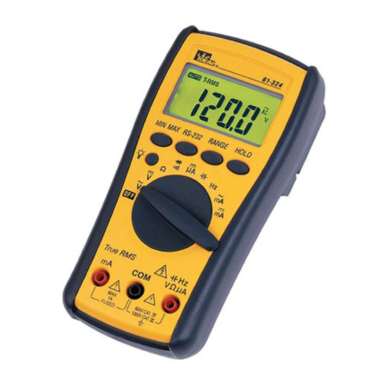
- Page 1 #61-322 #61-324 320 Series Contractor Grade Multimeter...
- Page 2 WARNING! 1. DO NOT UNDER ANY CIRCUMSTANCES EXCEED THESE RATINGS: • Voltage is not to exceed 1000 Volts. • Resistance, Capacitance, Logic and Continuity functions are not to be performed on circuits capable of delivering greater than 600 Volts. • Current measurements are not to be performed on circuits capable of delivering greater than 500 Volts 2.
- Page 3 1. MIN/MAX Switch • Pressing this button once results in the displayed maxi- mum value of the current reading. • Pressing the min/max button once more results in the displayed minimum value of the current reating. • If pressed a third time “Max Min” will flash on the LCD indicating that the minimum and maximum value are being recorded while the current reading is displayed.
- Page 4 2. RS-232 Button (61-324 only) • Pressing the RS-232 button activates data acquisition • When the RS-232 button is pressed RS232 will appear in the upper middle of the LCD display • Data will be sent to the computer through the optical RS-232 connection.
- Page 5 Overload Protection Function Overload Protection VAC & VDC 1000V AAC & ADC A input: 1A(600V) fast blow fuse µA input: 600V RMS Ohms ( ) 600VAC/600VDC Diode 600VAC/600VDC Continuity 600VAC/600VDC Unit of Measure Multipliers For your reference, the following symbols are often used to make measurement easier: Symbol Verbal...
- Page 6 True RMS AC Volt Circuit Connection: Range Resolution Accuracy Max. Display 600mV 100µV 600.0 ±(0.9% reading 6.000 10mV + 5 digits) 60.00 600V 100mV 600.0 1000V 1000 AC Conversion Type: AC conversions are AC-coupled, true RMS responding, calibrated to the RMS value sine wave input. Input and Impedance: 10M less than 100 pF.
- Page 7 DC Volts Circuit Connection: Range Resolution Accuracy Max. Display 600mV 100µV 600.0 ±(0.5% reading 6.000 10mV + 2 digits) 60.00 600V 100mV 600.0 1000V 1000 Input Impedance: 10M (over 1000M in 600mV range) To Measure DC Voltage: 1. Plug the black test lead into the COM port and the red test lead into the Hz V µA port.
-
Page 8: Range Resolution
True RMS AC Current Circuit Connection: Range Resolution Accuracy Voltage Burden 60mA 10µA +(1.5% 2V max 60.00 600mA 100µA reading +5 600.0 AC Conversion Type: AC conversions are AC-coupled, true RMS responding, calibrated to the RMS value sine wave input. Overload Protection: A input: 1A (600V) fast blow fuse Crest Factor: +1.5% additional error for C.F. - Page 9 DC Current Circuit Connection: Range Resolution Accuracy Voltage Burden 600µA 0.1µA < 4mV / µA 600.0 6000µA 1µA ±(1.0% reading 6.000 60mA 10µA + 2 digits) 2V max 60.00 600mA 100µA 600.0 Overload Protection: A Input: (600V) fast blow fuse µA Input: 600V RMS To Measure DC Current: 1.
-
Page 10: To Measure Frequency
Frequency/RPM Circuit Connection: Range Resolution Sensitivity Accuracy 6000Hz 60KHz 10Hz 100mV RMS Frequency: 600KHz 100Hz 0.01% ±1 digit 6MHz 1KHz 250mV RMS 60MHz 10KHz 1V RMS Overload Protection: 600V rms *Less than 20Hz the sensitivity is 1.5V To Measure Frequency: 1. - Page 11 Resistance (Ohms) Circuit Connection: Range Resolution Accuracy Max. Display 600.0 ±(0.7% reading 6.000 + 2 digits) 60.00 600K 600.0 6.000 60.00 Open Circuit Voltage: -1.3V approx. To Measure Resistance: 1. Turn the power off to the circuit or device that is to be measured and discharge all capacitors before attempting a measurement.
- Page 12 Multiplication Guide for Ohms ( ) 400 = Meter indicates actual resistance = Multiply meter display reading by 1,000 to acquire actual resistance. 40k = Multiply meter display reading by 1,000 to acquire actual resistance. 400k = Multiply meter display reading by 1,000 to acquire actual resistance.
- Page 13 Determining Resistor Values: To determine the value of a resistor, use the color bands on the resistor and the table on the following page. Resistor Color Code Table Tolerance Color Digit Digit Multiplier (Percentage) Black Brown Orange 1,000 Yellow 10,000 Green 100,000 Blue...
- Page 14 Diode Testing Function Resolution Accuracy Max.Test Max.Open Current Circuit Voltage +(1.5% +5)* 1.5mA * For 0.4V to 0.8V. Overload Protection: 600V rms max Diode Check: To ensure a proper functioning diode, the meter will develop a voltage across the component from a test current. The diode test function allows measurements of forward voltage drops across diode and transistor junctions.
- Page 15 Capacitance Circuit Connection: Range Resolution Accuracy 60nF 10pF 600nF 100pF ±(1.9% rading 6µF + 8 digits) 60µF 10nF 600µF 100nF 1µF Overload Protection: 600V rms To Measure Capacitance: 1. Plug the black test lead into the COM port and the red test lead into the Hz V µA port.
- Page 16 Continuity Check To Verify Continuity: A continuity test ensures that all circuit connections are intact. 1. Plug the black test lead into the COM port and the red test lead into the Hz V µA port. 2. Set the rotary switch to the position.
- Page 17 Accessories For AC Current Clamp (61-451): 1. Plug the black test lead of the clamp adapter handle into the COM port and the red test lead into the Hz V µA port. ˜ 2. Set the rotary switch to the V position. 3 Press the range button util mV is displayed.
- Page 18 General Specifications LCD Display: 6000 count maximum reading Polarity Indication: Automatic, negative indicated, positive implied Overrange Indication: “OL” or “-OL” Low Battery Indication: “ ” when the battery voltage drops below operating voltage Size (WxHxD): 82mm x 164mm x 44mm (without holster) Sampling: 1 time/sec LCD Display,...
-
Page 19: Maintenance
Maintenance Warning To avoid electrical shock, remove test lead before opening the cover. Repairs or servicing not covered in this manual should only be performed by qualified personnel. Battery Installation or Replacement: The #61-324 is powered by one 9V battery. 1. -
Page 20: Lifetime Limited Warranty
Any implied warranties arising out of the sale of an IDEAL product, including but not limited to implied warranties of merchantability and fitness for a particular purpose, are limited to the above.
Need help?
Do you have a question about the ND 3405-1 and is the answer not in the manual?
Questions and answers