Table of Contents
Advertisement
Quick Links
490 Series
Industrial Grade Multimeter
~Hz
PEAK
MIN/MAX
HOLD
Data Acquisition
#61-492
Data Acquisition
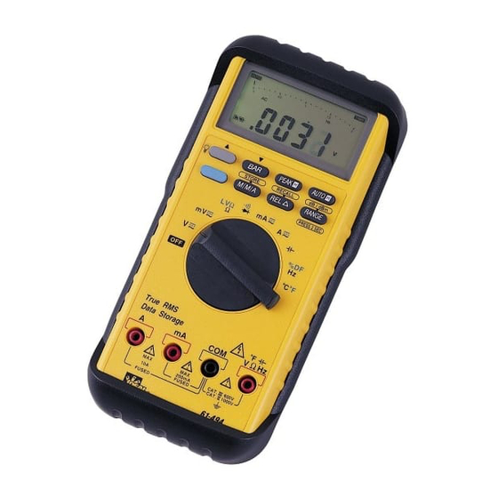
1. LCD Display
2. Rotary Function Switch
3. COM Input Terminal
4. V Hz Input Terminal
5. mA Input Terminal
6. A Input Terminal
7. Backlight Button
8. ~Hz Button
9. Peak H Button
10. Range Button
11. Blue Switch Button
12. Min/Max Button
13. REL Button
2
14. Hold Button
1
7
8
10
~Hz
PEAK
14
MIN/MAX
HOLD
13
11
2
3
4
5
6
2
2
9
12
Advertisement
Table of Contents

Subscribe to Our Youtube Channel
Related Manuals for IDEAL ND 2385-1


Summary of Contents for IDEAL ND 2385-1
- Page 1 #61-492 490 Series Industrial Grade Multimeter PEAK MIN/MAX HOLD Data Acquisition PEAK MIN/MAX HOLD 1. LCD Display 2. Rotary Function Switch 3. COM Input Terminal 4. V Hz Input Terminal 5. mA Input Terminal 6. A Input Terminal 7. Backlight Button Data Acquisition 8.
- Page 2 WARNING! Function Buttons 1. DO NOT UNDER ANY CIRCUMSTANCES EXCEED THESE The meter beeps once for every valid key-press, and beeps RATINGS: twice for every invalid key-press. - Voltage is not to exceed 1000 Volts. - Resistance, Capacitance, Logic and Continuity func- Backlight Button tions are not to be performed on circuits capable of deliv- •...
- Page 3 MIN MAX Button Auto Power Off Feature • The MIN/MAX button toggles between the stored mini- • If the meter is idle for more than 30 minutes, power is mum, and maximum values. automatically turned off. • Pressing the button the first time displays the minimum •...
- Page 4 AC Volts DC Volts Circuit Connection: Circuit Connection: PEAK PEAK HOLD MIN/MAX HOLD MIN/MAX Data Acquisition Data Acquisition Range Resolution Max Display Accuracy Range Resolution Max Display Accuracy 400mV 0.1mV 400.0 +(1.5% +8) 400mV 0.1mV 400.0 +(1.5% +8) 40Hz ~ 60Hz 400mV 100µV 400.0...
- Page 5 AC Current DC Current Circuit Connection: Circuit Connection: PEAK PEAK HOLD MIN/MAX MIN/MAX HOLD Data Acquisition Data Acquisition Range Resolution Max Display Accuracy Voltage Range Resolution Max Display Accuracy Voltage Burden Burden 40mA 1µA 40.00 +(1.0% +5) 300mV max 40mA 10µA 40.00 +(0.4% +2) 300mV max...
- Page 6 Frequency/RPM Resistance (Ohms) Circuit Connection: Circuit Connection: PEAK PEAK HOLD HOLD MIN/MAX MIN/MAX Data Acquisition Data Acquisition Range Resolution Max Display Accuracy Range Resolution Max Display Sensitivity Accuracy 400.0 ±(0.7% +3) 4kHz/40kRPM 1Hz/30RPM 4.000/40.00 150mV Frequency: 4.000 ±(0.4% +2) 2.0 Hz 0.01% +1 40.00 1.5V <...
- Page 7 Capacitance Diode Testing Circuit Connection: Circuit Connection: PEAK PEAK MIN/MAX HOLD HOLD MIN/MAX Data Acquisition Data Acquisition Range Resolution Max Display Accuracy Function Resolution Accuracy Max. Test Max. Open 4.000 +(3.0% +10) Current Circuit 40nF 10pF 40.00 +(3.0% +5) Voltage 400nF 100pF 400.0...
-
Page 8: Continuity Check
Continuity Check PEAK Hold Measurements Circuit Connection: PEAK PEAK HOLD MIN/MAX HOLD MIN/MAX Data Acquisition Data Acquisition To Verify Continuity: Function Range Accuracy Function Range Accuracy 1. A continuity test ensures that all circuit connections are 400mV unspecified 400mV unspecified intact. -
Page 9: Measurement Mode
The function packet indicates the measurement mode of Data Acquisition Function the meter. Status, option 1 and option 2 gives the status of 1. Auto Power Off (APO) the meter. CR and LF are delimiters used to separate the The APO sign on the LCD panel indicates the meter is blocks. - Page 10 - Range - Digit 3 - Digit 0 This packet indicates the full scale range of the meter. Digit 3 i the most significant digit on the LCD panel, and When the meter operates in continuity mode, diode mode digit 0 is the least significant digit. When the LCD panel or current (A) mode, this packet is always 0110000 since shows OL, the serial port outputs 4000.
-
Page 11: General Specifications
- Option 1 General Specifications This packet contains information on special measurement Display: The Liquid Crystal Display (LCD) modes. The format of this packet is shown below. The with a maximum reading of 4000 and three non-constant fields is set to one when the meter 82 segments bar graph. -
Page 12: Maintenance
This warranty does not apply to defects resulting from abuse, neglect, accident, unauthorized repair, alteration, or unreasonable use of the instrument. Any implied warranties arising out of the sale of an IDEAL product, Fuse Replacement including but not limited to implied warranties of merchantability 1.
Need help?
Do you have a question about the ND 2385-1 and is the answer not in the manual?
Questions and answers