Table of Contents
Advertisement
Quick Links
Advertisement
Table of Contents

Related Manuals for A&D AD-4408A


Summary of Contents for A&D AD-4408A
- Page 1 AD-4408A Weighing Indicator for Field Networks INSTRUCTION MANUAL 1WMPD4001973...
- Page 2 WARNING DEFINITIONS The warnings described in this manual have the following meanings: A potentially hazardous situation which, if not avoided, could result in death or serious injury. A potentially hazardous situation which, if not avoided, may result in minor or moderate injury or damage to the instrument . This symbol indicates caution against electrical shock.
-
Page 3: Table Of Contents
6.2. Mode Map ......................18 Calibration ........................19 7.1. General Description ..................19 7.2. Calibration With an Actual Load (Cal5et)............20 7.3. Calibration-Related Functions (Calf)..............22 7.4. Calibration Errors ....................28 7.5. Load Cell Output Adjustment ................29 General Functions ......................30 8.1. Setting Procedure .....................30 Page 1 AD-4408A... - Page 4 10.2.12. Checking the calibration-related functions ................40 10.3. Initialization Mode ...................41 10.3.1. RAM initialization / General functions initialization ..............41 10.3.2. All data initialization ........................ 42 11. Setting List........................43 11.1. Basic Functions....................43 11.2. Standard Serial Output..................44 11.3. Calibration-Related Functions .................45 12. External Dimensions....................47 Page 2 AD-4408A...
-
Page 5: Safety Precautions
Do not use the indicator in places where flammable gases are present. Indicator overheat To prevent the indicator from overheating, allow appropriate clearance between the peripheral devices. If the ambient temperature exceeds the specified operating temperature, use a fan to cool the environment. Page 3 AD-4408A... -
Page 6: Introduction
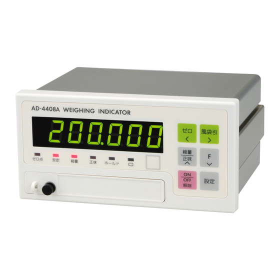
2. Introduction The AD-4408A is a weighing indicator that amplifies signals from a load cell, converts it to digital data and displays it as a weight value. Connection to various field networks is possible by installing the interface module into the option slot. -
Page 7: Specifications
• Overflow display All the digits turn OFF. (When the polarity is negative, the minus sign appears at the highest-order digit.) Status indicators ZERO, STABLE, GROSS, NET, HOLD, Key switches ZERO, TARE, NET/GROSS, F, ON/OFF, ENTER, CAL Page 5 AD-4408A... -
Page 8: General
0.0 to 9.9 seconds (Can be set optionally within the range.) • Stability detection band 0 to 9 d (Can be set optionally within the range.) Digital filter Cutoff frequency range (-3dB) : 0.7 to 11 Hz Page 6 AD-4408A... -
Page 9: Other
Operating humidity 85% R.H. or less (no condensation) Installation method Panel mount Mass Approximately 800 g 3.3.4. Accessories Item Quantity Model name Weighing capacity plate 108-4023454 Unit label 108-4023456 Panel mount packing 106-4004213 Terminal block cover 107-4005384 Page 7 AD-4408A... -
Page 10: Description Of Each Part
The function for this indicator can be selected in the general functions, depending on the purpose. • Place a unit label. UNIT • A unit used for weighing is set in the calibration-related functions. Page 8 AD-4408A... - Page 11 • The zero conditions are set in the calibration-related functions. ZERO • The key shifts the position of the blinking digit to the left when the numerical values are being entered. • Can be sealed using a wire seal. Seal Page 9 AD-4408A...
-
Page 12: Rear Panel
To avoid unintentional operations, keep the cover attached on the terminal block. 2 Blank panel Option slot inside to install the interface module. 3 Testing terminal Do not use, leave this terminal unconnected. 4 Sealing bolts Can be sealed with a wire seal. Page 10 AD-4408A... -
Page 13: Installation
It makes the front panel water-resistant equivalent to IP-65. Panel mount packing Guide rail Control panel Washer Screw Fig.3 Panel mounting method Page 11 AD-4408A... -
Page 14: Power Source
The output voltage of a load cell is a very sensitive signal. Keep all electrical noise sources away from the load cell and load cell cable. Use shielded I/O cables. Connect the cable shield to the F.G. terminal or the indicator housing. Page 12 AD-4408A... -
Page 15: Load Cell Connection
SEN+) and terminals 3 and 4 (SEN- and EXC-) connected may be used, but the error increases when summing multiple load cells and the cable is long. Load cell Load cell cable EXC+ SIG+ SIG- EXC- Shield Fig.4 Load cell connection Page 13 AD-4408A... -
Page 16: Interface Module Installation
5.3. Interface Module Installation Be sure to disconnect the AD-4408A from the power source before installing the interface module. Install the interface module as follows: Blank panel Step 1 Using a Phillips screwdriver, Step 1 loosen the screws that secure... -
Page 17: Operation
A ZERO error is not output even if zero tracking is not performed. Functions related to zero tracking Calf06 : Changes the zero tracking time. (0.0 to 5.0 seconds) Calf07 : Changes the zero tracking band. (0.0 to 9.9 d) Page 15 AD-4408A... -
Page 18: Tare
Press the switch once and release the switch to turn ON or OFF. Press the switch again to turn OFF or ON. Momentary switch Only when the switch is being pressed, the F key is ON. When released, OFF. Page 16 AD-4408A... -
Page 19: Display
ON when the F key is ON and turns OFF when the F key is OFF. 6.1.6. Memory backup Zero value, tare weight, calibration data and function data are written into the FRAM. FRAM is a non-volatile memory and does not require batteries. Data retention time is 10 years. Page 17 AD-4408A... -
Page 20: Mode Map
NOTE: When the power is Calibration Calibration-related disconnected while in mode function mode the OFF mode, the Enter using the CAL key indicator will start in All data the OFF mode when initialization mode power is re-connected. Fig.6 Mode map Page 18 AD-4408A... -
Page 21: Calibration
(The input voltage at span is related to the weight value.) Clears all the data such as zero value, tare weight, All data initialization calibration data and function data. NOTE: All the data set in the calibration mode is stored in the FRAM. Page 19 AD-4408A... -
Page 22: Calibration With An Actual Load (Cal5Et)
Step 6 Place a calibration weight on the load cell. Wait for the stabilization indicator to turn ON and press the ENTER key. - - - - - - is displayed for approximately two seconds. Page 20 AD-4408A... - Page 23 ESC key again. NOTE: The blinking decimal point indicates that the current value is not the weight value. If C errX is displayed, an error has occurred. Refer to “7.4. Calibration Errors” to take some measures. Page 21 AD-4408A...
-
Page 24: Calibration-Related Functions (Calf)
Press the ESC key again to go back to the weighing mode. NOTE: The blinking decimal point indicates that the current value is not the weight value. If a value exceeding the settable range is entered, err dt is displayed and the input is canceled. Page 22 AD-4408A... - Page 25 Calf05 adjustment the center. range For example, if this is set to 2, the value in the range of ±2% of the weighing capacity with the calibration zero point at the center will set to zero. Page 23 AD-4408A...
- Page 26 Zero tracking functions when the weight value 3.0 d is drifting within the range shown in the 2.0 d graph. 0.5 d 1.0 d When CALF06 = 2.0 CALF07 = 1.0 0 second 1 second 2 seconds Page 24 AD-4408A...
- Page 27 Tare when the gross weight is negative. Calf11 gross 0: Disables tare. weight 1: Enables tare. negative Output Standard serial output when the weight value when Calf12 overflows and is unstable. overflow 0: Disables output. 1: Enables output. unstable Page 25 AD-4408A...
- Page 28 Input voltage at span of weight value Calf19 Calf17 corresponding When performing digital span, 20000 999999 to Input are required. voltage at The decimal point position is the same as span Calf02 the setting of Page 26 AD-4408A...
- Page 29 Communication auto printing restriction 0: Disables restriction. 1: Enables restriction. NOTE: To receive a Measuring instruments directive (MID) approval, network- related communication must be restricted. Confirm that “ : Enables Calf21 restriction” is selected for (Communication restriction). Page 27 AD-4408A...
-
Page 30: Calibration Errors
C err8 when the load of the weighing capacity greater rating or make the is placed. weighing capacity smaller. Voltage at span calibration is less than Check load cell C err7 voltage at the zero point. connection. Page 28 AD-4408A... -
Page 31: Load Cell Output Adjustment
Use a resistor with a high resistance value and a low temperature coefficient. "C Err 2" "C Err 3" (When exceeding in the positive direction) When exceeding in the negative direction) EXC+ EXC+ SIG+ SIG+ SIG- SIG- EXC- EXC- Fig.7 Load cell output adjustment Page 29 AD-4408A... -
Page 32: General Functions
8. General Functions General functions are divided into groups per function and are indicated by the group name with the function number. NOTE: General functions determine the AD-4408A performance and all of the settings are stored in the FRAM. 8.1. Setting Procedure Step 1 While pressing and holding the ENTER key, press the F key. - Page 33 Press the ESC key to store the setting values in the FRAM and go back to the weighing mode. NOTE: The blinking decimal point indicates that the current value is not the weight value. If a value exceeding the settable range is entered, err dt is displayed and the input is canceled. Page 31 AD-4408A...
-
Page 34: Basic Functions (Fncf)
4: 4.0 Hz filter 5: 2.8 Hz 6: 2.0 Hz 7: 1.4 Hz 8: 1.0 Hz 9: 0.7 Hz Frequency fncf06 Divides digital filter cutoff frequency by the divider setting. ratio fncf07 1: Normal hold Hold 2: Peak hold Page 32 AD-4408A... -
Page 35: Standard Serial Output (Cl F)
ID number ⏐ Calf21 NOTE: When “ : Enables restriction” is selected for (Communication restriction): (Note 1) Auto printing will not be performed even if auto printing conditions are met. (Note 2) ID numbers can not be changed. Page 33 AD-4408A... -
Page 36: Interface
No polarity C.L. F.G. Fig.8 Standard serial output pin connection Fig.9 Standard serial output internal circuit NOTE: The standard serial output connection has no polarity. When a shielded cable is used, connect the shield to the F.G. terminal. Page 34 AD-4408A... -
Page 37: Output Data
5 k g Same as “Output OFF” data C R L F O L , G S , + SP SP SP SP SP SP positive overflow NOTE: The decimal point position is the same even when overflow occurs. Page 35 AD-4408A... -
Page 38: Data Transfer Mode
The example below is when an ID number is added. C R L F S T , G S , + 0 1 2 3 . 4 5 k g ID number Calf20 : Enables or disables the print command when the gross weight is negative. Page 36 AD-4408A... -
Page 39: Maintenance
Step 3 Press the ∧ or ∨ key to select the item to be checked and press the ENTER key to enter the check mode of the selected item. To exit from the current mode, press the ESC key. Page 37 AD-4408A... -
Page 40: Checking The Key Switches
0 . 0 C R L F Test data S T , G S , + 0 0 0 0 0 . 0 k g Page 38 AD-4408A... -
Page 41: Checking Interfaces
The example below is when the last five digits of the serial number are 12345. 1 2 3 4 5 . 10.2.10. Checking the program checksum With C5 pr9 displayed, press the ENTER key to display the program checksum. The example below is when the checksum is EF. Page 39 AD-4408A... -
Page 42: Checking The Fram Checksum
10.2.12. Checking the calibration-related functions With CalfdtP displayed, press the ENTER key to display the settings of the calibration-related functions. NOTE: For contents and operations of the calibration-related functions, refer to “7.3. Calibration-Related Functions”. The settings can not be changed here. Page 40 AD-4408A... -
Page 43: Initialization Mode
ENTER key for three seconds or more. After initialization, the indicator is reset and all the display segments are ON. And the indicator enters the weighing mode. To exit from this mode without performing initialization, press the ESC key. Page 41 AD-4408A... -
Page 44: All Data Initialization
ENTER key for three seconds or more. After initialization, the indicator is reset and all the display segments are ON. And the indicator enters the weighing mode. To exit from this mode without performing initialization, press the ESC key. Page 42 AD-4408A... -
Page 45: Setting List
2: 8.0 Hz 3: 5.6 Hz fncf05 4: 4.0 Hz 5: 2.8 Hz 6: 2.0 Hz 7: 1.4 Hz 8: 1.0 Hz 9: 0.7 Hz fncf06 Frequency divider ratio Hold fncf07 1: Normal hold 2: Peak hold Page 43 AD-4408A... -
Page 46: Standard Serial Output
5: Gross/Net/Tare Data transfer mode Cl f02 1: Stream 2: Auto printing 3: Manual printing Baud rate Cl f03 1: 600 bps 2: 2400 bps ID number 0: Does not add an ID number. Cl f04 ⏐ Page 44 AD-4408A... -
Page 47: Calibration-Related Functions
0: Disables both functions. 1: Enables both functions. Tare when the gross weight is negative. Calf11 0: Disables tare. 1: Enables tare. Standard serial output if the weight value Calf12 overflows and is unstable. 0: Disables output. 1: Enables output. Page 45 AD-4408A... - Page 48 999999 Select whether or not to output when the Calf20 gross weight is negative. 0: Enables output. 1: Disables output. Select whether or not to restrict Calf21 network-related communication. 0: Disables restriction. 1: Enables restriction. Page 46 AD-4408A...
-
Page 49: External Dimensions
12. External Dimensions (134.7) Net/B/G 16 (3.2) 99.5 Panel cutout dimensions Unit: mm Fig.10 External dimensions Page 47 AD-4408A... - Page 50 MEMO Page 48 AD-4408A...
Need help?
Do you have a question about the AD-4408A and is the answer not in the manual?
Questions and answers