Table of Contents
Advertisement
Advertisement
Table of Contents

Related Manuals for A&D AD-4961-2KD-2035


Summary of Contents for A&D AD-4961-2KD-2035
- Page 1 AD-4961-2KD-2035 CHECKWEIGHER INSTRUCTION MANUAL 1WMPD4002855...
- Page 2 WARNING DEFINITIONS The warnings described in this manual have the following meanings: A potentially hazardous situation which, if not avoided, could result in death or serious injury. A potentially hazardous situation which, if not avoided, may result in minor or moderate injury or damage to the instrument . This symbol indicates caution against electrical shock.
-
Page 3: Table Of Contents
Contents Introduction ..............................6 1.1. Features .............................. 6 1.2. Safety Precautions ..........................7 Description of Individual Parts ........................8 2.1. Whole View ............................8 2.2. Display..............................9 2.2.1. Description of individual parts ...................... 9 2.2.2. Connecting the USB memory ....................10 2.3. - Page 4 4.6.6. Setting the delay and hold time....................34 4.6.7. Changing the product to be weighed ..................36 4.6.8. Measuring the product length ....................37 4.6.9. Registering the product image....................39 4.6.10. Copying the product settings ..................... 40 4.6.11. Deleting the product settings ..................... 41 4.7.
- Page 5 Detailed Description of the Setting Values....................69 8.1. Product Name/Product Code ......................71 8.1.1. Product name..........................71 8.1.2. Product code..........................71 8.2. Judgment Basis..........................71 8.2.1. Target value ..........................71 8.2.2. High limit value........................... 71 8.2.3. Lower limit value ........................71 8.2.4.
- Page 6 8.8.3. Minimum division ........................75 8.8.4. Unit............................. 75 8.9. Stability Detect........................... 76 8.9.1. Stable mass range ........................76 8.9.2. Stable time range ........................76 8.10. Zero Revision ............................ 76 8.10.1. Zero adjustment range....................... 76 8.10.2. Zero tracking mass range ......................76 8.10.3.
- Page 7 8.15.3. Chattering........................... 83 8.15.4. Polarity ............................83 8.16. External Devices ..........................83 8.16.1. Monitoring the rejector ....................... 83 8.16.2. With metal detector ........................83 8.16.3. Printer IP address ........................83 8.16.4. Printer connection method ......................83 8.17. Date/Time............................83 8.17.1. Date............................83 8.17.2.
-
Page 8: Introduction
1. Introduction 1.1. Features The AD-4961 is a checkweigher developed for checkweighing products. Display ・ Excellent and easy operability with 7-inch touch sensitive panel Dustproof・waterproof construction ・ Waterproof construction complying with IP65 Conveyor construction ・ The gear-driven conveyor mechanism allows easy removal of conveyor and maintenance. Functions ・... -
Page 9: Safety Precautions
1.2. Safety Precautions To use the AD-4961 checkweigher safely, read the following precautions before use. Hazard of rotating object ・ Keep hands and fingers away from the rotating part while the checkweigher is running. ・ If the product accumulates, falls over or spills on the checkweigher, stop the checkweigher immediately, turn the power off and take necessary actions. -
Page 10: Description Of Individual Parts
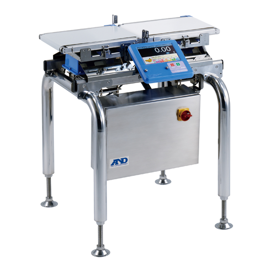
2. Description of Individual Parts 2.1. Whole View 2. Photosensor/ 8. Rejector conveyor Reflector (Option) 1. Infeed conveyor 3. Weighing conveyor 7. Flipper type rejector 4. Display 5. Control box 6. Power switch (Option) Fig.1 Whole view Name Description Infeed conveyor Conveys the product to the weighing conveyor. -
Page 11: Display
2.2. Display 2.2.1. Description of individual parts 1. Operation panel 2. STOP button 3. START button 4. USB terminal cover Fig.2 Display Name Description Operation panel Displays the Weighing screen and other screens. Used to change the settings and operate the checkweigher. STOP button Finishes the weighing operation and stops the conveyor. -
Page 12: Connecting The Usb Memory
2.2.2. Connecting the USB memory With the AD-4961 checkweigher, the USB memory can be used to register the product images and save the weighing data. Remove the USB terminal cover on the display by turning the screws. Insert the USB memory into the USB terminal When the USB memory is recognized, the USB mark appears on the upper right side of the screen. -
Page 13: Control Box
2.3. Control Box 1. General purpose 2. General purpose output terminal 3. LAN connector input terminal 4. Serial interface Fig.4 Control box Name Description General purpose output terminal Outputs the weighing results. General purpose input terminal Inputs data from external devices. LAN connector Used to connect a printer or for Modbus communication. -
Page 14: Operating The Screens
3. Operating the Screens This chapter describes basic operations of the screens that appear on the operation panel. 3.1. Icons This section describes the functions of the icons commonly used in various screens. Other icons are described as they appear. Icon Name Description... -
Page 15: Pulldown Selection
3.3. Pulldown Selection When an item selection is required, the pulldown selection dialog box appears. Item to be selected Scroll bar Fig. 6 Pulldown selection dialog box 1. Select an item and touch the OK button. The selected item is confirmed. 3.4. -
Page 16: Entering The Characters
3.5. Entering the Characters When a character is required, the character entry dialog box appears. Input keys Fig.8 Character entry dialog box MODE key Name Description MODE key Switches the characters to be input. Input BS key Deletes a character before the cursor. keys CLR key Deletes all the characters entered. -
Page 17: Entering The Password
3.6. Entering the Password When a password is required for a user login or user registration, the Password entry dialog box appears. Password input field Input keys Fig.9 Password entry dialog box Name Description Password input field The entered password will be indicated by (asterisks). -
Page 18: Basic Operations
4. Basic Operations This chapter describes the basic operations of the checkweigher. 4.1. Operation Outline This section outlines the operations. The work flowchart below shows the daily operation. For details on each operation, refer to the relevant section. Starting up the checkweigher Refer to “4.2. -
Page 19: Turning The Power On
4.2. Turning the Power ON 1. Turn the power switch 90 degrees clockwise to the ON (I) position. Fig.10 Power switch 2. After the checkweigher startup, the Weighing screen appears. Fig.11 Weighing screen (Initial screen) -
Page 20: Turning The Power Off
4.3. Turning the Power OFF Turn the power switch 90 degrees counterclockwise to turn off and stop the checkweigher. Note: For emergency stop, perform the above operation. In that case, before turning the power ON again, be sure to resolve the cause of the stop. Fig.12 Power switch... -
Page 21: Weighing Operation
4.4. Weighing Operation This section describes the weighing operation. Note: This section is described under the assumption that the product has been registered and set beforehand. For details about the product registration and setting, refer to “4.6. Selecting the Product / Changing the Detect Function Settings.”... -
Page 22: Adjusting Zero
Simple summary Belt speed Processing number Fig.14 Display example (Reduced regular display) The regular display displays the product weighing value as is, or the value with the tare value subtracted when the tare value is set. The deviation display displays the difference between the product weighing value and the target value. In the deviation display, the deviation mark appears in the weighing value field of the Weighing screen. -
Page 23: Starting / Stopping The Weighing Operation
• An excessive load is applied to the conveyor and the load cell is deformed. • An upward excessive load is applied to the load cell, for example, raising the checkweigher by holding the conveyor, and the load cell is deformed. If the weighing value is not zero even after the foreign substances are removed and zero adjustment is performed, calibration using a weight is required. -
Page 24: Management Level And User Edition/Login
4.5. Management Level and User Edition/Login With the checkweigher, users can be registered and the management level is assigned to each user to limit available operations. This section describes the management level, user edition and login procedure. Note: ・ The checkweigher has default user information registered before shipment as follows: User name: Admin, Password: 0000 (four zeros), Management level: Administrator ・... -
Page 25: Changing The User
4.5.2. Changing the user The management level that appears when the power is turned on is Operator. To change the user, user login authentication is required. The user login authentication procedure is as follows: Note: The checkweigher has default user information registered as follows: User name: Admin, Password: 0000 (four zeros), Management level: Administrator In the Weighing screen, touch the User key to open the User Login screen. -
Page 26: Registering The User
4.5.3. Registering the user The user registration procedure is as follows: In the User Login screen, touch the Edit key to open the User Edition screen. Contents to edit Users list Fig.16 User Edition screen Select the Register User Name field and enter the user name to be registered. Select the Register Password field and enter the four-digit password. -
Page 27: Changing The User Information
4.5.4. Changing the user information In the User Information Change screen, the contents of the user information registered can be changed. The user information changing procedure is as follows: In the User Login screen, touch the Edit key to open the User Edition screen. Touch the Change key to open the User Selection screen. -
Page 28: Deleting The User
Select the New Password field and enter the new four-digit password. Select the Management level field and select an appropriate level for the user from Administrator, Quality Manager or Supervisor. Touch the Change button to confirm the new user settings. 4.5.5. - Page 29 Deleting a selected user Select a user to be deleted from the Users List. Touch the Delete button to open the user deletion confirmation dialog box. Touch the Yes button to delete the selected user. Fig.20 User deletion confirmation dialog box (A selected user) The selected user will be deleted from the Users List.
-
Page 30: Selecting The Product / Changing The Detect Function Settings
4.6. Selecting the Product / Changing the Detect Function Settings This section describes the product selection and detect function settings changing procedures. The product registration is available only for the management level of Quality Manager or above. This section is described under the assumption that the checkweigher has been logged in by the user with the management level of Quality Manager. - Page 31 Touch the Edit key to register the product and open the Product Setting screen. In the Product Setting screen, the product name or code is entered, the product image is registered and the settings are copied or deleted. Note: ・ Touching the Image button will open the Image Selection screen to register images saved in the USB memory. For details, refer to “4.6.9.
-
Page 32: Setting The Target, High Limit And Lower Limit Values
4.6.2. Setting the target, high limit and lower limit values The values used for detection are set. Touch the Detect Basis button of the setting menu to open the screen below. Fig.25 Detect Basis Setting screen Select Target to enter the mass of the product to be weighed. Select High Limit to enter the upper limit mass value of the product. -
Page 33: Setting The Product Length, Processing Number And Belt Speed
4.6.3. Setting the product length, processing number and belt speed The values related to the processing performance are set. Touch the Processing Performance button of the setting menu to open the screen below. Fig.26 Processing Performance Setting screen Select Product Length to enter the length of the product. Touching the Measure a Product Length button will measure the length of the product automatically. -
Page 34: Setting The Tare Value
4.6.4. Setting the tare value The tare value is set. Touch the Revision button of the setting menu to open the screen below. Fig.27 Revision Setting screen Place a tare on the weighing conveyor and touch the Get button. The tare mass on the weighing conveyor will be set as the tare value. When the tare value is known, the value can be entered directly in the Tare Value field. -
Page 35: Setting The Digital Output (Do)
4.6.5. Setting the digital output (DO) DO related items and whether or not to stop the conveyor according to the judgment result are set. Touch the DO Map button of the setting menu to open the screen below. Judgment items Stopping the conveyor DO number Check box... -
Page 36: Setting The Delay And Hold Time
When the product is weighed and the judgment item is judged, a signal will be output from the specified DO according to the delay time and hold time. For details about the delay and hold time, refer to “4.6.6. Setting the delay and hold time.” When the Stop column is checked, the conveyor will stop according to the result of the specified judgment item. - Page 37 Touch the DO Behavior button of the setting menu to open the screen below. Touch the Left arrow key or Right arrow key to switch the judgment items. Fig.31 DO Behavior Setting screen Select Delay Time to enter a delay time for each DO. e.g.: connecting DO1 to the flipper type rejector A basic delay time is the time a product moves from the weighing conveyor to the rejector.
-
Page 38: Changing The Product To Be Weighed
4.6.7. Changing the product to be weighed The product changing procedure is as follows: In the Weighing screen, touch the Product key to open the Product Selection screen. Enter the group No. (1 to 10). Touch the Left arrow key or Right arrow key to switch the Registration pages. Touch the product No. -
Page 39: Measuring The Product Length
4.6.8. Measuring the product length A product is fed on the conveyor and the photosensor measures the length of the product. Repeat the procedure three times and the average of the three measurements is set as the product length. The product length measurement procedure is as follows: Note: The length of a transparent product may not be measured. - Page 40 When the measurement is complete, the screen below appears. Touch the Apply Length button to set the average product length as the product length. Fig.36 Product length measurement completion screen The Product length measurement start screen appears. Touch the RETURN key to return to the Processing Performance Setting screen.
-
Page 41: Registering The Product Image
4.6.9. Registering the product image The product image registration procedure is as follows: Note: ・ Images must be saved in USB memory beforehand. ・ Image file names with spaces cannot be registered. ・ Images that can be registered are JPEG files. ・... -
Page 42: Copying The Product Settings
Touch the OK key to register the selected product image. The registered product image will appear in the Product Setting screen (Edit tab). Registered product image Fig.39 Registered product image example 4.6.10. Copying the product settings The settings of the registered product can be copied to another product number. The product setting copying procedure is as follows: Open the Product Setting screen (Edit tab). -
Page 43: Deleting The Product Settings
4.6.11. Deleting the product settings The registered product settings can be deleted. The product setting deletion procedure is as follows: Open the Product Setting screen (Edit tab). Touch the Delete button to open the dialog below. Touch the Yes button to delete the registered product settings. Fig.41 Setting deletion confirmation dialog box 4.... -
Page 44: Summary Of Weighing Results
4.7. Summary of Weighing Results This section describes the weighing result summary. Note: ・ Histograms, control charts and summary results can be output to the USB memory or printer. For details, refer to “6. Output.” ・ Only USB memory formatted in FAT32 can be used. For details about the USB memory formatting procedure, refer to “7.1. -
Page 45: Histogram
4.7.2. Histogram A histogram displays the frequency distribution of the total weighing results (all summary) (including the failed products) of the selected product number. To display or print a histogram, the target value and class width must be set beforehand. Frequency Border value Fig.43 Histogram screen... -
Page 46: Control Chart
Relation between the border value and the class width Target value: S, Class width: k Class No Border value Class width w<W ‐ =S-7k ≦w<W =S-6k ≦w<W =S-5k ≦w<W =S-4k ≦w<W =S-3k ≦w<W =S-2k ≦w<W =S-k ≦w<W ≦w<W =S+k ≦w<W =S+2k ≦w<W =S+3k... - Page 47 e.g.: When the number of samples is 10 and the sample size (sub samples) is 5: Out of 10 data that is set as the number of samples, the first five is used to make a control chart. 1 2 3 4 5 6 7 8 9 10 1 2 3 4 5 6 7 8 9 10 1 2 3 4 5 6 7 8 9 10 ○:Not for control chart Number of samples Control chart data (Sub samples)
-
Page 48: R Control Chart
4.7.4. control chart control chart is displayed based on the number of samples, sample size (sub samples) and the setting value of When is set, a graph is displayed according to When is set to 0, is calculated using the weighing data acquired for a control chart to display a graph. Note: For details on setting, refer to “8.7.4. -
Page 49: All Summary
4.7.5. All summary All summary is the summary of total weighing results including the failed products. Summary data of all the weighed products Statistical data of all the weighed products such as average Fig.46 All Summary screen Touch the Clear key to clear all summary data. -
Page 50: Ok Summary
4.7.6. OK summary OK summary is the summary of the weighing results of the passed products (OK) of the currently selected product number. Fig.47 OK Summary screen Touch the Right arrow key to go to the Number of Samples Summary screen. Touch the RETURN key to return to the Weighing screen. -
Page 51: Number Of Samples Summary
4.7.7. Number of samples summary Number of samples summary is the summary of the weighing results per the specified sample number of the currently selected product. This summary includes the failed products. When weighing the specified sample number is complete, the summary process will be reset. e.g.: When the number of samples is 10: 1 2 3 4 5 6 7 8 9 10 1 2 3 4 5 6 7 8 9 10 1 2 3 4 5 6 7 8 9 10... -
Page 52: Number Of Ok Samples Summary
4.7.8. Number of OK samples summary Number of OK samples summary is the summary of the passed products as many as the specified sample number. When weighing the passed products as many as the specified sample number is complete, the summary process will be reset. -
Page 53: Adjustment Operations
5. Adjustment Operations This chapter describes operations related to adjusting the AD-4961-2KD-2035 checkweigher. 5.1. Calibrating the Checkweigher Using a Weight The checkweigher calibration procedure is as follows: Log in by the management level of Quality Manager or above. In the Weighing screen, touch the Setting key to open the Common Setting screen. - Page 54 Place nothing on the weighing conveyor and touch the Adjust zero button to set the zero point. When the zero point is known, the zero point value can be entered directly in the Zero point field. Enter the mass of the calibration weight in the Weight field. Place the calibration weight on the weighing conveyor and touch the Adjust span button to set the span value.
-
Page 55: Adjusting The Belt Speed
5.2. Adjusting the Belt Speed Belt speed adjustment is required when the actual belt speed is different from the speed that is set in the Processing Performance Setting screen. (Refer to “4.6.3. Setting the product length, processing number and belt speed.) Belt speed adjustment adjusts the speed of the infeed conveyor, weighing conveyor and rejector conveyor. - Page 56 Touch the Belt Speed Adjustment button to open the Belt Speed Adjustment dialog box. Touch the OK button to open the Belt Speed Adjustment screen. Fig.54 Belt Speed Adjustment dialog box Touch the Left arrow key or Right arrow key to select the conveyor. Belt speed field Setting Conveyor...
- Page 57 Enter the measured speed in the Low Speed field of the selected conveyor. For example, when the low speed and infeed conveyor are selected and the measured speed is 40m/min, enter 40 in the field shown below. Fig.56 Belt speed adjustment example Touch the Belt Speed to select High Speed.
-
Page 58: Setting The Date/Time
5.3. Setting the Date/Time The date and time of the checkweigher can be corrected. The date/time setting procedure is as follows: Log in by the management level of Quality Manager or above. In the Weighing screen, touch the Setting key to open the Common Setting screen. -
Page 59: Setting Lan
5.4. Setting LAN The LAN setting procedure is as follows: Log in by the management level of Quality Manager or above. In the Weighing screen, touch the Setting key to open the Common Setting screen. Select the System 1 tab and touch the LAN button to open the LAN Setting screen. Fig.59 LAN Setting screen Set the IP address, subnet mask and default gateway. -
Page 60: Output
6. Output The checkweigher can output the data to the USB memory or printer. 6.1. Outputting to the USB memory Data that can be output to the USB memory are weighing history, histogram, control chart and summary results. Note: ・ Only USB memory formatted in FAT32 can be used. ・... -
Page 61: Weighing History Output Example
6.1.2. Weighing history output example The format of the weighing history that is output to the USB memory is as follows “Date, time (hour : minute : second, 10 millisecond), product No., weighing result, judgment” The output example is shown below. Weighing Date 10 millisecond... -
Page 62: Outputting The Histogram, Control Chart, Summary Results Pdf Files
6.1.3. Outputting the histogram, control chart, summary results PDF files The histogram, control chart and summary results can be output to the USB memory as PDF files. The PDF file outputting procedure is as follows: Note: For contents of histogram, control chart and summary results that are output to the USB memory, refer to “6.2.2.” to “6.2.4.”... -
Page 63: Outputting To The Printer
6.2. Outputting to the Printer The histogram, control chart and summary results can be output to the printer. Note: ・ For a printer output, a PostScript printer is required. ・ This chapter is described under the assumption that a printer has been connected. For details about a printer connection, refer to “7.3. -
Page 64: Histogram Printing Example
6.2.2. Histogram printing example A histogram printing example is shown below. A PDF file that is output to the USB memory looks the same. Printed date and time Settings Product No., Product name, Product code, Target value, High limit value, Lower limit value, Center value of the histogram, Reject Over, Tare value, Processing number, Belt speed... -
Page 65: Control Chart Printing Example
6.2.3. Control chart printing example A control chart printing example is shown below. A PDF file that is output to the USB memory looks the same. Printed date and time Settings Product No., Product name, Product code, Target value, High limit value, Lower limit value, Number of samples, Sample size (Sub samples) control chart... -
Page 66: Summary Results Printing Example
6.2.4. Summary results printing example A summary results printing example is shown below. A PDF file that is output to the USB memory looks the same. Printed date and time Settings Product No., Product name, Product code, Target value, High limit value, Lower limit value, Reject Over, Tare value, Processing number, Belt speed Summary data... -
Page 67: External Devices
7. External Devices 7.1. Formatting the USB Memory This section describes the USB memory formatting procedure. Caution: Formatting the USB memory will delete all the data saved in the memory. The deleted data will not be restored. Before formatting, save necessary data into other media such as a personal computer. - Page 68 The USB Memory screen opens. Fig.66 USB Memory screen Touch the USB Format button. The confirmation dialog box opens. Touch the OK button to format the USB memory. When formatting is complete, touch the RETURN key to return to the Common Setting screen.
-
Page 69: Connecting A Lan
7.2. Connecting a LAN The LAN connection is used when Modbus communication is performed using Modbus/TCP. Insert one end of a commercially available LAN cable into the LAN connector located on the control box. And insert the other end of the cable into the LAN connector on a Modbus master device or into the Ethernet hub connected to a Modbus master device. -
Page 70: Connecting To The Serial Interface
7.4. Connecting to the Serial Interface The serial interface on the checkweigher is compatible with RS-232 and RS-485 standards. RS-232 and RS-485 are on the same screw terminal. Select one to use. For the connector position, refer to “2.3. Control Box.” The enlarged view of the interface is shown below. -
Page 71: Detailed Description Of The Setting Values
8. Detailed Description of the Setting Values Setting values in the Product Setting screen and Common Setting screens are shown below. List of product settings Product name Edit tab Product code Target value High limit value Detect Basis Lower limit value (Judgment Reject Over basis) - Page 72 List of common settings Stable mass range Stability Detect Stable time range Zero tracking mass range Zero Revision Balance tab Zero tracking time range Calibration weight value Zero point Span Weighing conveyor length Curb chattering Main Unit Rotation direction Conveyor mode Language Mass display mode Negative mass value...
-
Page 73: Product Name/Product Code
8.1. Product Name/Product Code 8.1.1. Product name Enter the name with a maximum of 12 characters to display in the Weighing and Product Setting screens. 8.1.2. Product code Enter the product code name with a maximum of 20 characters to display in the Weighing and Product Setting screens. -
Page 74: Processing Number
8.2.8. Processing number Enter the number of products to weigh in one minute. When the number is entered, the belt speed will be calculated automatically using the value and the weighing conveyor length. 8.2.9. Speed Enter the belt speed of the conveyor. When the speed is entered, the processing number will be calculated automatically using the speed and the weighing conveyor length. -
Page 75: Do Behavior
8.4. DO Behavior 8.4.1. Delay time Enter the time elapsed from judgment result output until a signal is output from the specified DO. For details, refer to “4.6.6. Setting the delay and hold time.” 8.4.2. Hold time Enter the time a signal is being output from the specified DO. For details, refer to “4.6.6. -
Page 76: Auto Zero
8.6.2. Auto zero Performs zero adjustment automatically when “Enable” is selected for “Auto Zero”. When conditions of auto zero range, dead zone timer and monitoring timer are met while the conveyor is moving, the mass values obtained during the averaging time are averaged. Using the average value as zero, zero adjustment is performed automatically. -
Page 77: Statistical
8.7. Statistical 8.7.1. Number of samples Enter the number of samples to be used for generating control charts and summary results. 8.7.2. Sample size (Sub samples) Enter the number of samples to be used to obtain the average for the control chart. 8.7.3. -
Page 78: Stability Detect
8.9. Stability Detect 8.9.1. Stable mass range Enter the mass range to detect stability. 8.9.2. Stable time range Enter the time range to detect stability. 8.10. Zero Revision 8.10.1. Zero adjustment range Enter the range to adjust zero. When the actual mass value is not within the range, zero adjustment or zero tracking will not be performed. 8.10.2. -
Page 79: Span
8.11.3. Span Enter the span value at 2 kg in mV/V. 8.12. Main Unit 8.12.1. Weighing conveyor length Enter the weighing conveyor length. Do not attempt to change the value. Only the A&D service personnel is allowed to do it. 8.12.2. -
Page 80: Display
8.13. Display 8.13.1. Language Set the displaying language, Japanese or English. 8.13.2. Mass display mode Set how to display the mass value when weighing. Each mode is as follows: 1. Holding the weighing result When a product passes through the photosensor and weighing is started, the displayed mass value changes. When the weighing is complete, the displayed mass value is fixed to the weighing result. -
Page 81: Connection
8.14. Connection 8.14.1. Serial mode Set the serial communication mode. Note: To perform serial communication, the checkweigher must be connected to the serial interface. For details, refer to “7.4. Connecting to the Serial Interface.” Each mode is as follows: 1. Disable Select to disable the serial communication. -
Page 82: Output Mode
8.14.2. Output mode Set the output mode when “A&D format” is selected for “Serial mode.” Each mode is as follows: 1. Current value Outputs the current mass value. 2. Weighing results Outputs the weighing results when the judgment is complete. 3. -
Page 83: Digital Input (Di)
8.15. Digital Input (DI) DI is accepted when the pulse is entered for the duration of “curb chattering”+20 msec or more in the DI receive time shown in the timing chart below. Judgment is performed when the product is beginning to clear of the weighing conveyor. Detected DI Detected Judgment 検出... - Page 84 Setting items are as follows: (1) Disable Select to disable the function. The Modbus setting is 0. (2) Weighing start Select to assign the start weighing signal. The Modbus setting is 1. (3) Weighing stop Select to assign the stop weighing signal. The Modbus setting is 2. (4) Weighing start/stop Select to assign the start/stop weighing signal.
-
Page 85: Delay Time
8.15.2. Delay time Enter the delay time for DI1 to DI4 input signals. Set the delay time when the device that is connected to DI has no function to delay signal outputs. Set the time so that a signal from the external device is input within the DI receive time of the DI timing chart. 8.15.3. -
Page 86: Lan
8.18. LAN When the settings are changed, restart the checkweigher to confirm the changes. 8.18.1. IP address Set the IP address of the checkweigher. 8.18.2. Subnet mask Set the subnet mask of the checkweigher. 8.18.3. Default gateway Set the default gateway of the checkweigher. 8.19. -
Page 87: Modbus Communication
9. Modbus Communication Modbus is a communications protocol developed by Modicon. Using this, communication with Modbus enabled devices can be performed without special programs. With the checkweigher, Modbus RTU (a serial communication protocol using the RS-232 or RS-485) and Modbus TCP (which serial communication is expanded to TCP/IP) can be used. -
Page 88: Modbus Rtu
9.1. Modbus RTU In the Connection Setting screen, touch the Connection Mode tab to open the screen shown below. Select “Modbus” to set “Modbus/RTU.” Note: ・ When the “Modbus” setting is changed, restart the checkweigher to confirm the change. ・ When “Modbus” is set to Modbus/RTU, the setting for the serial mode will be ignored. Fig.72 Connection Setting screen (with Connection Mode tab selected) Enter the slave address. -
Page 89: Reference Number
9.3. Reference Number In Modbus communications, a reference number and an address are used to instruct the checkweigher or read the data. Data types and reference numbers are listed in the table below. Data type Reference number Description Output coil Read and write bit data Used to control DI1 to DI8. - Page 90 Input status Address Name 10001 DI 1 (Indicates the DI1 status on the hardware contact input TB3.) 10002 DI 2 (Indicates the DI2 status on the hardware contact input TB3.) 10003 DI 3 (Indicates the DI3 status on the hardware contact input TB3.) 10004 DI 4 (Indicates the DI4 status on the hardware contact input TB3.) 10005...
- Page 91 Input status (continued) 10041 Reserved for expansion. Do not use. 10042 Reserved for expansion. Do not use. 10043 Reserved for expansion. Do not use. 10044 Reserved for expansion. Do not use. 10045 Reserved for expansion. Do not use. 10046 Reserved for expansion. Do not use. 10047 Reserved for expansion.
- Page 92 Input register Address Name Size Output range 30001 Checkweigher IP address 1 (high-order) 2 bytes 0 - 255 30002 Checkweigher IP address 2 2 bytes 0 - 255 30003 Checkweigher IP address 3 2 bytes 0 - 255 30004 Checkweigher IP address 4 (low-order) 2 bytes 0 - 255 30005...
- Page 93 Input register (continued) 30053 All summary Detect two 4 bytes 0 - 9999999 30055 All summary Unsplit 4 bytes 0 - 9999999 30057 All summary Foreign 4 bytes 0 - 9999999 30059 All summary Total weight 4 bytes 0 - 9999.999 30061 All summary Average weight...
- Page 94 Holding register Address Name Size Output range 40001 Product No. 2 bytes 1 - 100 40002 Group No. 2 bytes 1 - 10 40003 Language 2 bytes 0 - 1 40004 Standby mode 2 bytes 0 - 99 40005 DI 1 setting 2 bytes 0 - 8 40006...
- Page 95 Holding register (continued) 40043 DI 3 Delay time 2 bytes 0.0 - 300.00 40044 DI 4 Delay time 2 bytes 0.0 - 300.00 40045 DI 1 Polarity 2 bytes 0 - 1 40046 DI 2 Polarity 2 bytes 0 - 1 40047 DI 3 Polarity 2 bytes...
- Page 96 Holding register (continued) 40096 NG sound ON/OFF 2 bytes 0 - 1 40097 Start/Stop sound ON/OFF 2 bytes 0 - 1 40098 Reserved for expansion. Do not use. 2 bytes 40099 Stable mass range 4 bytes 0.00 - 9999.99 40101 Stable time range 2 bytes 0.0 - 999.9...
-
Page 97: General Purpose External Input/Output
General Purpose External Input/Output This chapter describes the general purpose external input/output. For details about DO setting and DI setting, refer to “8.4. DO Behavior” and “8.15. Digital Input (DI)” respectively. Output circuit Relay contact output 8 points Rated load Resistive load (cosϕ=1) 250 VAC 5 A / 30 VDC 5 A Inductive load (cosϕ=0.4 L/R=7 ms) 250 VAC 2 A / 30VDC 2 A Rated current... -
Page 98: Connection
10.1. Connection Output circuit Output signal 出力信号DO1~8 DO1 to DO8 Internal circuit 内部回路 1 to 4 ①~④ Output signal 出力信号DO1~8 DO1 to DO8 ⑤~⑧ 5 to 8 Input circuit 内部回路 Internal circuit Recommended drive circuit 入力信号 Input signal 2.2kΩ ・Mechanical relay DI1 to DI4 DI1~4 1kΩ... -
Page 99: Terminal Arrangement
10.2. Terminal Arrangement Terminal No. Signal Output signal DO1 Output signal DO2 Output signal DO3 Output signal DO4 Terminal No. Signal Output signal DO5 Output signal DO6 Output signal DO7 Output signal DO8 Terminal number Signal 24 V Power supply output 24 V Power supply ground Input signal COM Input signal DI1... -
Page 100: Maintenance
Maintenance 11.1. Checkweigher Errors When an error occurs in the checkweigher, the error message appears in the screen. Should this occur, refer to the list of error messages shown below and take appropriate measures. 11.1.1. List of error messages Error message Probable cause Remedial action Calibration error... -
Page 101: Storing The System Data
11.2. Storing the System Data The checkweigher system data (all the registered product setting, balance setting, system setting, user setting, statistical data for each product and operational history) can be saved in the USB memory. The saved data can be used as backup to restore when necessary data is unintentionally deleted. Save the system data regularly. - Page 102 The Backup/Restoration screen appears. Touch the Backup button. Fig.76 Backup/Restoration screen The confirmation dialog box appears. Touch the YES button to store the system data in the USB memory. When the backup operation is complete, touch the HOME key to return to the Weighing screen. Note: The system data is saved in the directory with the directory name “Year month day time minute AD4961.”...
-
Page 103: Restoring The System Data
11.3. Restoring the System Data The system data restoration procedure is as follows: Caution: Use much care when performing data restoration. The data that is obtained after the system data is saved will be lost when data restoration is performed. Log in by the management level of Quality Manager or above. -
Page 104: Initializing The System Data
The Backup/Restoration screen appears. Touch the Restoration button. Fig.78 Backup/Restoration screen The restoration dialog box appears. Select the directory in which the backup system data is saved and touch the OK key Fig.79 Restoration dialog box The confirmation dialog box appears. Touch the YES button to restore the system data. When the restoration operation is complete, touch the HOME key to return to the Weighing screen. -
Page 105: Specifications
Specifications Model AD4961-2KD-2035 Weighing capacity 2000 g (switching between 500 g and 2000 g) Resolution 0.01 g (500 g) / 0.1 g (2000 g) 0.08 g (500 g) / 0.18 g (2000 g) Accuracy (3σ) *1 Throughput 320 pcs/minute Conveyor belt width 200 mm Weighing conveyor length 350 mm... -
Page 106: External Dimensions
External Dimensions Unit: mm Fig.80 External dimensions... - Page 108 3-23-14 Higashi-Ikebukuro, Toshima-ku, Tokyo 170-0013, JAPAN Telephone: [81] (3) 5391-6132 Fax: [81] (3) 5391-6148 A&D ENGINEERING, INC. 1756 Automation Parkway, San Jose, California 95131, U.S.A. Telephone: [1] (408) 263-5333 Fax: [1] (408)263-0119 A&D INSTRUMENTS LIMITED Unit 24/26 Blacklands Way, Abingdon Business Park, Abingdon, Oxfordshire OX14 1DY United Kingdom Telephone: [44] (1235) 550420 Fax: [44] (1235) 550485 A&D AUSTRALASIA PTY LTD...
Need help?
Do you have a question about the AD-4961-2KD-2035 and is the answer not in the manual?
Questions and answers