
Related Manuals for A&D TM-2564G


Summary of Contents for A&D TM-2564G
- Page 1 TM-2560G / TM-2564G TM-2560GP / TM-2564GP VITAL SENSOR GRAPHIC MODEL INSTRUCTION MANUAL WM+PD4000753...
- Page 2 © 2004 A&D Company Ltd. All rights reserved. No part of this publication may be reproduced, transmitted, transcribed, or translated into any language in any form by any means without the written permission of A&D Company Ltd. The contents of this manual and the specifications of the instrument covered by this manual are subject to change for improvement without notice.
-
Page 3: Compliance
Compliance Compliance with FCC Rules This device complies with Part 15 of the FCC Rules. Operation is subject to the following two conditions: (1) This device may not cause harmful interference, and (2) this device must accept any interference received, including interference that may cause undesired operation. (FCC = Federal Communications Commission in the U.S.A.) Compliance with European Directive 93/42 EEC for Medical Products This device conforms to European Directive 93/42 EEC for Medical Products. -
Page 4: General Precautions
General Precautions To handle the instrument properly and safely, read the instruction manual thoroughly and be fully knowledgeable about the instrument before use. The following are general precautions on handling the instrument safely and safety of patients and operators. Precautions specific to the instrument will appear in the relevant pages. The following points should be considered when you install or store the instrument. - Page 5 High frequency interference by electrosurgery or energy discharged by a defibrillator may damage the instrument. Follow the precautions described in the manual for each device. (The instrument is protected against the energy discharged by a defibrillator only when the accessory ECG extension cable is used.) During electrosurgery, do not connect the ECG electrodes to the patient.
- Page 6 High-frequency noises from other devices through the electrical outlet Locates the noise source and eliminate its route using adequate measures such as a noise elimination device. Turn off the device that serves as a noise source, if possible. Use another electrical outlet. Static electricity discharged by the instrument or the environment Discharge static electricity fully from the operator and the patient before use.
-
Page 7: Safety Precautions
Safety Precautions The following are the cautions on measurements and sensors. Blood pressure measurement Warning Blood pressure may not be measured when noise, such as consecutive irregular heart rhythm and physical movement, is present. Check the reliability of the measured value by displaying or printing the pulse graph. - Page 8 Heart rate/pulse rate measurement Monitor a patient using a pacemaker closely while measuring the heart rate. Warning Do not diagnose arrhythmia other than bradycardia or tachycardia by using the pulse rate displayed and detected by the instrument. The instrument employs three types of heart rate/pulse rate detection methods. Caution Heart rate by QRS detection from the ECG waveform (Only for models with ECG) (The value is displayed in green.)
- Page 9 sensor Use a Nellcor sensor listed in the following table. Type Disposable Reusable Model OXISENSOR OXIBAND Parts # MAX A MAX AL MAX P MAX I MAX N MAX R DURA-Y DS100A RS10 OXI-A/N OXI-P/1 Compatibility Read the instruction manual supplied for the sensor carefully before use. Finger clip type sensor Warning •...
-
Page 10: Unpacking / Inspection
When unpacking the instrument, check it for damage. If your instrument has been damaged, contact the agent you purchased it from. Retain the packing materials, which are required to transport this instrument. Check that the following articles are included when you unpack the instrument. TM-2560G TM-2564G TM-2560GP TM-2564GP Main unit Instruction manual Adult cuff with 2-meter hose 1.5-meter hose... -
Page 12: Table Of Contents
2. Specifications............................4 2-1 Models ................................. 4 2-2 Main Unit ..............................4 2-3 Measurement .............................. 5 3. Part Names ............................6 3-1 TM-2560G/TM-2564G ..........................6 3-2 TM-2560GP/TM-2564GP ..........................7 3-3 Top Operation Panel............................ 8 3-4 Printer Keys..............................9 3-5 Symbols............................... 9 4. - Page 13 6-6 Measuring the ECG........................... 33 6-7 Measuring the SpO ..........................34 6-8 Measuring the Temperature (Optional) ..................... 34 6-9 Measuring the Heart Rate/Pulse Rate ...................... 34 6-10 Alarm Function ............................35 6-11 Storing/Deleting Data..........................35 6-12 Power Supply ............................37 6-13 Printing the Measurement Data ......................
-
Page 14: Introduction
1. Introduction Thank you for purchasing Vital Sensor Graphic Model from A&D. This manual was written for the TM-256XG series. Available functions depend on the model. Please read the manual carefully before using the instrument in order to ensure a sufficient understanding of the TM-256XG series and provide proper use. -
Page 15: Specifications
2. Specifications 2-1 Models TM-2560G TM-2564G TM-2560GP TM-2564GP Blood pressure measurement ECG measurement measurement Limit function Interval measurement Printing function 2-2 Main Unit Without printer: 160 (W) x 143 (H) x 138 (D) mm External dimensions With printer: 205 (W) x 143 (H) x 138 (D) mm Excluding the rubber feet and handle Without printer: Approx. -
Page 16: Measurement
* Available only when the optional thermometer and temperature receiver unit are connected. 2-3 Measurement Measurement method: Oscillometric method Pressure detection method: Semiconductor pressure sensor Pressure range: 0 - 300 mmHg Pressure accuracy: ± 3 mmHg Measurement range: Blood pressure: 10 - 280 mmHg Pulse rate: 30 - 200 bpm (Neonate: 30 - 240 bpm) Pressurizing method: Diaphragm pump Blood pressure... -
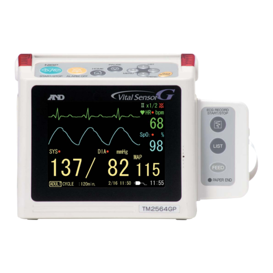
Page 17: Part Names
3. Part Names 3-1 TM-2560G/TM-2564G... -
Page 18: Tm-2560Gp/Tm-2564Gp
3-2 TM-2560GP/TM-2564GP... -
Page 19: Top Operation Panel
3-3 Top Operation Panel Name Function NIBP START/STOP key Starts or stops the blood pressure measurement. ALARM OFF key Stops the alarm buzzer. (Refer to "6-10 Alarm function".) Selects a home display to be displayed. HOME key Returns to the home display when the list, trend or setting mode is displayed. -
Page 20: Printer Keys
3-4 Printer Keys TM-2564GP TM-2560GP Name Function ECG RECORD Prints the ECG waveform. START/STOP key Functions as the PAUSE key when the waveform is printed. Prints the memory data in tabular form. (Refer to "6-13 Printing the LIST key Measurement Data") FEED key Feeds the paper. -
Page 21: Preparation Before Use
4. Preparation Before Use 4-1 Installation Site When installing the instrument, consider "General Precautions" appearing in an earlier part of the instruction manual. 4-2 Power Supply The instrument can be operated using an AC adapter or battery. When an AC adapter is used: 1. - Page 22 When the battery is used: 1. Remove the power cable from the electrical outlet. 2. Remove the screw from the battery compartment cover on the rear of the instrument. 3. Slide the cover to remove it. 4. Insert the battery connector into the connector port battery...
- Page 23 Charging the battery Charging starts when the AC adapter is connected to the instrument, regardless of the power switch status. It takes 15 hours to complete charging. The battery capacity lowers due to self-discharge. To compensate the capacity lost due to self discharge, intermittent charging is performed automatically.
-
Page 24: Installation Procedure
4-3 Installation Procedure Warning • Do not use damaged cables and sensors. • Use the specified cables and sensors only. • The ECG unit is protected against defibrillator discharge only when the supplied ECG extension cable is used. 1. Confirm that the power switch is turned off. -
Page 25: Displays
5. Displays 5-1 Home Display Press the HOME key to indicate the home display. There are six home display types 1. Blood pressure 2 traces (Default display) 6. Sleep mode Emphasizes the blood pressure values Blank display 2. Waveform 2 traces 5. - Page 26 Displayed items depend on the display screen selected. Below is a list of displayed items for each display. Home display Waveform Blood Pulse HR/PR Temperature Message pressure graph Blood ⎯ ⎯ ⎯ pressure 2 Large Medium (3.2 seconds) traces Waveform ⎯...
- Page 27 Description of the home display Here, the basic parameters are described as they appear in the home display. Please note that the composition depends on the instrument model. TM-2564G standard home display (Blood pressure 2 traces) TM-2564G Pulse graph...
- Page 28 Name Displayed item Description •Displays the value after measurement. Systolic blood pressure •Retained until the next measurement. •Flashes in red when the limit values are exceeded. Systolic blood pressure •Retained until the next measurement. (When an alarm occurs) •Flashes the error code when an error occurs. Blood pressure error •Retained until the next measurement.
- Page 29 Continued •Updates the value during measurement. •Displays " - - - " during pulse detection, and "LF" value when the sensor is not connected. •Flashes in red when the limit values are exceeded. value display •Retained until the value is within the limit values. (When an alarm occurs) •Displayed as the unit of SpO "%"...
- Page 30 Continued •Displays the connection status with the options and Message box Message other messages. •Displayed when "ON" is selected for pacemaker Pacemaker Pacemaker detection detection detection. •Displays the bar graph in synchronization with the pulse bar pulse bar graph graph display pulse.
-
Page 31: List Display
5-2 List Display When the home display is being shown, press the LIST key ( key) to go to the list display. Note • When the list display is being shown, press the HOME key to return to the home display. •... -
Page 32: Trend Display
5-3 Trend Display When the home display is being shown, press the TREND key ( key) to indicate the trend display of the latest 24 hours. Note • When the trend display is being shown, press the HOME key to return to the home display. •... -
Page 33: Pause Display
•Displays the power currently used. Power supply Power supply •Displays the remaining battery charge. display type •Displays the current time. Current time Current time display 5-4 Pause Display When the home display is being shown, press the PAUSE key to pause the waveform. Note •... -
Page 34: Setting Mode Display
5-5 Setting Mode Display When the home display is being shown, press the MENU key ( key) to indicate the setting mode display. Note • When the setting mode display is being shown, press the HOME key to return to the home display. •... -
Page 35: Quick Setting Window
5-6 Quick Setting Window When the home display is being shown, press the QUICK SETTING key to open the quick setting window. Note • When the quick setting window is being shown, press the HOME key to close the window. Refer to "6-4 Quick Setting Mode"... -
Page 36: Operation
6. Operation 6-1 Turning on the POWER switch Turn the POWER switch on. After several seconds of self-check, the home display appears. Note • When the self-check detects any error, the error code is displayed. The error code display of some errors is frozen. - Page 37 Attaching the ECG electrodes Warning Check the electrode attaching condition in a certain time interval. If skin integrity changes, move the sensor to another site. Caution • Before attaching the electrodes, use alcohol to clean the body sites where the electrodes are to be attached.
- Page 38 Applying the SpO sensor Use the sensor appropriate for the patient. Refer to the instruction manual for each SpO sensor for how to apply the sensor. Warning • Read the SpO sensor instruction manual for proper use. • Applying the sensor on a body part other than specified or using it longer than specified may cause the patient to suffer physical injury.
-
Page 39: Setting Mode
6-3 Setting Mode Here, various setting procedures are described. The items available for setting depends on the model. Basic operation Menu Sub menu Set value 1. In the home display, press the MENU key ( key) to indicate the setting mode display.. 2. - Page 40 5. Press the key to change the value. 6. The changed value is confirmed when: Moved to the next menu or sub menu. The HOME key is pressed to return to the home display. Note • In the setting mode display, after about 5 minutes of inoperation, the home display will be indicated. •...
- Page 41 Continued Sets the display gain of the ⎯ Gain x1/2, x1, x2, x4 ECG waveform. Sets the sweep rate of the Time base 6.25.12.5, 25.0 mm/s ECG waveform. Also applied to the plethysmograph. Lead l, ll, lll Sets the ECG lead. ⎯...
-
Page 42: Quick Setting Mode
6-4 Quick Setting Mode Here, the quick setting mode is described, to change the values that are frequently used, or to change the values while watching the waveform. The items available for setting depend on the model. Basic operation Quick setting window Set value 1. -
Page 43: Measuring The Blood Pressure
Menu Sub menu Setting range Unit Description OFF, CON, 2.5, 3, 5, 10, Sets the cycles for interval Cycle 15, 20, 30, 60, 90, 120 measurement. Sets the pressurization value for blood pressure measurement. NIBP "AUTO": Detects the pulse at Pressurization AUTO, 100-260 (by 20) mmHg... -
Page 44: Measuring The Ecg
Interval measurement 1. Set the cycle to a value other than "OFF". 2. "CYCLE:∗∗∗" appears at the bottom of the home display and starts the interval measurement. 3. Blood pressure starts to be measured at the exact-time synchronized with the built-in clock. 4. -
Page 45: Measuring The Spo
6-7 Measuring the SpO 1. Turn on the POWER switch to start the SpO measurement. Note • In SpO measurement, the function of automatically compensating the LED to obtain suitable emission for the patient works. Thus, it may take approximately 30 seconds to display the measured value. •... -
Page 46: Alarm Function
6-10 Alarm Function When the limit values are set, the limit mark appears in red as shown in the Limit mark illustration. When the measurement value exceeds the upper or lower limit value, the value and the alarm lamp flash, and the alarm buzzer sounds. The alarm buzzer can be stopped by pressing the ALARM OFF key. - Page 47 Deleting the data 1. In the home display, press the key to go to the list display. 2. Press the key to indicate the memory deletion display. 3. Press the key to cancel the deletion and return to the list display. 4.
-
Page 48: Power Supply
6-12 Power Supply The power supply information, as shown below, appears at the lower right side of the display. Power supply symbol Description The instrument is working on the AC adapter. The instrument is working on the battery. • The battery charge is full. The instrument is working on the battery. - Page 49 Printing the ECG waveform When the ECG RECORD START/STOP key is pressed in other than the setting mode display, an ECG waveform of 16 seconds is printed. It takes about 30 seconds to print it out. With the waveform, the date, time and HR (heart rate), taken when the ECG RECORD START/STOP key is pressed, is printed.
- Page 50 Trend printing Prints the measurement data in trend form, using the symbols below: = Systolic, Diastolic = SpO , x = heart rate/pulse rate, + = temperature ECG waveform...
-
Page 51: Function Setting
6-14 Function Setting Here, the function setting procedure is described. Note • The settings can be changed to suit to the operating environment. • Turning off the POWER switch during the setting operation will cancel the operation. Setting procedure 1. While holding down the QUICK SETTING key, turn on the POWER switch to indicate the function setting display. - Page 52 Setting item Setting range Description Station address 0-98 (0) To connect an option. To connect an option. Communication mode 1-10 (1) To be selected, depending on the option. 1200, 2400, 4800, To connect an option. Baud rate 9600, 19200, 38400 To be selected, depending on the option To connect an option.
-
Page 53: Maintenance
7. Maintenance 7-1 Cleaning Caution • Before cleaning, turn off the power and remove the AC adapter. • Do not pour water on the instrument or use water for cleaning. This instrument is not waterproof. • Do not sterilize the instrument by gaseous sterilization or using an autoclave. •... -
Page 54: Calibration
7-2 Calibration This is a precision instrument. Perform a checkup periodically. Checking the pressure accuracy Connect the pressure generator and the manometer to the instrument as shown in the illustration. Use the optional 500-cc cylinder or the cuff wrapped loosely around a cylinder. 500-cc cylinder Instrument (Cuff) -
Page 55: Assembling The Cuff
7-3 Assembling the Cuff Replacing the cuff cloth Insert the rubber hose completely into the cuff cloth. From the bladder opening, pull out the bladder with the rubber hose. After replacing the cuff cloth, put back the bladder and the rubber hose through the bladder opening. Pull out the rubber hose through the rubber hose opening. -
Page 56: Error Codes
7-6 Error Codes When the instrument detects an erroneous measurement condition, the following error codes are displayed. Error code Symptom Remedy Blood pressure related errors Zero point error in the pressure Exhaust air from the cuff and turn on the power sensor circuit again. -
Page 57: Accessories/Options
8. Accessories/Options Item Type Cuff (without hose) Neonate 10 pcs. 2 cm wide TM9155 Neonate 10 pcs. 3 cm wide TM9156 Disposable type Neonate 10 pcs. 4 cm wide TM9157 Neonate 10 pcs. 5 cm wide TM9158 Infant Arm circumference 7-12 cm TM9114B-1 Child... -
Page 58: Appendix A: Measuring Principle
Appendix A: Measuring Principle A-1 Blood Pressure Measuring principle Wrap the cuff around the upper arm. Inflate the cuff to a pressure exceeding the systolic blood pressure. Then, exhaust the air from the cuff gradually. While the pressure is detected in the cuff in the air exhaustion stage, the pulse waveform appears in synchronization with the heart rate. - Page 59 Causes of errors The pulse during blood pressure measurement is indicated in a graph, which can be an objective indicator of the reliability in the measurement accuracy. When noises occur due to irregular heart rhythm or physical movements, the amplitude changes abnormally in the graph. When it happens, blood pressure should be measured again, or be checked using other methods.
-
Page 60: Spo
A-2 SpO Measuring principle Oxygen, bound to hemoglobin, is carried by blood. Hemoglobin that is bound to oxygen is called oxygenated hemoglobin (HbO ), and that is not bound to oxygen is called reduced hemoglobin (Hb). Arterial oxygen saturation is the percentage of oxygenated hemoglobin in the blood. Arterial oxygen saturation = HbO / (Hb+ HbO Oxygen-rich arterial blood is red while venous blood... - Page 61 Causes of errors In the pulse oximeter, adequate waveform implies the reliability. Always check the plethysmograph or bar graph for noises and disturbances. When noises or disturbances occur, check the probe Plethysmograph connection or patient condition. The following are the main causes of errors in arterial oxygen saturation measurement.
-
Page 62: Appendix B: External Dimensions
Appendix B: External Dimensions TM-2560G / TM-2564G TM-2560GP / TM-2564GP Unit: mm...
Need help?
Do you have a question about the TM-2564G and is the answer not in the manual?
Questions and answers