Table of Contents
Advertisement
Quick Links
Advertisement
Table of Contents

Related Manuals for A&D AD4329A-DLC


Summary of Contents for A&D AD4329A-DLC
- Page 1 AD4329A-DLC Weighing Indicator INSTRUCTION MANUAL 1WMPD4003952...
-
Page 2: Table Of Contents
7.4. Push zero .............................. 28 7.5. Zero tracking ............................28 7.6. Power-on zero............................28 7.7. Zero detection ............................28 7.8. Stability detection ..........................28 7.9. Tare............................... 29 7.10. Preset tare............................29 7.11. Accumulation............................30 7.12. High Resolution........................... 31 AD4329A-DLC Page 2... - Page 3 13.2.2. External control input........................56 13.2.3. Comparator output ........................57 13.2.4. Standard serial output ........................57 13.2.5. RS-232C interface........................58 13.3. CF-function setting method......................... 59 13.4. CF-function list ............................ 60 14. Check the Software Version ........................62 15. Specifications............................. 63 Page 3 AD4329A-DLC...
-
Page 4: Introduction
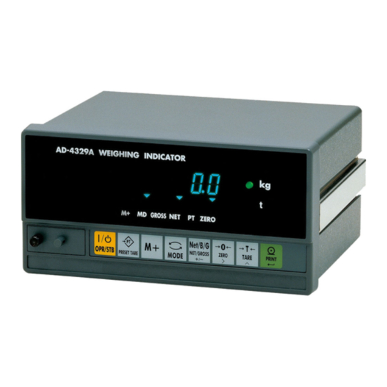
AD4329A-DLC is a digital load cell weighing indicator that enables use of truck scales. By combining the AD4329A-DLC with an A&D digital load cells (LCCD20 series), a weighing system with higher lightning resistance performance can be built, and electronic corner adjustment can be performed easily and precisely. -
Page 5: Safety Precautions
● Do not clamp control wires or communication cables with power lines, and do not place them close to power lines. ● Place the load cell cable sufficiently away from high frequency circuits such as high voltage power lines and inverter load circuits. Page 5 AD4329A-DLC... -
Page 6: Part Names
Selects the place of the digit when setting the value. Tare key Performs tare. Specifies the value for the selected digit when setting a value. Print key Outputs data. Finalizes data entry and saves the set value. AD4329A-DLC Page 6... -
Page 7: Rear Panel
Fuse holder External control input connector Standard serial output connector RS-232C I/F connector Option 02 (comparator output) slot 2.3. Accessories Name Qty. Instruction Manual Connector for external control input Connector for standard serial output Spare fuse Rubber foot Page 7 AD4329A-DLC... -
Page 8: Connecting To Power Supply
AC power input (Neutral) Earthed conductive part Ground terminal The test below is performed for lightning resistance performance of the AD4329A-DLC. Impulse withstand voltage test (in the air) JEC-0202 conformity to impulse voltage and current test Standard lightning impulse voltage 1000kV 3.2. -
Page 9: Connecting To Digital Load Cells
Use an M3 solderless terminal with a width of 6.2 mm or less. Terminal No. Symbol Description SHILD Shield POW+ Load cell excitation voltage + POW- Load cell excitation voltage - DATA+ Load cell data + DATA- Load cell data - Page 9 AD4329A-DLC... -
Page 10: Connection Diagram
When you connect the digital load cells in parallel, use a junction box for digital load cells. Connecting the weighing indicator to four digital load cells is as shown below. Recommended cable is AX-KO3217 (A&D). Junction Box AD4388-4 Data - Data + Power - Power + Shield AD4329A-DLC Page 10... -
Page 11: When Connecting More Than 6 Load Cells
R W G B Y R W G B Y R W G B Y Cut the jumper (JP1). AD4388-4 R W G B Y R W G B Y R W G B Y R W G B Y Page 11 AD4329A-DLC... -
Page 12: Digital Load Cell Presetting
Change the value of the flashing digit. [PRINT]: Update to the new value and return to the item selection. [MODE]: Cancel the value setting and return to the item selection. Change " 4 Update Cancel Cf-10" 1 AD4329A-DLC Page 12... -
Page 13: Serial Number Settings Of Digital Load Cells
Before operation, check the serial number on the digital load cell. And set the serial number specified for each digital load cell to the AD4329A-DLC. When your weighing scale is built using four digital load cells, the serial numbers for four units must be set. - Page 14 Change Move [MODE]: Cancel the value setting and return to the item selection. 290041" 4 Update Cancel Set the serial numbers for all of the digital load cells connected by using the same procedure. Cf-10" 2 Confirm AD4329A-DLC Page 14...
-
Page 15: Calibration
6. Calibration Calibrate the AD4329A-DLC so that it can properly convert the signal from the load cell to a mass value. Set or execute the following items required for calibration. ・ Scale interval (resolution) setting ・ Maximum capacity setting ・ Four corner adjustment ・... - Page 16 " 9 798 Maximum CanCel capacity setting Multi-interval function C " 1 0000 Cap2-02 Cancel Zero calibration Four corner adjustment Cal 0 4C Cal0 Span calibration Linearity calibration f " 1 0000 lnr 1 AD4329A-DLC Page 16...
-
Page 17: Scale Interval Setting
Change the value of the flashing digit. [ZERO]: Move the flashing digit. [PRINT]: Confirm the changed value and go to the next item. Change Move Skip [MODE]: Skip this item and go to the next item. C 1" 2 000 Confirm Next page Page 17 AD4329A-DLC... -
Page 18: Zero Compensation At Four Corner Adjustment
Set an adjustment weight value for corner adjustment by the following 10000 key operations. [TARE]: Change the value of the flashing digit. [ZERO]: Move the flashing digit. Change Move [PRINT]: Update to the new value and go to the next item. " 1 000 Update Next page AD4329A-DLC Page 18... -
Page 19: Four Corner Adjustment
Execute corner adjustment for all of the load cells connected by using the same procedure. After that, the display proceeds as shown in the example at 4C end the right. For 2 seconds Cal 0 Next page Page 19 AD4329A-DLC... -
Page 20: Zero Calibration
If the calibration was done successfully, "CAL End" is displayed. Pressing [CAL] finishes the calibration and "End" is displayed. Cal end Pressing [MODE] returns to scale interval setting again. d-01 Pressing [OPR/STB] twice goes to weighing mode. 0. 0 0 AD4329A-DLC Page 20... -
Page 21: Multi-Interval Function
When the net value is between 20 and 50kg, 2nd range (Interval 0.02kg) is selected. When the net value is between 50 and 60kg, 3rd range (Interval 0.1kg) is selected. Interval 0.1kg Interval 0.02kg Interval 0.01kg Interval 0.02kg Tare -40kg -20kg 20kg 50kg 60kg Gross 20kg 40kg 60kg 100kg Page 21 AD4329A-DLC... -
Page 22: Scale Interval And Capacity Settings For Each Range
C " 1 0000 C " 2 000 C " 1 0000 Change Move the value the digit C " 2 000 C " 5 000 C " 2 0000 place Zero calibration Cal 0 AD4329A-DLC Page 22... -
Page 23: Linearity Calibration
・ Calibration for compensation point 3 (If necessary) Before compensation After compensation Span calibration point Display Display Digital load cell output Comp point 3 Comp point 2 Error Comp point 1 Linearity adjustment Ideal value Load Load Zero calibration point Zero calibration point Page 23 AD4329A-DLC... - Page 24 Delete compensation point 3 to go to span calibration. Change Move Place the adjustment weight on the scale. When the MD mark illuminates, press [PRINT] to execute adjustment for point 3. l " 7 500 Execute f " 1 0000 AD4329A-DLC Page 24...
-
Page 25: Gravitational Acceleration Compensation
Change the value of the flashing digit. [ZERO]: Move the flashing digit. g2 979" 1 [PRINT]: Update the displayed value as the gravitational acceleration of the usage location. Update g1 980" 6 After setting, press [CAL] to move to standby mode. Page 25 AD4329A-DLC... -
Page 26: Error Display
Shows that the weight values set at four corner adjustment are smaller than the scale interval. Shows that the value is below zero point even after placing the weight at four corner err 7 adjustment. Pressing [MODE] returns to the previous step. AD4329A-DLC Page 26... -
Page 27: Basic Weighing Function
7. Basic Weighing Function 7.1. Weighing mode When the AD4329A-DLC is turned on, all the segment of the display illuminate/extinguish for checking the display. Then the AD4329A-DLC is in weighing mode and starts weighing. The contents in the display in weighing mode are as follows. -
Page 28: Display Off (Standby Mode)
Center of zero is detected and the ZERO mark illuminates when the gross value is within 1/4 of the scale interval. 7.8. Stability detection Stability is detected and the MD mark illuminates when the weight value meets the stability detection condition (F- 02). AD4329A-DLC Page 28... -
Page 29: Tare
The current preset tare value is displayed with the preset tare mark illuminated. Press [ZERO] to move the flashing digit. Press [TARE] to change the value of the flashing digit. Press [PRINT] to update the preset tare value to go to weighing mode and display the net value. Page 29 AD4329A-DLC... -
Page 30: Accumulation
● Display total value Press [MODE] in weighing mode. After "total" is displayed, the total value is displayed with M+ mark flashing. Press [MODE] again to go to weighing mode. It is not possible to display the accumulation count. AD4329A-DLC Page 30... -
Page 31: High Resolution
The gross value is displayed with resolution of 10 or higher. High resolution can be used for test purposes. Press [CAL] in weighing mode. Press [MODE] while "CAL in" is shown in the display. The gross value with high resolution will appear in the display. Press the [OPR/STB] to return to weighing mode. Page 31 AD4329A-DLC... -
Page 32: External Control Input
M+ key Pin 5 (F-13) NET / GROSS key Pin 6 (F-14) MODE key Pin 7 (F-15) ON= net / OFF= gross is displayed Pin 8 (F-16) Display the total value Display overload Release the key lock (F-06) AD4329A-DLC Page 32... -
Page 33: Standard Serial (Current Loop) Output
Shell Frame ground Communication specifications Signal level Current loop 0..20 mA Baud rate(F-34) 0:600、1:1200、2:2400 bps Data bit length 7 bits Parity Even Start bit length 1 bit Stop bit length 1 bit Code ASCII Terminator CR LF Page 33 AD4329A-DLC... - Page 34 When the MD mark is illuminated, weighing data is output. Once output, it will not be possible to output again until the displayed value is within output inhibition range (F-32) Manual print When [PRINT] is pressed with the MD mark illuminated, weighing data is output. AD4329A-DLC Page 34...
-
Page 35: Output Data Format
*1) It is possible to select the number of digits and decimal point format for output data (CF-010). 0: Two digits, "." dot 1: Three digits, "." dot 2: Two digits, "," comma 3: Three digits, "," comma Page 35 AD4329A-DLC... -
Page 36: Comparator Output (Option-02)
・ F-20 = 1, F-21 = 2 (not compared when the displayed value is +5d or less.) ・ Upper limit value = 3000, lower limit value = 500 Conditions Displayed value > 3000 3000 Displayed value 500 500 > Displayed value > 5 5 Displayed value AD4329A-DLC Page 36... - Page 37 Example: Input 500 to set 50.0 for the lower limit Change Move [TARE]: Move the flashing digit. [ZERO]: Change the value of the flashing digit. Polarity Skip [NET/GROSS]: Switch the polarity. [PRINT]: Update the value " 5 00 [MODE]: Skip the lower limit value. Update Page 37 AD4329A-DLC...
- Page 38 Install the comparator output option to the rear panel with two M3 screws. Connect the 5-wire cable between the option board and J5 on the main board. Assemble all parts except the blank panel by the reverse procedure.. The blank panel is not used. AD4329A-DLC Page 38...
-
Page 39: Rs-232C Interface
11. RS-232C Interface RS-232C interface is used to connect the AD4329A-DLC to a PC or PLC. The applicable connector is a 9-pin D-sub female with inch screws. The connector is not provided and must be prepared by the user. Pin No. - Page 40 When [PRINT] is pressed with the MD mark illuminated, weighing data is output. Command When a command is received from the master (PC or PLC), data will be read, functions will be executed, or data will be written. AD4329A-DLC Page 40...
-
Page 41: Output Data Format
1: Three digits, "." dot 2: Two digits, "," comma 3: Three digits, "," comma ● F-45 = 1: format 2 <CR> <LF> Weighing data Terminator If overload appears on the display, +99999999 without the decimal point will be output. Page 41 AD4329A-DLC... -
Page 42: Command Format
Write a lower limit value (Command shown at the left will write +560.) ・ Error response I<CR><LF> Response to an unacceptable command. ?<CR><LF> The command is incorrect. ・ Communication example Master AD4329A-DLC RW<CR><LF> Response for the displayed value ST,G<SP>,+01234.5kg<CR><L MT<CR><LF> Taring execution MT<CR><LF> PT,+213<CR><LF>... -
Page 43: Confirming And Initializing The Operations And Setting Values
CHc " f " - CHc1" C " l Confirmation of RS-232C Confirmation of the comparator output CHc " r " 5 CHc1" o " U " t Confirmation of each operation Confirmation of each setting value Initialization Page 43 AD4329A-DLC... -
Page 44: Confirming The Digital Load Cell
After displaying "lC4load" for 2 seconds, the actual load applied to the load cell is displayed. After displaying "lC4 4C" for 2 seconds, the value calibrated is displayed. After displaying "lC4 temp" for 2 seconds, the internal 26. 2 temperature (℃) is displayed. AD4329A-DLC Page 44... -
Page 45: Confirming The Keys
12.2. Confirming the keys Press the each key to switch the corresponding "o" to "1". 2 seconds later CHc1yey oooooo 1ooooo o1oooo oo1ooo ooo1oo oooo1o ooooo1 2 seconds later Page 45 AD4329A-DLC... -
Page 46: Confirming The External Control Input
EXT2 oooo1o EXT3 ooo1oo EXT4 oo1ooo EXT5 o1oooo EXT6 1ooooo 12.4. Confirming the standard serial output CHc1Cl Press [PRINT] to transmit ST,G,+00000.0kg<CR><LF>. Communication specifications depend on settings for F-30 to F-34. Cl 5end 2 seconds later AD4329A-DLC Page 46... -
Page 47: Confirming The Comparator Outputs
5end When receiving data, the first four characters are displayed. Transmit The example at the right is when A123<CR><LF> is received. Communication specifications depend on settings for F-40 to F-47. r5 a123 2 seconds later Receive Page 47 AD4329A-DLC... -
Page 48: Confirming The F Function Setting Values
Operate the following keys to select the items to be confirmed. Cf-00" 0 [TARE]: Change the value of the flashing digit. [ZERO]: Move the flashing digit. Change [PRINT]: Display the setting value for the currently displayed item. Move Cf-10" 0 2 seconds later AD4329A-DLC Page 48... -
Page 49: Confirming The Calibration Setting Values
Weight values at four Gravitational acceleration corner adjustments compensation 1 grav1 4C Calf Gravitational acceleration Maximum capacity compensation 2 grav2 CalC Weight values at span Load cell output at calibration zero calibration Calf Cal0 Confirmation of each setting value Page 49 AD4329A-DLC... -
Page 50: Confirming The Scale Interval (Resolution)
2 seconds. grav1 9798 12.9.4. Confirming the gravitational acceleration compensation 1 Press [PRINT] to proceed to the next confirmation item after displaying the To next page setting value for gravitational acceleration compensation 1 for 2 seconds. AD4329A-DLC Page 50... -
Page 51: Confirming The Gravitational Acceleration Compensation 2
2 seconds. 2 seconds later CalC 12.9.8. Confirming the maximum capacity 10000 Press [PRINT] to proceed to the next confirmation item after displaying the maximum capacity for 2 seconds. 2 seconds later To next page Page 51 AD4329A-DLC... -
Page 52: Confirming The Weight Value At Four Corner Adjustments
Operate the following keys to select the item to be confirmed. [TARE]: Change the load cell to be confirmed. [PRINT]: Return to previous display after displaying lC" 4 the compensation value for 2 seconds. 1. 0 00000 2 seconds later AD4329A-DLC Page 52... -
Page 53: Initializing
" i " n " i " t " f " n init. f nC Press and hold Initialization of all data initall " i " n " i " t " a " l init. a ll Page 53 AD4329A-DLC... -
Page 54: Function Setting
Change the value of the flashing digit. Confirm [PRINT]: Update to the new value and return to the item selection. f-31 " 0 [MODE]: Cancel the changed value and return to Update the item selection. Move Change Cancel f-31 " 2 AD4329A-DLC Page 54... -
Page 55: F-Function List
[OPR/STB] key [PRESET TARE] key If you lock [OPR/STB], turn on the power [M+] key while pressing and holding [OPR/STB] and [MODE] key [MODE] to go to F-function mode. [NET/GROSS] key [ZERO] key [TARE] key [PRINT] key Page 55 AD4329A-DLC... -
Page 56: External Control Input
[ZERO] key EXT2 (Pin3) [TARE] key EXT3 (Pin4) [PRINT] key EXT4 (Pin5) [OPR/STB] key EXT5 (Pin6) [M+] key EXT6 (Pin7) [NET/GROSS] key EXT7 (Pin8) [MODE] key Display ON=NET/OFF=GROSS Display total value Display overload Release key lock (F-06) AD4329A-DLC Page 56... -
Page 57: Comparator Output
Gross + Net + Tare value Communication mode Stream Auto print Manual print Auto print inhibition range +5 d or less Within ± 5 d Data interval at F-30=4 None 2 seconds Baud rate 600 bps 1200 bps 2400 bps Page 57 AD4329A-DLC... -
Page 58: Rs-232C Interface
Auto print inhibition range +5 d or less Within ± 5 d Data interval at F-40=4 None 2 seconds Baud rate 600 bps 1200 bps 2400 bps 4800 bps 9600 bps Data format Data format 1 Data format 2 Reserved AD4329A-DLC Page 58... -
Page 59: Cf-Function Setting Method
Change the value of the flashing digit. 000000" 0 [PRINT]: Update to the new value and return to the item selection. Cancel [MODE]: Cancel the new value and return to the item Move Change selection. " 1 234567 Page 59 AD4329A-DLC... -
Page 60: Cf-Function List
Two digits, "," comma Three digits, "," comma 011 Accumulation function Disable Enable 012 Overload condition on negative gross value. Gross < - Maximum capacity Gross < -20d 013 Manually print at negative gross value. Enable Disable AD4329A-DLC Page 60... - Page 61 CF- Item Setting value Default User setting 100 Number of digital load cells 1 to 8 Serial number of each 0000000 to 9999999 000000 digital load cell Page 61 AD4329A-DLC...
-
Page 62: Check The Software Version
14. Check the Software Version Press [OPR/STB]. 0. 0 0 OPR/STB mode While pressing and holding [MODE], press [OPR/STB]. Press [MODE]. f-0" 1 The software version will appear. r 100 Press [OPR/STB] twice to back to weighing mode. AD4329A-DLC Page 62... -
Page 63: Specifications
External input / output External control input Non-voltage contact input 7: points 8-pin DIN connector RS-232C interface 9-pin D-sub male with inch screws Standard serial output 7-pin DIN connector Option Comparator output Mechanical relay output: 3 points Page 63 AD4329A-DLC... - Page 64 External Dimensions Panel cut dimensions Panel thickness: 1.6 to 3.2 Unit:mm AD4329A-DLC Page 64...
- Page 65 3-23-14 Higashi-Ikebukuro, Toshima-ku, Tokyo 170-0013, JAPAN Telephone: [81] (3) 5391-6132 Fax: [81] (3) 5391-1566 A&D ENGINEERING, INC. 1756 Automation Parkway, San Jose, California 95131, U.S.A. Telephone: [1] (408) 263-5333 Fax: [1] (408)263-0119 A&D INSTRUMENTS LIMITED Unit 24/26 Blacklands Way, Abingdon Business Park, Abingdon, Oxfordshire OX14 1DY United Kingdom Telephone: [44] (1235) 550420 Fax: [44] (1235) 550485 A&D AUSTRALASIA PTY LTD...
Need help?
Do you have a question about the AD4329A-DLC and is the answer not in the manual?
Questions and answers