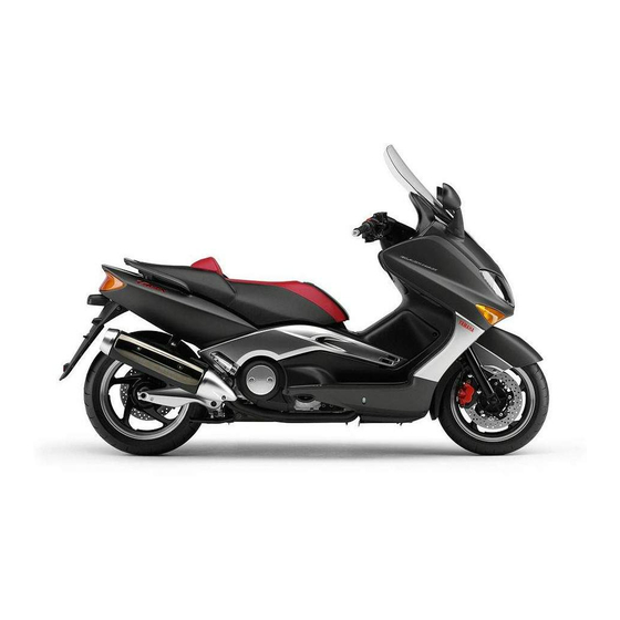
Yamaha TMAX XP500 Owner's Manual
Hide thumbs
Also See for TMAX XP500:
- Service manual (559 pages) ,
- Owner's manual (104 pages) ,
- Technical manual (46 pages)

Related Manuals for Yamaha TMAX XP500


Summary of Contents for Yamaha TMAX XP500
- Page 1 Read this manual carefully before operating this vehicle. OWNER’S MANUAL XP500 XP500A 59C-28199-E1...
-
Page 2: Declaration Of Conformity
Read this manual carefully before operating this vehicle. This manual should stay with this vehicle if it is sold. YAMAHA MOTOR ELECTRONICS CO., LTD. 1450-6, Mori, Mori-machi, Shuchi-gun, Shizuoka-ken, 437-0292 Japan DECLARATION of CONFORMITY Company: YAMAHA MOTOR ELECTRONICS CO., LTD. Address: 1450-6, Mori, Mori-Machi, Shuchi-gun, Shizuoka-Ken, 437-0292 Japan Hereby declare that the product: Kind of equipment: IMMOBILIZER... - Page 3 Yamaha a reputation for dependability. Please take the time to read this manual thoroughly, so as to enjoy all advantages of your XP500/XP500A. The Owner’s Manual does not only instruct you in how to operate, inspect and maintain your scooter, but also in how to safeguard yourself and others from trouble and injury.
- Page 4 IMPORTANT MANUAL INFORMATION EAU10133 Particularly important information is distinguished in this manual by the following notations: This is the safety alert symbol. It is used to alert you to potential personal injury hazards. Obey all safety messages that follow this symbol to avoid possible injury or death.
- Page 5 IMPORTANT MANUAL INFORMATION EAU10200 XP500/XP500A OWNER’S MANUAL ©2012 by Yamaha Motor Co., Ltd. 1st edition, June 2012 All rights reserved. Any reprinting or unauthorized use without the written permission of Yamaha Motor Co., Ltd. is expressly prohibited. Printed in Japan.
-
Page 6: Table Of Contents
TABLE OF CONTENTS SAFETY INFORMATION ....1-1 Rear view mirrors ......3-25 Adjusting the engine idling Further safe-riding points ....1-5 Shock absorber assembly .... 3-26 speed ......... 6-16 Sidestand ........3-26 Checking the throttle grip free DESCRIPTION ........2-1 Ignition circuit cut-off system .. - Page 7 TABLE OF CONTENTS Tail/brake light ......6-33 Replacing a front turn signal light bulb ........... 6-33 Rear turn signal light bulb....6-34 Replacing the license plate light bulb ........... 6-34 Replacing an auxiliary light bulb ... 6-35 Troubleshooting ......6-35 Troubleshooting charts ....
-
Page 8: Safety Information
SAFETY INFORMATION EAU1026A training course. Beginners • Use extra caution when you are should receive training from a cer- approaching passing tified instructor. Contact an autho- through intersections, since in- Be a Responsible Owner rized scooter dealer to find out tersections are the most likely As the vehicle’s owner, you are respon- about the training courses nearest... - Page 9 SAFETY INFORMATION tice riding your scooter where with both hands and keep both control levers or wheels and cause there is no traffic until you have feet on the passenger footrests. injury or an accident. become thoroughly familiar with Never carry a passenger unless Always wear protective clothing the scooter and all of its con-...
- Page 10 Securely as windows and doors. Yamaha accessories, which are avail- pack your heaviest items as close able only from a Yamaha dealer, have to the center of the vehicle as pos- Loading been designed, tested, and approved...
- Page 11 Yamaha accessories, recog- namic changes. If accessories lights or engine power. nize that some aftermarket accessories are added to the handlebar or...
-
Page 12: Further Safe-Riding Points
SAFETY INFORMATION to solid parts of the scooter, such EAU10373 and ankle so they do not flap), and Further safe-riding points as the frame or upper front fork tri- a bright colored jacket. Be sure to signal clearly when ... -
Page 13: Description
DESCRIPTION EAU10410 Left view 9 8 7 6 1. Battery (page 6-28) 8. Engine oil drain bolt (page 6-11) 2. V-belt air filter element (left) 9. Engine oil level check window (page 6-11) 3. Helmet holder (page 3-21) 10.Oil filter cartridge (page 6-11) 4. -
Page 14: Right View
DESCRIPTION EAU10420 Right view 1. Owner’s tool kit (page 6-2) 2. Fuel tank cap (page 3-17) 3. Air filter element (page 6-15) 4. Windshield (page 3-24) 5. Fuses (page 6-30) 6. V-belt air filter element (right) 7. Centerstand (page 6-26) -
Page 15: Controls And Instruments
DESCRIPTION EAU10430 Controls and instruments 1. Rear brake lever (page 3-14) 8. Front brake lever (page 3-14) 2. Left handlebar switches (page 3-12) 9. Throttle grip (page 6-17) 3. Rear brake lock lever (page 3-15) 10.Front storage compartment B (page 3-22) 4. -
Page 16: Instrument And Control Functions
a Yamaha dealer to have them re-reg- Do not place any key close to istered. Do not use the key with the red magnets (this includes, but not bow for driving. -
Page 17: Main Switch/Steering Lock
INSTRUMENT AND CONTROL FUNCTIONS ference. EAU10472 come on, and the engine can be start- Main switch/steering lock ed. The key cannot be removed. The headlight comes on automatically when the engine is started and stays on until the key is turned to “OFF” or the sidestand is moved down. -
Page 18: Indicator Lights And Warning Lights
4. Engine trouble warning light “ ” a Yamaha dealer check the electrical The steering must be locked before the 5. Immobilizer system indicator light circuit. key can be turned to “... - Page 19 The ABS may not work correctly. If any but this does not indicate a mal- of the above occurs, have a Yamaha function. dealer check the system as soon as possible. (See page 3-16 for an expla- nation of the ABS.)
-
Page 20: Speedometer
INSTRUMENT AND CONTROL FUNCTIONS EAU11601 EAU11872 EAU52242 Speedometer Tachometer Multi-function display EWA12312 WARNING Be sure to stop the vehicle before making any setting changes to the multi-function display. Changing settings while riding can distract the operator and increase the risk of an accident. - Page 21 INSTRUMENT AND CONTROL FUNCTIONS an odometer multi-function display will appear two tripmeters (which show the one after the other and then disap- distance traveled since they were pear, in order to test the electrical last set to zero) circuits.
- Page 22 INSTRUMENT AND CONTROL FUNCTIONS V-Belt Trip Oil Trip Odo minutes. 5. Push the left set button and then release it to start the clock. Odometer and tripmeter modes 1. V-belt replacement tripmeter 1. Fuel reserve tripmeter Pushing the left set button switches the display between the odometer mode To reset a tripmeter, select it by push- and the tripmeter modes in the follow-...
- Page 23 INSTRUMENT AND CONTROL FUNCTIONS fuel meter indicates the amount of fuel (See page 6-38.) This indicator flashes at the initial 1000 in the fuel tank. The display segments km (600 mi), then at 5000 km (3000 mi) of the fuel meter disappear towards “E” and every 5000 km (3000 mi) thereafter (Empty) as the fuel level decreases.
- Page 24 (12500 mi) when the V-belt needs to be 3. If the V-belt replacement indicator neous fuel consumption mode “km/L” replaced. does not come on, have a Yamaha or “L/100 km” in the following order: After changing the V-belt, reset the dealer check the electrical circuit.
- Page 25 INSTRUMENT AND CONTROL FUNCTIONS ture display “Air”, the average fuel con- from the ambient temperature. Pushing consumption since it was last reset. sumption mode “AVE_ _._ MPG” and the right set button switches the ambi- When the display is set to “AVE_ the instantaneous fuel consumption ent temperature display to the average _._ km/L”, the average distance...
- Page 26 Yamaha dealer check the vehicle. second when one of the displays is The self-diagnosis device also detects shown (except for the UK).
-
Page 27: Anti-Theft Alarm (Optional)
2. If the engine starts, turn it off and This model can be equipped with an Left try starting the engine with the optional anti-theft alarm by a Yamaha standard keys. dealer. Contact a Yamaha dealer for 3. If one or both of the standard keys more information. - Page 28 INSTRUMENT AND CONTROL FUNCTIONS Right position. To cancel the turn signal does not indicate a malfunction. lights, push the switch in after it has re- turned to the center position. EAU12733 Hazard switch “ ” With the key in the “ON” or “ ”...
-
Page 29: Front Brake Lever
INSTRUMENT AND CONTROL FUNCTIONS EAU44911 “ ” mark on the front brake lever. EAU44921 Front brake lever Rear brake lever 1. Front brake lever 1. Rear brake lever 2. Brake lever position adjusting dial 2. Brake lever position adjusting dial 3. -
Page 30: Rear Brake Lock Lever
INSTRUMENT AND CONTROL FUNCTIONS with the “ ” mark on the rear brake le- EAU12962 rear brake lock lever is applied. Rear brake lock lever ver. To provide secure locking of the rear wheel, apply the rear brake le- ver first before moving the rear brake lock lever to the left. -
Page 31: Abs (For Abs Models)
ABS (for ABS models) ABS system. The ABS performs a self-diagno- The Yamaha ABS (Anti-lock Brake sis test each time the vehicle first System) features a dual electronic con- starts off after the key is turned to trol system, which acts on the front and “ON”... -
Page 32: Fuel Tank Cap
INSTRUMENT AND CONTROL FUNCTIONS EAU13175 move it. Fuel tank cap 3. Close the lid. EWA11261 To remove the fuel tank cap WARNING 1. Open the lid by pulling the lever up. Make sure that the fuel tank cap is properly installed and locked in place before riding the scooter. -
Page 33: Fuel
Stop filling when the fuel Gasoline is poisonous and can Your Yamaha engine has been de- reaches the bottom of the filler cause injury or death. Handle gaso- signed to use regular unleaded gaso- tube. -
Page 34: Catalytic Converter
Do not park the vehicle near recommended by Yamaha because it possible fire hazards such as can cause damage to the fuel system grass or other materials that or vehicle performance problems. easily burn. ... -
Page 35: Seat
INSTRUMENT AND CONTROL FUNCTIONS EAU13932 EAU14270 Seat Adjusting the rider backrest The rider backrest can be adjusted to To open the seat the three different positions shown. 1. Place the scooter on the center- stand. 2. Insert the key into the main switch, and then turn it counterclockwise to “OPEN”. -
Page 36: Helmet Holder
INSTRUMENT AND CONTROL FUNCTIONS EAU46300 jection, and securely close the Helmet holder seat. WARNING! Never ride with a helmet attached to the helmet holder, since the helmet may hit objects, causing loss of control and possibly an accident. [EWA10161] To release the helmet from the hel- met holder Open the seat, remove the helmet 1. -
Page 37: Storage Compartments
INSTRUMENT AND CONTROL FUNCTIONS EAU52221 To open the storage compartment Storage compartments when it is unlocked, simply pull on the lever while pushing the lever up. Front storage compartment A To open the storage compartment, pull the lid as shown. WARNING! Do not store heavy items in this compart- ment. - Page 38 (11 lb) wrap wet articles in a plastic bag be- Maximum load for the vehicle: fore storing them in the compart- XP500 198 kg (437 lb) ment. Since storage XP500A 194 kg (428 lb) 1. Rear storage compartment compartment may get wet while the 2.
-
Page 39: Windshield
INSTRUMENT AND CONTROL FUNCTIONS EAU52211 Windshield To suit the rider’s preference, the wind- shield height can be changed to one of two positions. 1. Quick fastener 1. Rubber cap 2. Screw access cover 4. Install the rubber caps in the de- 2. -
Page 40: Rear View Mirrors
INSTRUMENT AND CONTROL FUNCTIONS EAU39671 Rear view mirrors The rear view mirrors of this vehicle can be folded forward or backward for park- ing in narrow spaces. Fold the mirrors back to their original position before riding. 1. Screw 1. Screw access cover 6. -
Page 41: Shock Absorber Assembly
INSTRUMENT AND CONTROL FUNCTIONS EAU46021 EAU15305 Yamaha dealer repair it if it does not Shock absorber assembly Sidestand function properly. The sidestand is located on the left side EWA10221 WARNING of the frame. Raise the sidestand or This shock absorber assembly con-... -
Page 42: Ignition Circuit Cut-Off System
INSTRUMENT AND CONTROL FUNCTIONS EAU45052 Ignition circuit cut-off system The ignition circuit cut-off system (com- prising the sidestand switch and brake light switches) has the following func- tions. It prevents starting when the side- stand is up, but neither brake is ap- plied. - Page 43 2. Make sure that the engine stop switch is turned on. stand during this inspection. • 3. Turn the key on. If a malfunction is noted, have a Yamaha 4. Keep the front or rear brake applied. dealer check the system before riding. 5. Push the start switch.
-
Page 44: For Your Safety - Pre-Operation Checks
• If necessary, add recommended coolant to specified level. 6-14 • Check cooling system for leakage. • Check operation. • If soft or spongy, have Yamaha dealer bleed hydraulic system. • Check brake pads for wear. Front brake • Replace if necessary. - Page 45 • Make sure that operation is smooth. • Check throttle grip free play. Throttle grip 6-17, 6-25 • If necessary, have Yamaha dealer adjust throttle grip free play and lubricate cable and grip housing. • Check for damage. • Check tire condition and tread depth.
-
Page 46: Operation And Important Riding Points
a lean angle sensor to stop the en- structions prior to operating the ve- understand, ask your Yamaha dealer. gine in case of a turnover. In this hicle for the first time. EWA10271... -
Page 47: Starting Off
OPERATION AND IMPORTANT RIDING POINTS light, or indicators remains on, see ECA11042 EAU45091 Starting off NOTICE pages 3-3, 3-5, 3-8, 3-9 or 3-11 for the 1. While pulling the rear brake lever For maximum engine life, never ac- corresponding warning light, indica- with your left hand and holding the celerate hard when the engine is tor light or indicator circuit check. -
Page 48: Acceleration And Deceleration
OPERATION AND IMPORTANT RIDING POINTS EAU16780 EAU16793 Front Acceleration and deceleration Braking EWA10300 WARNING Avoid braking hard or suddenly (especially when leaning over to one side), otherwise the scooter may skid or overturn. Railroad crossings, streetcar rails, iron plates on road con- struction sites, and manhole Rear covers become extremely slip-... -
Page 49: Tips For Reducing Fuel Consumption
Yamaha dealer check the vehi- Turn the engine off instead of let- to the correct operating clearances. cle. ting it idle for an extended length of During this period, prolonged full-throt- time (e.g., in traffic jams, at traffic... -
Page 50: Parking
OPERATION AND IMPORTANT RIDING POINTS EAU17213 Parking When parking, stop the engine, and then remove the key from the main switch. EWA10311 WARNING Since the engine and exhaust system can become very hot, park in a place where pedestri- ans or children are not likely to touch them and be burned. -
Page 51: Periodic Maintenance And Adjustment
– possibly leading to pending on the weather, terrain, geo- that is certified (if applicable). Yamaha death. See page 1-2 for more in- graphical location, and individual use, dealers are trained and equipped to... -
Page 52: Owner's Tool Kit
If you do not have the tools or experi- ence required for a particular job, have a Yamaha dealer perform it for you. -
Page 53: Periodic Maintenance Chart For The Emission Control System
From 50000 km (30000 mi), repeat the maintenance intervals starting from 10000 km (6000 mi). Items marked with an asterisk should be performed by a Yamaha dealer as they require special tools, data and technical skills. EAU46910 Periodic maintenance chart for the emission control system... -
Page 54: General Maintenance And Lubrication Chart
PERIODIC MAINTENANCE AND ADJUSTMENT EAU1770E General maintenance and lubrication chart ODOMETER READING ANNUAL ITEM CHECK OR MAINTENANCE JOB 1000 km 10000 km 20000 km 30000 km 40000 km CHECK (600 mi) (6000 mi) (12000 mi) (18000 mi) (24000 mi) ... - Page 55 PERIODIC MAINTENANCE AND ADJUSTMENT ODOMETER READING ANNUAL ITEM CHECK OR MAINTENANCE JOB 1000 km 10000 km 20000 km 30000 km 40000 km CHECK (600 mi) (6000 mi) (12000 mi) (18000 mi) (24000 mi) • Check belt condition. • Replace if damaged. Every 10000 km (6000 mi) until 40000 km (24000 mi), and every ...
- Page 56 PERIODIC MAINTENANCE AND ADJUSTMENT ODOMETER READING ANNUAL ITEM CHECK OR MAINTENANCE JOB 1000 km 10000 km 20000 km 30000 km 40000 km CHECK (600 mi) (6000 mi) (12000 mi) (18000 mi) (24000 mi) • Check coolant level and vehicle ...
- Page 57 PERIODIC MAINTENANCE AND ADJUSTMENT EAU38262 Engine air filter and V-belt air filters • This model’s engine air filter is equipped with a disposable oil-coated paper element, which must not be cleaned with compressed air to avoid damaging it. • The engine air filter element needs to be replaced and the V-belt air filter elements need to be serviced more frequent- ly when riding in unusually wet or dusty areas.
-
Page 58: Removing And Installing Panels
PERIODIC MAINTENANCE AND ADJUSTMENT EAU18771 Removing and installing panels The panels shown need to be removed to perform some of the maintenance jobs described in this chapter. Refer to this section each time a panel needs to be removed and installed. 2. - Page 59 PERIODIC MAINTENANCE AND ADJUSTMENT 1. Screw 1. Screw To install the panel 2. Panel B 2. Panel C Place the panel in the original position, and then install the quick fastener. To install the panel To install the panel Place the panel in the original position, Place the panel in the original position, and then install the screws.
-
Page 60: Checking The Spark Plugs
Do not attempt to diagnose wipe off any grime from the spark plug such problems yourself. Instead, have threads. a Yamaha dealer check the vehicle. If a spark plug shows signs of electrode Tightening torque: Spark plug: erosion and excessive carbon or other 13 Nm (1.3 m·kgf, 9.4 ft·lbf) -
Page 61: Engine Oil And Oil Filter Cartridge
PERIODIC MAINTENANCE AND ADJUSTMENT installing a spark plug, a good estimate EAU1985C Engine oil and oil filter of the correct torque is 1/4–1/2 turn The engine oil should be between the cartridge past finger tight. However, the spark minimum and maximum level marks. plug should be tightened to the speci- The engine oil level should be checked fied torque as soon as possible. - Page 62 1. Oil filter wrench 2. Oil filter cartridge 1. Engine oil filler cap An oil filter wrench is available at a Yamaha dealer. 7. Apply a thin coat of clean engine oil to the O-ring of the new oil filter cartridge.
- Page 63 PERIODIC MAINTENANCE AND ADJUSTMENT ECA11620 Tightening torque: NOTICE Oil filter cartridge: In order to prevent clutch slip- 17 Nm (1.7 m·kgf, 12 ft·lbf) page (since the engine oil also 9. Install the engine oil drain bolt and lubricates the clutch), do not its new gasket, and then tighten mix any chemical additives.
-
Page 64: Coolant
PERIODIC MAINTENANCE AND ADJUSTMENT been reached), the indicator must be EAU20070 Coolant reset after the oil change for the next The coolant level should be checked periodic oil change to be indicated at before each ride. In addition, the cool- the correct time. -
Page 65: Replacing The Air Filter Element
Yamaha dealer check the anti- chart. Replace the air filter element freeze content of the coolant as more frequently if you are riding in un- soon as possible, otherwise the usually wet or dusty areas. -
Page 66: Adjusting The Engine Idling Speed
Yamaha dealer make the adjustment. direction (b). piston(s) and/or cylinder(s) may 3. Install the panel. become excessively worn. -
Page 67: Checking The Throttle Grip Free Play
Therefore, it must be adjusted by a Yamaha dealer is essential to maintain the tires in good at the intervals specified in the periodic condition at all times and replace them maintenance and lubrication chart. - Page 68 Rear: and brake-related parts, includ- 250 kPa (2.50 kgf/cm , 36 psi) ing the tires, should be left to a XP500 90–198 kg (198–437 lb) XP500A 90–194 kg (198–428 lb): 1. Tire sidewall Yamaha dealer, who has the Front: 2. Tire tread depth necessary professional knowl- 225 kPa (2.25 kgf/cm...
-
Page 69: Cast Wheels
Valve core: er damage before each ride. If any characteristics of the vehicle #9100 (original) Rear tire: damage is found, have a Yamaha may be different, which could Size: dealer replace the wheel. Do not lead to an accident. 160/60R15 M/C 67H ... -
Page 70: Checking The Front And Rear Brake Lever Free Play
PERIODIC MAINTENANCE AND ADJUSTMENT EAU50860 brake lever ends. If there is free play, Checking the front and rear have a Yamaha dealer inspect the brake lever free play brake system. EWA14211 Front WARNING A soft or spongy feeling in the brake lever can indicate the presence of air in the hydraulic system. -
Page 71: Adjusting The Rear Brake Lock Cable
Rear brake lock cable adjustment may cannot be obtained as described, maintenance and lubrication chart. be required if the rear brake lock lever have a Yamaha dealer make this ad- 1. Adjust the rear brake lock cable. does not hold properly. When the rear justment. -
Page 72: Checking The Front And Rear Brake Pads
1. Wear indicator groove cator almost touches the brake disc, 2. Wear indicator have a Yamaha dealer replace the 3. Rubber boot brake pads as a set. 1. Brake pad wear indicator Rear brake 1. -
Page 73: Checking The Brake Fluid Level
Clean the filler cap before re- fluid level goes down suddenly, have a moving. Use only DOT 4 brake fluid from a sealed container. Yamaha dealer check the cause before further riding. Use only the specified brake flu- id; otherwise, the rubber seals... -
Page 74: Changing The Brake Fluid
The drive belt slack should be checked cables brake fluid at the intervals specified in and adjusted by a Yamaha dealer at The operation of all control cables and the TIP after the periodic maintenance the intervals specified in the periodic the condition of the cables should be and lubrication chart. -
Page 75: Checking And Lubricating The Throttle Grip And Cable
Front brake lever be checked before each ride. In addi- tion, the cable should be lubricated by a Yamaha dealer at the intervals speci- fied in the periodic maintenance chart. The throttle cable is equipped with a rubber cover. Make sure that the cover is securely installed. -
Page 76: Checking And Lubricating The Centerstand And Sidestand
Yamaha dealer check or re- tenance and lubrication chart. pair it. Otherwise, the centerstand or sidestand could contact the ground... -
Page 77: Checking The Steering
2. Hold the lower ends of the front the periodic maintenance and lubrica- have a Yamaha dealer check or re- fork legs and try to move them for- tion chart. If there is play in the wheel pair it. -
Page 78: Battery
PERIODIC MAINTENANCE AND ADJUSTMENT EAU52042 medical attention. Battery Batteries produce explosive hy- The battery is located under front stor- drogen gas. Therefore, keep age compartment A. (See page 3-22.) sparks, flames, cigarettes, etc., This model is equipped with a VRLA away from the battery and pro- (Valve Regulated Lead Acid) battery. -
Page 79: To Charge/Store Battery
To charge the battery necessary. Have a Yamaha dealer charge the bat- 3. Fully charge the battery before in- tery as soon as possible if it seems to stallation. NOTICE: When install- have discharged. -
Page 80: Replacing The Fuses
PERIODIC MAINTENANCE AND ADJUSTMENT EAU54020 For XP500 For XP500A Replacing the fuses The main fuse box and the fuse box, which contains the fuses for the individ- ual circuits, are located under panel A. (See page 6-8.) If a fuse is blown, replace it as follows. - Page 81 7.5 A 10.Parking lighting fuse 3. Turn the key to “ON” and turn on the electrical circuit in question to check if the device operates. 4. If the fuse immediately blows again, have a Yamaha dealer check the electrical system. 6-31...
-
Page 82: Replacing The Headlight Bulb
6. Install the headlight bulb cover. oughly clean off any dirt and fin- 7. Install the panel. gerprints on the headlight bulb 8. Have a Yamaha dealer adjust the using a cloth moistened with al- headlight beam if necessary. cohol or thinner. -
Page 83: Tail/Brake Light
LED-type tail/brake light. 1. Place the scooter on the center- If the tail/brake light does not come on, stand. have a Yamaha dealer check it. 2. Remove the socket (together with the bulb) by turning it counter- clockwise. 1. Turn signal light bulb 2. -
Page 84: Rear Turn Signal Light Bulb
Rear turn signal light bulb Replacing the license plate If a rear turn signal light does not come light bulb on, have a Yamaha dealer check the 1. Remove the license plate light unit electrical circuit or replace the bulb. by removing the screws. -
Page 85: Replacing An Auxiliary Light Bulb
2. Auxiliary light bulb socket self. However, should your scooter re- 4. Insert a new bulb into the socket. quire any repair, take it to a Yamaha 5. Install the auxiliary light socket (to- dealer, whose skilled technicians have gether with the bulb) by pushing it... - Page 86 PERIODIC MAINTENANCE AND ADJUSTMENT heaters or furnaces. Gasoline or gasoline vapors can ignite or ex- plode, causing severe injury or property damage. 6-36...
-
Page 87: Troubleshooting Charts
Remove the spark plugs and check the electrodes. The engine does not start. Have a Yamaha dealer check the vehicle. Check the battery. 4. Battery The engine turns over The battery is good. - Page 88 Start the engine. If the engine overheats again, have a The coolant level Yamaha dealer check and repair the cooling system. is OK. If coolant is not available, tap water can be temporarily used instead, provided that it is changed to the recommended coolant as soon as possible.
-
Page 89: Scooter Care And Storage
Cleaning matte colored finished parts. Be Rust and corrosion can develop even if ECA10783 sure to consult a Yamaha dealer for NOTICE high-quality components are used. A advice on what products to use be- rusty exhaust pipe may go unnoticed ... - Page 90 SCOOTER CARE AND STORAGE plenty of water, as it is harmful den part of the windshield to remain well into spring. to plastic parts. make sure that it does not leave 1. Clean the scooter with cold water Do not use any harsh chemical any marks.
-
Page 91: Storage
Be EWA10942 WARNING Consult a Yamaha dealer for ad- sure the engine and the exhaust sys- vice on what products to use. tem are cool before covering the scoot- Contaminants on the brakes or tires ... - Page 92 SCOOTER CARE AND STORAGE stabilizer (if available) to prevent pivoting points of all levers and the fuel tank from rusting and the pedals as well as of the sidestand/ fuel from deteriorating. centerstand. 3. Perform the following steps to pro- 5.
-
Page 93: Specifications
Transmission type: Curb weight: 0.27 L (0.29 US qt, 0.24 Imp.qt) V-belt automatic XP500 217 kg (478 lb) Radiator capacity (including all routes): Chassis: XP500A 221 kg (487 lb) 1.50 L (1.59 US qt, 1.32 Imp.qt) Frame type:... - Page 94 Model: Loading: Dual disc brake YTZ12S Maximum load: Operation: Voltage, capacity: XP500 198 kg (437 lb) Right hand operation 12 V, 11.0 Ah XP500A 194 kg (428 lb) Specified brake fluid: Headlight: * (Total weight of rider, passenger, cargo DOT 4...
- Page 95 SPECIFICATIONS Engine trouble warning light: ABS warning light: XP500A LED Immobilizer system indicator light: Fuses: Main fuse: 40.0 A Headlight fuse: 20.0 A Signaling system fuse: 15.0 A Ignition fuse: 7.5 A Parking lighting fuse: 10.0 A Radiator fan fuse: 15.0 A Fuel injection system fuse: 7.5 A...
-
Page 96: Consumer Information
Record the vehicle identification num- ber and model label information in the spaces provided below for assistance when ordering spare parts from a Yamaha dealer or for reference in case the vehicle is stolen. VEHICLE IDENTIFICATION NUMBER: 1. Vehicle identification number 1. - Page 97 INDEX Front and rear brake pads, checking ..6-22 Front fork, checking......... 6-26 ABS (for ABS models) ......3-16 Rear brake lock cable, adjusting....6-21 Fuel ............3-18 ABS warning light (for ABS models) ..3-3 Rear brake lock, checking .......6-21 Fuel consumption, tips for reducing ..5-4 Acceleration and deceleration ....5-3 Rear brake lock lever.......3-15 Fuel tank cap...........
- Page 98 INDEX Valve clearance ........6-17 Vehicle identification number .....9-1 Wheel bearings, checking......6-27 Wheels .............6-19 Windshield ..........3-24...
- Page 100 PRINTED ON RECYCLED PAPER PRINTED IN JAPAN 2012.07-0.4×1 !
Need help?
Do you have a question about the TMAX XP500 and is the answer not in the manual?
Questions and answers