Table of Contents
Advertisement
Advertisement
Table of Contents

Related Manuals for Westinghouse WFE912SA


Summary of Contents for Westinghouse WFE912SA
- Page 1 USER MANUAL 900mm COOKING APPLIANCES WFE912SA WFE914SA WFE916SA WFE946SA WVE916SA...
-
Page 2: Table Of Contents
CONGRATULATIONS CONTENTS Congratulations and thank you for choosing our product. Important safety instructions .............. 3 We are sure you will find your new appliance a pleasure Description of your appliance ............. 5 to use and a great asset to your cooking. Before you WFE912SA .................. 5 use the appliance, we recommend you read through the WFE914SA .................. 6 whole user manual which provides a description of the WFE916SA .................. 7 product and its functions. WFE946SA .................. 8 To avoid the risks that are always present when you use WVE916SA .................. 9 an appliance, it is important that the appliance is installed Before operating your appliance for the first time ......10 correctly and that you read the safety instructions carefully Installing your oven accessories ............ -
Page 3: Important Safety Instructions
IMPORTANT SAFETY INSTRUCTIONS These warnings have been provided in the interest of safety. NSTALLATION, CLEANING AND SERVICING You MUST read them carefully before installing or using An authorised person must install this appliance. the appliance. (Certificate of Compliance to be retained) The symbols you will see in this booklet have these meanings: Before using the appliance, ensure that all packing materials are removed from the appliance. WARNING In order to avoid any potential hazard, the This symbol indicates information concerning your personal safety enclosed installation instructions must be followed. Ensure that all specified vents, openings and TIPS & INFORMATION airspaces are not blocked. Where the appliance is built into a cabinet, the cabinet This symbol indicates tips and information about use of the appliance material must be capable of withstanding 85°C. - Page 4 IMPORTANT SAFETY INSTRUCTIONS CERAMIC COOKTOPS WARNING Do not place heat resistant mats, wire mats or OVEN aluminium foil under pots and pans. During use the appliance becomes hot. Care Do not allow pots to boil dry, as damage to both should be taken to avoid touching the hot surfaces pan and cooktop may result. inside the oven. Do not use the hotplate as extra bench space or as Switch the appliance off before removing the oven a cutting board. light glass for globe replacement. Do not allow large cookware to overhang the To avoid an accident, ensure that oven shelves and cooktop onto the adjacent benchtop. This will fittings are always inserted into the appliance in cause scorching to the benchtop surface. accordance with the instructions. Do not use round bottom woks or similar utensils Do not use the door as a shelf. which could lead to overheating of the hotplates and possible damage to the cooking surface. Do not push down on the open oven door. Use the stored heat in the hotplate by turning the Do not cover the grill insert with foil, as fat left there control to off before the final few minutes of cooking. may catch fire. Do not slide pans across the surface of the ceramic Always keep the grill dish clean as any fat there glass as it could result in scratching of the surface. may catch fire. The ceramic cooktop is not intended to be operated by means of an external timer or separate GAS COOKTOPS remote-control system.
-
Page 5: Description Of Your Appliance
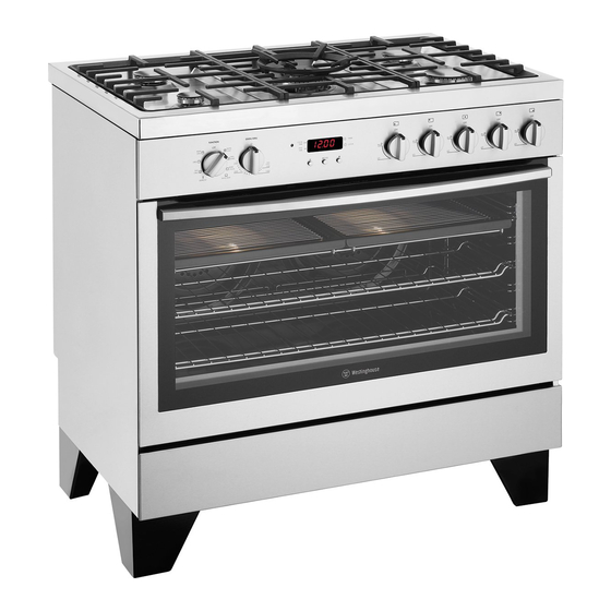
MODEL WFE912SA Gas hob, multi-function electric oven with electronic timer Removable wok trivet Stainless steel splashback (optional to fit) Removable cast iron trivet Gas burner Control panel Oven door Control Panel COOK BAKE Oven function selector Clock/Timer display Oven temperature control Gas hob burner controls Medium heat burner Gas Hob Low heat burner High heat burner Intense heat wok burner DESCRIPTION... -
Page 6: Wfe914Sa
MODEL WFE914SA Gas hob with flame safeguard, multi-function electric oven with touch control timer Removable wok trivet Stainless steel splashback (optional to fit) Removable cast iron trivet Gas burner 1 2 :0 0 Control panel Oven door Storage compartment Stainless steel kick panel Control Panel BAKE Oven function selector Clock/Timer display Oven temperature control Gas hob burner controls Medium heat burner Gas Hob Low heat burner High heat burner Intense heat wok burner DESCRIPTION... -
Page 7: Wfe916Sa
MODEL WFE916SA Gas hob with flame safeguard, programmable touch control electric oven Removable wok trivet Stainless steel splashback (optional to fit) Removable cast iron trivet Gas burner Control panel Oven door Storage compartment Stainless steel kick panel Control Panel ON/OFF FUNCTION FAST HEAT UP Programmable controller Gas hob burner controls Medium heat burner Gas Hob High heat burner Low heat burner Intense heat wok burner DESCRIPTION... -
Page 8: Wfe946Sa
MODEL WFE946SA Touch control electric ceramic hob, programmable touch control electric oven Stainless steel splashback Hob element controls Ceramic glass hob Oven control panel Oven door Storage compartment Stainless steel kick panel Ceramic hob touch controls Control Panel - oven programmable controller ON/OFF FUNCTION FAST HEAT UP Programmable controller Triple ring cooking zone Ceramic Hob Multi-purpose double cooking zone Small cooking zone Medium cooking zone Small cooking zone DESCRIPTION... -
Page 9: Wve916Sa
MODEL WVE916SA Programmable touch control electric oven Control Panel - oven programmable controller ON/OFF FUNCTION FAST HEAT UP Programmable controller DESCRIPTION... -
Page 10: Before Operating Your Appliance For The First Time
BEFORE OPERATING YOUR APPLIANCE FOR THE FIRST TIME PROGRAMMABLE CONTROLLER: MODELS WFE916, WFE946 & WVE916 TIPS & INFORMATION • A fter the appliance has been electrically connected, the set clock symbol will flash on the clock display. SETTING THE TIME • T o set the time of day, press – or +. 5 seconds after If you have purchased a model fitted with an electronic or the last change the timer arrow will disappear, programmable timer, you MUST set the time of day before confirming the time has been set. Once the time has you can operate your appliance. been entered, the clock advances minute by minute. NOTE: The clock has a 24-hour display. PUSH BUTTON AND TOUCH CONTROL ELECTRONIC CLOCK MODELS WFE912 &... -
Page 11: Installing Your Oven Accessories
INSTALLING YOUR OVEN ACCESSORIES PRIOR TO INSTALLING ACCESSORIES, REMOVE ALL PACKAGING SIDE RACKS AND REMOVE PLASTIC FILM FROM EXTERNAL PANELS The side racks that come with your oven are fitted in the following manner • Insert the 2 rear pegs into the holes provided • L ocate the front peg into the front access hole and push in firmly. CATALYTIC LINERS (ON SELECTED MODELS) Catalytic liners are coated with a specially formulated enamel coating. This porous coating enables the “self cleaning” process – see Cleaning your appliance section for more details. Catalytic liners must be installed first but you can omit them, if you wish, with no effect to cooking performance. - Page 12 INSTALLING BURNERS AND TRIVETS INSTALLING YOUR OVEN ACCESSORIES SHELVES AND TRAYS INSTALLING BURNERS The shelves are designed so that they have maximum travel • T he burner crown must be fitted correctly into the burner but cannot be accidentally pulled right out. The trays are cup or damage will occur during operation. designed in the same way and fit straight into the side racks. • T o do this, ensure that the 2 ribs on either side of the • L ocate the rear edge of the shelf/tray in between 2 spark plug hole are positioned into the 2 slots on the guide rails of the side rack – see diagram. Ensure the burner cup. same rail positions on both sides of the oven are • T he burner cap is simply positioned over the top of the being engaged. burner crown. • W ith the front edge raised, begin to slide the shelf into the oven.
-
Page 13: Getting To Know Your Cooktop
GETTING TO KNOW YOUR GAS COOKTOP USING YOUR GAS HOTPLATES MODEL WFE912 & WFE914 NOTE: Gas controls turn anticlockwise from ‘Off’ and have limited movement. LIGHTING BURNERS Electronic ignition These hobs are fitted with mains powered electronic ignition. When the appliance has been connected and the power is on, depressing any knob will release sparks MODEL WFE916 to all burners. To light a burner, depress the corresponding knob and while continuing to depress knob turn anticlockwise to ‘HI’ position. The knob may be released once the flame is established, and turned further anticlockwise to reduce the flame height as desired. Flame safeguard models WFE914 & WFE916 Models with flame safeguard have the same ignition procedure as electronic ignition, but require the knob to continue to be depressed after flame is established for... - Page 14 GETTING TO KNOW YOUR CERAMIC COOKTOP CERAMIC HOTPLATES MODEL WFE946 WARNING The cooktop is made from ceramic glass, a tough, durable material that withstands heating and cooling without If the ceramic glass is cracked, switch off the appliance to breaking. It is strong enough to hold the heaviest utensils. avoid the possibility of electric shock. However, it must be remembered that as it is GLASS, it may break. Treat it accordingly! The heating elements are concealed under the smooth glass surface which has a pattern to show the location of the Should you have any questions about the glass in your new elements. appliance, please contact the service centre by dialling 1300 363 640. • U se pans with smooth, clean and dry bottoms to avoid scratching or burning residue into the glass. • E nsure the pan bottom is the same size as the working element. • W e do not recommend ceramic glass pans because they do not conduct heat well. • Stainless steel or enamelled saucepans are best. • D o not use pans with copper or aluminium bottoms because they can leave traces which are difficult to remove from the glass.
- Page 15 GETTING TO KNOW YOUR CERAMIC COOKTOP CERAMIC COOKTOP CONTROLS ON/OFF WITH POWER INDICATOR DISPLAYS LOCK WITH PILOT LIGHT TRIPLE RING COOKING ZONE ICONS DISPLAY DESCRIPTION DISPLAY Cooking zone is switched off ZONE INDICATOR HEAT SETTING SELECTION Keep warm Keep warm setting is set TIMER SETTING SELECTION settings TIMER DISPLAY Heat settings Heat setting is set MULTIPURPOSE COOKING ZONE...
-
Page 16: Using Your Ceramic Cooktop
USING YOUR CERAMIC COOKTOP SWITCHING THE CERAMIC COOKTOP ON AND OFF LOCKING/UNLOCKING THE CONTROL PANEL The control panel, with the exception of the ‘On/Off’ sensor field, can be locked at any time in order to prevent the CONTROL PANEL DISPLAY settings being changed eg. By wiping over the panel with Switch on Touch for 2 seconds a cloth. Switch off Touch for 2 seconds / none CONTROL PANEL DISPLAY Switch on Touch (for 5 seconds) TIPS & INFORMATION Switch off the previously set heat settings Touch After switching on, within approx. 10 seconds a heat setting... - Page 17 USING YOUR CERAMIC COOKTOP The length of time that the automatic warm up function OVERRIDING THE CHILD SAFETY DEVICE operates depends on the heat setting selected. The child safety device can be switched off in this way for a single cooking session; it remains activated afterwards. HEAT SETTING AUTOMATIC WARM UP (MIN:SEC) STEP CONTROL PANEL DISPLAY 0.30 Switch the appliance on 1.00 Touch for 4 seconds lights up 1.40 Until the appliance is next switched off, it can be used as normal. After switching off the appliance, the child safety 4.50 device is active again 6.30 10.10 TIPS & INFORMATION 2.00 After overriding the child safety device, a heat setting or a function must be set within approx. 10 seconds, otherwise 3.30...
- Page 18 USING YOUR CERAMIC COOKTOP USING THE TIMER SETTING THE TIME OUTCOME AFTER THE STEP CONTROL PANEL DISPLAY FUNCTION CONDITION TIME HAS LAPSED Select cooking Pilot light for the cooking zone Automatic a heat setting is set acoustic signal selected flashes zone cut-out flashes Cooking to minutes Touch or zone switches off After a few seconds the pilot light flashes more slowly Countdown cooking zones not acoustic signal The time is set timer...
- Page 19 USING YOUR CERAMIC COOKTOP AUTOMATIC SWITCH OFF Cooking surface • I f after switching on the cooking surface, a heat setting is not set for a cooking zone within approx. 10 seconds, the cooking surface automatically switches itself off. • I f one or more sensor fields are covered by objects (a pan, cloths, etc.) for longer than approx.10 seconds, a signal sounds and the cooking surface switches off automatically. • I f all cooking zones are switched off, the cooking surface automatically switches itself off after approx. 10 seconds. Control panel • W hen the appliance is switched off, if one or more of the sensor fields on the control panel are covered for more than 10 seconds, an acoustic signal sounds. The acoustic signal switches itself off automatically when the sensor fields are no longer covered. Cooking zones If one of the cooking zones is not switched off after a certain time, or if the heat setting is not modified, the relevant cooking zone switches off automatically and...
-
Page 20: Using Your Oven
USING YOUR OVEN UNDERSTANDING YOUR OVEN FUNCTIONS BASE HEAT The following lists the oven functions available with the programmable controller (models WFE916, WFE946 & WVE916). Multifunction models (WFE914 & WFE912) have all oven functions except for Fan Assist, Pizza and Fast Heat Up. Function 4 RAPID HEAT Heat comes from the element below the floor of the oven. The Element is controlled by the thermostat and will turn on and off to maintain the set temperature. The “Base Heat” function can be used to add extra browning to the bases of pizzas, pies and pastries. Cook in the lower half of the Function 1 oven when you are using only one shelf. For best results, use silver or shiny trays. Heat comes from the elements surrounding the fans as well as the smaller element above the food. This allows you to FAN ASSIST preheat your oven 30% quicker than on standard “Bake”. “Rapid Heat” is ideal for cooking frozen pre-cooked foods such as savoury dishes, pastries, pizzas, mini meals (TV dinners), meat pies and fruit pies. Simply place the food in the oven straight from the freezer and heat – ideal for busy people. Cook in the upper half of the oven for best results. Function 5 FAN BAKE Heat comes from two elements, one above and one below the food. The fans circulate the hot air around the oven cavity so that you can put the food in different places... - Page 21 USING YOUR OVEN DEFROST MAXI GRILL Function 10 Function 7 “Maxi Grill” directs radiant heat from 2 powerful upper The “Defrost” function uses low temperature air that is elements onto the food. You can use the “Maxi Grill” circulated by the fans. You can defrost (thaw) your food function for tender cuts of meat, steak, chops, sausages, before you cook it. You can also use “Defrost” to raise fish, cheese toasties and other quick cooking foods. your yeast dough and to dry fruit, vegetables and herbs. Grill with the oven door closed. “Maxi Grill” allows you to take full advantage of the large FAN GRILL grill dish area and will cook faster than normal “Grill”. For best results it is recommended to preheat your grill for 3 minutes. This will help seal in the natural juices of steak, chops etc. for a better flavour. You can slide your grill dish into either of the 2 spaces within the upper pairs of support rails. Function 8 FAST HEAT UP “Fan Grill” offers you the benefits of both “Bake” and traditional “Grill” functions. The grill element turns on and off to maintain the set temperature while the fans circulate the heated air. The oven door remains closed for fan grill. You can use “Fan Grill” for large cuts of meat to give you a result that is similar to “rotisserie” cooked meat. Put your food on a shelf in the second lowest shelf “Fast Heat Up” can be selected in the initial heat up position. Put the grill dish on the lowest shelf position to phase of any cooking function. During “Fast Heat Up”...
- Page 22 USING YOUR OVEN OPERATING THE PUSH BUTTON & TOUCH CONTROL CLOCK OPERATING YOUR OVEN TEMPERATURE AND FUNCTION SELECTORS MODELS WFE912 & WFE914 ONLY MODELS WFE912 & WFE914 To set the oven, turn the function selector to the desired cooking function and then turn the temperature selector Oven to the desired temperature. An indicator light above the indicator temperature selector will come on. When the temperature is reached the heating source switches itself off and the indicator light goes out. When the oven temperature falls below the desired setting, the heating source switches on and the indicator light comes on again. MODEL WFE912 Once the food is cooked, turn the temperature selector off in an anticlockwise direction. Do not force it right round in a clockwise direction as this will result in damage to the Oven...
- Page 23 USING YOUR OVEN SETTING THE COOKING DURATION TO CHECK OR CANCEL SETTINGS 1. C heck the clock displays the correct time of day. 1. T o check your settings, press “mode” until the setting 2. S elect the desired oven function and temperature. you want is displayed. A red light will flash next to the The oven indicator light will glow and the heating mode (cook time, end time etc) that is currently on source will come on. display. 3. P ress “mode“ until the “cook time” indicator I 2. T o cancel “delayed start” press “mode” until a light begins flashing. flashes next to “cook time”. Press and hold “–” until the clock no longer reverses (“0:00” and you will hear 4. S et the cooking duration you want by using – or +.
- Page 24 USING YOUR OVEN USING YOUR PROGRAMMABLE CONTROLLER TO OPERATE THE OVEN MODELS WFE946 & WVE916 ON/OFF FUNCTION FAST HEAT UP Programmable controller MODEL WFE916 ON/OFF FUNCTION FAST HEAT UP Programmable controller Gas hob burner controls SETTING THE TIME OF DAY SETTING THE COOKING TIME After the appliance has been electrically connected the 1. S elect the desired oven function and cooking “set clock” symbol will flash on the clock display.
- Page 25 USING YOUR OVEN ON COMPLETION OF COOKING BEEP ON TOUCH When the set time has elapsed, a signal will sound for The beep sound can be activated anytime when a symbol 1 minute, the oven will switch off and the remaining time is pressed. indication “0.00” will appear on the display. 1. E nsure the oven is off by pressing “On / Off”. 1. To stop the signal, press “+” or “–”. 2. P ress “Function” and + simultaneously for 2 seconds, a single beep will sound to confirm the operation. Repeat the above procedure to reset the beep on touch SETTING THE MINUTE MINDER For setting a countdown period. When the period of time mode. As default, the beep on touch mode is off. has elapsed, an audible signal is sounded. SAFETY CUT-OUT FEATURE NOTE: This feature has no effect on the oven operation. The oven automatically switches itself off if the temperature 1. P ress “Timer” as often as necessary, until the “minute is not adjusted or the appliance is left operating after a...
-
Page 26: Cooking Test
COOKING TEST GET TO KNOW YOUR NEW OVEN WITH THIS ‘SIMPLE TEST CAKE’ METHOD: Although we strive for a perfect performing oven, it’s 1. B utter base and sides of two, 20cm straight-sided possible that there will be some variation in colour when round or square cake pans. Then line the base with baking. Therefore, we suggest this simple, easy and grease proof or baking paper. delicious to make Simple Test Cake, it can help you 2. P reheat oven to moderate ‘180ºC’ (170ºC fan understand your new oven. All ovens do sometimes have forced) and ensure oven shelf is in the centre position hot or cold spots, therefore it is important to judge with of oven. your eye as you may require to rotate during baking. 3. C ream softened butter and sugar until light in colour. 4. A dd vanilla essence. 5. T hen eggs one at a time, beating well after each ‘SIMPLE TEST CAKE’... -
Page 27: Cooking Guide
COOKING GUIDE • F or best baking results preheat oven for 30 minutes • S elect the correct shelf location for food being cooked. • T he grill tray can be used in the oven as a baking dish, except in oven shelf location 1. • M ake sure dishes will fit into the oven before you switch it on. • K eep edges of baking dishes at least 40mm from the side of the oven. This allows free circulation of heat and ensures even cooking. • D o not open the oven door more than necessary. • D o not place foods with a lot of liquid into the oven with other foods. This will cause food to steam and not brown. • A fter the oven is turned off it retains the heat for some time. Use this heat to finish custards or to dry bread. - Page 28 COOKING GUIDE CHOOSING THE BEST OVEN SETTINGS The following table is intended as a guide and experience may show some variation in cooking times necessary to meet individual requirements. We recommend that you preheat your oven for 30 minutes. MODES WITHOUT OVEN FAN FOOD TEMPERATURE C OVEN SHELF POSITION* TIME IN MINUTES Scones Plain or fruit 3 or 4 10 – 15 Biscuits Rolled 13 – 18 Spooned 13 – 18 Shortbread biscuits 30 – 35 Meringues Hard – individual Soft – individual 15 – 20 Pavlova – 6 egg Cakes Cup cakes 3 or 4 15 – 20 Sponge – 4 egg...
- Page 29 COOKING GUIDE ROASTING MEAT GRILLING GUIDE 1. P lace the meat in the oven and set the temperature between 180°C and 200°C. (It is recommended to WARNING wrap your meats in an oven roasting bag or foil to NOTE: Always clean the grill/oven dish after every use. prevent fats and oils from splattering, making it easier Excessive fat build up may cause a fire. to clean your oven.) 2. U se the grill/oven dish and grill insert. GRILLING IS CONDUCTED WITH THE OVEN DOOR CLOSED Place the meat on the insert.
-
Page 30: Dealing With Cooking Problems
DEALING WITH COOKING PROBLEMS (SEE ALSO SOLVING PROBLEMS) PROBLEM CAUSES REMEDIES Uneven cooking: • I ncorrect shelf position. – S elect shelf that puts food in the centre of the oven. • O ven tray too large. – E xperiment with other trays or dishes. • T rays not centralised. – C entre trays. • A ir flow in oven uneven. – R otate food during cooking. • G rill dish affecting thermostat. – R emove grill dish from oven on bake modes. Baked products too brown • O ven not preheated. -
Page 31: Cleaning Your Appliance
CLEANING YOUR APPLIANCE GAS HOTPLATE WARNING • T he trivets can be removed for cleaning by carefully lifting them from the hob. • A lways make sure that the oven is electrically isolated • Clean by washing with warm soapy water. before cleaning. This can be done by the functional • T he burner caps and crowns are also removable for switch nearby cleaning. • D o not line the bottom of the oven with foil or cookware • I f the caps, crowns and cups are heavily soiled, use a • Do not use steam cleaners non-abrasive cleaning compound. STAINLESS STEEL • F lame port blockages should be removed by using a matchstick or brush. -
Page 32: Cleaning Oven Accessories
CLEANING YOUR OVEN ACCESSORIES REMOVING THE TRAYS AND SHELVES FROM YOUR APPLIANCE CLEANING YOUR OVEN DOOR • S lide the dish and grill tray towards you until they The oven door has been designed to allow the two inner reach the front stop. door glasses to be removed for cleaning without removing • T ilt them up at the front to clear the side supports, the door from the product. taking care not to spill the contents. Removing the inner door glass for cleaning: • L ift them clear. • Open the door fully to gain access to the hinges • W ash the tray and shelves in hot soapy water. • P ush down the hinge locking tab as shown in the • R everse the above steps to put the grill tray and diagram on both sides of door... - Page 33 CLEANING YOUR OVEN ACCESSORIES CLEANING YOUR OVEN DOOR CHANGING THE LIGHT GLOBE • T here are 2 light globes located in the top of the oven WARNING cavity towards the front. The light globe glass is accessible • D O NOT use the oven without the inner and middle between the passes of the upper element. door glass fitted. • To remove, turn oven light glass anticlockwise. • N EVER spray any caustic cleaners on any surface of the • A special high temperature resistant globe should be used. door or damage to the surface coatings will result. This can be purchased from the customer care centre. • D O NOT use metal utensils, scrapers, scourers, or abrasive cleaners to clean the glass or any of the door trims. These will damage or scratch the surface coatings and degrade the finish and appearance.
-
Page 34: Catalytic Liners
CATALYTIC LINERS STORAGE COMPARTMENT (SELECTED MODELS) (WHERE FITTED) The storage compartment is accessible through the pivoting door. OPERATION Unused oven racks and grill dishes can be stored here. The catalytic liners are coated with a specially formulated enamel coating, over a base of regular enamel. This enamel coating has a rough surface which is also porous. WARNING During normal cooking, fats and other food spatter is DO NOT store flammable or combustible items in the storage partially absorbed into the surface and then oxidised compartments. This is not a compartment for warming food. away. This oxidisation of the fat works best if the oven is set at high temperatures. If you do a lot of lower temperature baking, say around the normal 180ºC, then the cleaning process may not be complete. Every now and then you should turn the oven on to 260ºC for around one hour to completely remove the soil. DO NOT place catalytic liners in the dishwasher. CLEANING Should the panels become heavily soiled, they will need to be taken out of the oven and cleaned by hand. They should be soaked in warm, soapy water for at least 2 hours and then wiped clean with a soft cloth. WARNING • S olid cleaning powders, creamy cleansers, caustic oven cleaners, steel wool or other scourers will ruin the catalytic surface and must NEVER BE USED. • W hen running the oven at 260°C to clean the catalytic liners, surfaces under these conditions will be hotter than usual and children should be kept away. -
Page 35: Solving Problems
SOLVING PROBLEMS FAULTS FURTHER INFORMATION If there is a problem with the oven and/or grill, please: When you need information, service or replacement parts or have a warranty enquiry, please contact the Customer Care Centre: • C heck the points listed below before calling for service. It may be possible to avoid a call by fixing • A ustralia - 1300 363 640, 8.00am - 5.00pm the problem yourself – and so continue cooking. EST Monday to Friday • N ew Zealand - 09 573 2384, 8.00am - 5.00pm NOTE: We may charge for service even in the guarantee EST Monday to Friday period if your problem is due to the causes listed below. P lease have the following information ready: Model, Model Number & Serial Number. This is shown on the data plate which is visible when the oven door is open. -
Page 36: Installing Your Appliance
INSTALLATION OF THE APPLIANCE INSTALLING SPLASHBACK (MODELS WITH HOB ONLY) GAS MODEL CLEARANCE REQUIREMENTS MODELS WFE912, WFE914 &WFE916 • E nsure the appliance is installed in accordance with clauses 6.2.5 and 6.10.1.1 of AS/NZS 5601.1 or clauses 6.9.1 and 6.9.5 of AS/NZS 5601.2 with regard to clearances to combustible surfaces and materials, and clearances to rangehoods and exhaust fans, to ensure clearances of 200mm from burners to vertical combustible surfaces observe the minimum dimension of 100mm from each side of the cooker to Fit splashback to rear of hob with three screws provided. combustible surfaces. • C learances to combustible surfaces may be reduced CABINET REQUIREMENTS if combustible surfaces are protected in accordance Models WFE912, WFE914, WFE916, & WFE946 are with clause 6.10.1.2 of AS/NZS 5601.1, or clause designed to fit into a 900mm wide gap between standard 6.9.2 of AS/NZS 5601.2. - Page 37 INSTALLATION OF THE APPLIANCE FLOOR MOUNTED INSTALLATION The floor mounted type installation uses the appliance as supplied, and can be fitted in between cabinets, with cabinets on one side or without adjacent cabinets. There is no clearance requirement to adjacent side cabinets. To ensure cooker stability, the anti-tilt brackets must be installed, and the end of chain attached to the appliance must be placed onto hook attached to the rear wall. 90 0m m mi nim um 6 0 0 m m 900mm minimum 600mm 6 0 0 m m m in im u 600mm minimum 6 0 0 m m 600mm v e rt ic a l c le a ra vertical clearance...
- Page 38 INSTALLATION OF THE APPLIANCE FLOOR MOUNTED INSTALLATION (continued) INSTALLATION OF ANTI-TILT BRACKETS AND HOOK • T h e anti-tilt brackets must be secured to the floor at rear of cavity with an appropriate fastener according to dimensions in diagram Hole location for hook installation Measurements are to be adjusted to account for the thickness of any skirting Measurements are to be adjusted to account for board or tiles coming between the back of the appliance and the wall. the thickness of any skirting board or tiles coming between the back of the appliance and the wall Hook...
- Page 39 INSTALLATION OF THE APPLIANCE SLOT-IN INSTALLATION SLOT IN CONVERSION To convert the appliance for slot in installation the kick panel provided on the appliance is removed and the appliance is mounted on a plinth. This enables a continuous cupboard kick board to be installed, giving a more integrated appearance. There is no clearance requirement between oven and adjacent side cabinets. 900 mm min imu m 6 0 0 m m 600mm 900mm minimum 6 0 0 m m m in im u 600mm minimum v e rt ic a l c le a ra vertical clearance n c e fr o m c o m b...
- Page 40 INSTALLATION OF THE APPLIANCE SLOT-IN INSTALLATION (continued) INSTALLATION OF ANTI-TILT BRACKETS AND STOPS • T he brackets are to be secured to the back wall with • O nce services are connected, product can be lifted appropriate fasteners. onto the plinth and pushed back carefully, ensuring the • T he bottom edge of the the brackets rest on the appliance engages into both brackets at the rear and horizontal support surface. the front stops. • T wo stops are to be screwed to the plinth in locations • I f the product requires removal for service, it must be as shown (stops provided). The stops locate into slots in lifted at the front approximately 5mm to clear the front the base of the appliance to prevent the product from stops prior to being pulled forward.
- Page 41 BUILT-IN INSTALLATION CABINET CONSTRUCTION FOR BUILT IN OVEN For the best integration within a kitchen, install this appliance in a cupboard that gives a flush fit with the surrounding cupboard fronts. A recess of 20mm is ideal. Alternatively, the oven can be proud mounted. See diagrams below for details. NOTE: Your appliance must be mounted on a flat surface for the full width and depth of the product. 900mm Flush mount option 864mm Cupboard door Infill panel Infill panel Cupboard door 900mm Proud mount option...
- Page 42 INSTALLATION OF THE APPLIANCE UNDERBENCH INSTALLATION VERTICAL CABINET INSTALLATION Your underbench oven looks best when the control panel The oven can be built into a vertical cabinet in the same is directly under the benchtop. An upper infill panel may manner as an underbench. The required cavity dimensions be added if the cooktop placed above the benchtop is are the same and the product is secured to the cabinet in too deep. *Refer to cooktop installation instructions for the same way. required clearance between cooktop and oven. Recess on 3 sides required for flush mount only * R efer cooktop installation requirements 876mm 580mm minimum flush mount Mounting holes 560mm minimum proud mount NOTE: The appliance must be fixed into position when installed by fitting 2 screws provided through mounting holes into cabinet.
- Page 43 WIRING REQUIREMENTS The cooker MUST be installed in compliance with: CONNECTING TO SERVICES AND COMMISSIONING • wiring connections in AS/NZS 3000 Wiring Rules This appliance must be installed by an authorised person, • l ocal regulations, municipal building codes and other according to all codes and regulations of: statutory regulations • Electrical supply authorities. • Building regulations For New Zealand Only: • Local government and council authorities. The cooking range must be connected to the supply by • A S/NZS5601.1(particular attention to 6.10.1 and a supply cord fitted with the appropriately rated plug figure 6.3, and clause 6.10.1.11). that is compatible with the socket-outlet fitted to the final • A S/NZS 3000 (particular attention to clause 4.3.11 sub-circuit in the fixed wiring that is intended to supply and clause 3.9).
- Page 44 ELECTRICAL & GAS CONNECTION LOCATIONS MODELS WFE912, WFE914, WFE916 AND WFE946 CHECKING PIPING SIZE To work out a suitable pipe size for connection use: Gas connection point to regulator The information in this table Models: WFE912, WFE914, WFE916 GAS TYPE NATURAL GAS UNIVERSAL LPG WFE912 & WFE914 49.6 MJ/h 40.9 MJ/h Electrical cable WFE916 58.6 MJ/h 47.4 MJ/h entry point Models: Information about the length of run, number of elbows, WFE912, WFE914, tees and bends, the available service pressure and the WFE916, WFE946 supply requirements. NOTE: AS/NZS5601.1 will help you with this matter. GAS CONNECTION Read these points before connecting to the gas supply: • T he appliance is preset for natural gas use, if LPG is...
- Page 45 LPG CONVERSION MODELS WFE912, WFE914 & WFE916 This appliance is supplied set up to for Natural Gas 9. O ne by one, turn the knobs to minimum and screw usage. A conversion kit is included with the product in the bypass screw (accessible when the knob is for Universal LPG usage. The conversion kit contains 6 removed) until a small stable flame results. Turn the injectors and 1 LPG sticker. knob to maximum and then back to minimum to ensure that the correct minimum flame is maintained. Please follow the procedure below if a conversion to suit UNIVERSAL LPG is required. 10. A ttach the LPG sticker to the cooker, near the gas supply inlet. Cover the Natural Gas label that is 1. R emove the hotplate trivets, burner caps and burner factory fitted. crowns to access the hotplate injectors. Replace the factory fitted injectors with the appropriate injectors, as Hex nut assembly, supplied. Refer to injector orifice table for injector sizes. fully screwed down The injector size is stamped on the side of the injector. 2. U nscrew the hex nut from the regulator. The hex nut, brass washer and nylon insert will disengage as an assembly.
- Page 46 TESTING THE OPERATION OF THE GAS COOKER NOTE: You MUST test the cooker after installation, before TESTING THE COOKER FEATURES you hand it over to the customer. You MUST have a • O bserve the flame appearance on each burner. If it is manometer and a connecting tube. much smaller or larger than expected, then the injector size needs checking.
-
Page 47: Warranty
Warranty FOR SALES IN AUSTRALIA AND NEW ZEALAND APPLIANCE: BUILT-IN OVEN, COOKTOP AND UPRIGHT RANGE COOKER This document sets out the terms and conditions of the product 6. Proof of purchase is required before you can make a claim under warranties for Electrolux Appliances. - Page 48 1800 350 067 email: customercare@electrolux.com.au web: www.westinghouse.com.au NEW ZEALAND phone: 09 573 2384 fax: 0800 363 600 email: customercare@electrolux.co.nz web: www.westinghouse.co.nz TOP SERVICE Top Service encompasses the after sales service provided by The Electrolux Group to consumers including delivery, home service and spare parts. Westinghouse. We are part of the Electrolux family. Share more of our thinking at www.electrolux.com Part Number: 0342 001 563 Issue C © 2012 Electrolux Home Products Pty Ltd ABN 51 004 762 341 WMAN_90cmOVEN_Oct12...
Need help?
Do you have a question about the WFE912SA and is the answer not in the manual?
Questions and answers