Table of Contents
Advertisement
Quick Links
Advertisement
Table of Contents

Related Manuals for IMC Networks iMcV-DS3


Summary of Contents for IMC Networks iMcV-DS3
- Page 1 Operation Manual...
-
Page 2: Fcc Radio Frequency Interference Statement
(6) years after the original date of purchase. This warranty is subject to the limitations set forth below. At its option, IMC Networks will repair or replace at no charge the product which proves to be defective within such warranty period. -
Page 3: Table Of Contents
Table of Contents FCC Radio Frequency Interference Statement ............ii Warranty......................ii About the iMcV-DS3/E3/STS-1 ................1 Configuration ....................1 DIP Switches..................... 2 Feature Descriptions ..................3 Installation ......................6 LEDs ......................... 7 Loopback Testing ....................8 Pseudorandom Bit Sequence (PRBS) Testing............9 Installation Troubleshooting................ - Page 4 Notes...
-
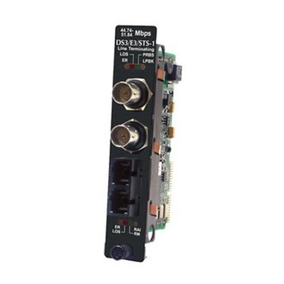
Page 5: About The Imcv-Ds3/E3/Sts-1
BNC/SSFX modules allow two wavelengths (1310 nm and 1550 nm) to share one fiber strand essentially doubling the capacity of installed fiber. You must deploy iMcV-DS3/E3/STS-1 modules in pairs (one at each end of a conversion). The data transmitted on the fiber ports can only be received and interpreted by the receive fiber of another iMcV-DS3/E3/STS-1. -
Page 6: Dip Switches
DIP switch settings can be overridden from software. DIP Switches The iMcV-DS3/E3/STS-1 DIP switches are located on S1 and S2 on the PCB. The S2 DIP switches are factory configured and must not be moved. The S1 DIP switches provide control over the available iMcV-DS3/E3/STS-1 features. -
Page 7: Feature Descriptions
Remote Management Disabled (D) S1-10: ON Remote Management Enabled Feature Descriptions The iMcV-DS3/E3/STS-1 module includes several features that allow it to be configured for varying DS3/E3/STS-1-based environments. Loopback This switch enables or disables the loopback feature. When this feature is enabled, the data line (Coax or Fiber) set by the Loopback Type DIP switch is looped back. - Page 8 The FiberAlert feature uses the iMcV-DS3/E3/STS-1 module LEDs to indicate that a loss of one strand of fiber has occurred. When a strand becomes unavailable, the iMcV-DS3/E3/STS-1 module at the receiver-end detects the loss of the link. The module then responds by stopping the transmission of the data and link signal until a new signal or link pulse is received on the strand.
- Page 9 ) when the iMcV-DS3/E3/STS-1 module is installed in a managed chassis. Transmit Data Source These switches select the transmit mode used by the iMcV-DS3/E3/STS-1 module. The transmit modes that can be selected include the following: • Standard data • Unframed All Ones (diagnostic) •...
-
Page 10: Installation
Save any blanks removed during installation for future use. NOTE It is not recommended that the iMcV-DS3/E3/STS-1 module be installed in an IE- MediaChassis/DC. The power source in this chassis is not isolated, and cannot support positive reference ground systems typically used in Telco environments. -
Page 11: Leds
LEDs The iMcV-DS3/E3/STS-1 module features several diagnostic LEDs per port. The LED functions are as follows: LEDs Next to Coax (BNC) Port • LPBK Glows green when module is in a Loopback mode. • NO LNK Glows green when a link is NOT established. -
Page 12: Loopback Testing
Looping received data back onto the transmit path helps determine whether a connection is still valid. Remote loopback tests isolate problems on the coax run between an iMcV-DS3/E3/STS-1 module and the connected device, while local loopback tests can isolate problems on the fiber... -
Page 13: Pseudorandom Bit Sequence (Prbs) Testing
Pseudorandom Bit Sequence (PRBS) Testing To test using Pseudorandom Bit Sequence, configure the iMcV-DS3/E3/STS-1 modules for No Loopback, then configure the Transmit Data Source to “Transmit Pseudorandom Bit Sequence.” Configure the local device for loopback, conduct the test, then check the PBEO LED to verify errors were not received (Refer to the LED section for more information). -
Page 14: Installation Troubleshooting
Installation Troubleshooting General Troubleshooting • During installation, first test your fiber and BNC connections with all troubleshooting features disabled, then enable these features, if desired, just before final installation. This will reduce the features’ interference with testing. • When working with units where the features cannot be disabled, you must establish BOTH your BNC and fiber connections;... -
Page 15: General Information
General Information IMC Networks Technical Support Tel: (949) 465-3000 or (800) 624-1070 (in the U.S. and Canada); +32-16-550880 (Europe) Fax: (949) 465-3020 E-Mail: techsupport@imcnetworks.com Web: www.imcnetworks.com Specifications Power Consumption (Typical): 0.550 Amps @ 5 V Operating Temperature: 32° to 122° F (0° to 50° C) Storage Temperature: 0°... -
Page 16: Safety Certifications
Directive on Electrical Equipment Designed for use within Certain Voltage Limits (73/23/EEC). Certified to Safety of Information Technology Equipment, Including Electrical Business Equipment. For further details, contact IMC Networks. Class 1 Laser product, Luokan 1 Laserlaite, Laser Klasse 1, Appareil A’Laser de Classe 1... - Page 17 Notes...
- Page 18 Notes...
- Page 19 Notes...
- Page 20 The information in this document is subject to change without notice. IMC Networks assumes no responsibility for any errors that may appear in this document. iMcV-DS3/E3/STS-1 is a trademark of IMC Networks. Other brands or product names may be trademarks and are the property of their respective companies.
Need help?
Do you have a question about the iMcV-DS3 and is the answer not in the manual?
Questions and answers