Table of Contents
Advertisement
Quick Links
Advertisement
Table of Contents

Related Manuals for IMC Networks iMcV-LIM


Summary of Contents for IMC Networks iMcV-LIM
- Page 1 Operation Manual...
-
Page 2: Fcc Radio Frequency Interference Statement
At its option, IMC Networks will repair or replace at no charge the product which proves to be defective within such warranty period. This limited warranty shall not apply if the IMC Networks product has been damaged by unreasonable use, accident, negligence, service or modification by anyone other than an authorized IMC Networks Service Technician or by any other causes unrelated to defective materials or workmanship. -
Page 3: Table Of Contents
Installing an iMcV-LIM ..................1 FX LinkLoss, TX LinkLoss, Link Fault Pass-Through, Far End Fault and FiberAlert.4 Link Fault Pass-Through (LFPT)................5 Using Far End Fault, and FiberAlert ..............5 Auto Negotiation on iMcV-LIM ................7 LED Operation....................8 Installation Troubleshooting ................9 Specifications ....................10 IMC Networks Technical Support..............10 Fiber Optic Cleaning Guidelines...............11... -
Page 4: About The Imcv-Lim
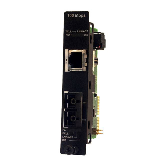
The iMcV-LIM is a Fast Ethernet module which provides a single conversion between 100Base-TX twisted pair and 100Base-FX/SX single-mode or multi-mode fiber. Each iMcV-LIM includes one RJ-45 connector and one pair of ST or SC fiber optic connectors Also available in a single-strand fiber version, iMcV-LIM TX/SSFX allows two wavelengths to share one fiber strand —... -
Page 5: Managed Modules
Managed Modules To manage one or more iMcV-LIM(s), an SNMP agent must be present in the chassis. To configure Managed Modules, install the module first, and then configure using the management software. All Fiber Type information is now loaded into the NVRAM during manufacturing. - Page 6 Default Setting DIP Switch on S1 Feature Auto Negotiation (AN) Far End Fault (FEF) FX LinkLoss (FXLL) TX LinkLoss (TXLL) FiberAlert (FA) Factory Default Factory Default Factory Default BEST PRACTICES When possible, it is always a good idea to configure DIP Switches to match software settings.
-
Page 7: Fx Linkloss, Tx Linkloss, Link Fault Pass-Through, Far End Fault And Fiberalert
The appropriate “LNK” (link) LED is lit to indicate this. The IMC Networks media converter also sends out link pulses from its copper and fiber transmitters, but normally has no way of knowing whether the cable to the other device is intact and the link pulses are reaching the other end. -
Page 8: Link Fault Pass-Through (Lfpt)
Link Fault Pass-Through (LFPT) is a troubleshooting feature that combines TX and FX LinkLoss from both the local and remote iMcV-LIM modules. LFPT is enabled by turning on both FX and TX LinkLoss on both modules. This feature allows either end of the conversion to detect a link fault occurring at the other end of the media conversion chain. - Page 9 For example if a fault should occur on segment 2 in the direction of segment 1 to 3, FEF would be engaged on the iMcV-LIM between segment 2 and 3. This would then send a signal back to the iMcV-LIM between segment 1 and 2. If the iMcV-LIM between segment 1 and 2 is in a managed chassis, the chassis would send a trap that the port is down.
-
Page 10: Auto Negotiation On Imcv-Lim
Full-Duplex Auto Negotiation is ON Auto Negotiation is ON Configure Auto Negotiation on an iMcV-LIM by adjusting the DIP Switch setting (for unmanaged modules) or via the management software. Refer to the DIP Switch table for switch location and settings. -
Page 11: Led Operation
AutoCross Feature for Twisted Pair Connection All twisted pair ports on the iMcV-LIM includes AutoCross, a feature that automatically selects between a crossover workstation and a straight-through connection depending on the connected device. LED Operation Each iMcV-LIM module features diagnostic LEDs that provide information on features and ports. -
Page 12: Installation Troubleshooting
LEDs will light. • To test a iMcV-LIM by itself, first, have an appropriate fiber patch cable, then follow these steps to test: Connect the iMcV-LIM to the twisted pair device with a twisted pair cable. -
Page 13: Specifications
Storage Temperature 0° - 122° F (-20° - 70° C) Humidity: 5 - 95% (non-condensing) DC Input iMcV-LIM w/LFPT: 0.80 Amp @ 5V Fiber Optic Specifications For fiber optic specifications, please visit: http://www.imcnetworks.com/adocs/fcs.asp IMC Networks Technical Support Tel: (949) 465-3000 or (800) 624-1070 (in the U.S. and Canada);... -
Page 14: Fiber Optic Cleaning Guidelines
Dust caps are installed at IMC Networks to ensure factory-clean optical devices. These protective caps should not be removed until the moment of connecting the fiber cable to the device. Should it be necessary to disconnect the fiber device, reinstall the protective dust caps. -
Page 15: Safety Certifications
Safety Certifications CE: The products described herein comply with the Council Directive on Electromagnetic Compatibility (2004/108/EC). Class 1 Laser product, Luokan 1 Laserlaite, Laser Klasse 1, Appareil A’Laser de Classe 1 European Directive 2002/96/EC (WEEE) requires that any equipment that bears this symbol on product or packaging must not be disposed of with unsorted municipal waste. - Page 16 The information in this document is subject to change without notice. IMC Networks assumes no responsibility for any errors that may appear in this document. iMcV-LIM is a trademark of IMC Networks. Other brands or product names may be trademarks and are the property of their respective companies.
Need help?
Do you have a question about the iMcV-LIM and is the answer not in the manual?
Questions and answers