Table of Contents
Advertisement
Quick Links
Advertisement
Table of Contents

Related Manuals for IMC Networks iMcV-DS3/E3-LineTerm


Summary of Contents for IMC Networks iMcV-DS3/E3-LineTerm
- Page 1 Operation Manual...
-
Page 2: Fcc Radio Frequency Interference Statement
At its option, IMC Networks will repair or replace at no charge the product which proves to be defective within such warranty period. This limited warranty shall not apply if the IMC Networks product has been damaged by unreasonable use, accident, negligence, service or modification by anyone other than an authorized IMC Networks Service Technician or by any other causes unrelated to defective materials or workmanship. -
Page 3: Table Of Contents
Table of Contents FCC Radio Frequency Interference Statement ............ii Warranty......................ii About the iMcV-DS3/E3-LineTerm ..............1 Configuration .....................1 Prerequisites ......................1 Managed Modules .....................2 Unmanaged Modules..................2 DIP Switches......................2 DIP Switch Settings ....................3 Features ......................3 Installation ......................6 LED Operation....................6 Loopback Testing ....................7 Pseudorandom Bit Sequence (PRBS) Testing ............9 Installation Troubleshooting ................10... -
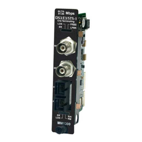
Page 4: About The Imcv-Ds3/E3-Lineterm
For example, one that transmits at 1310 nm must be paired with another that receives at 1310 nm. iMcV-DS3/E3-LineTerm modules must be deployed in pairs (one at each end of a fiber line). The data transmitted on the fiber ports can only be received and interpreted by another iMcV-DS3/E3-LineTerm unit. -
Page 5: Managed Modules
Managed Modules The iMcV-DS3/E3-LineTerm modules can be remotely managed when installed in a iMediaChassis™ with an SNMP management module. For a managed environment, first manually configure the desired features through DIP switch settings to ensure that they continue to function if management is ever lost. -
Page 6: Dip Switch Settings
S1-10: ON Remote Management Enabled Features The iMcV-DS3/E3-LineTerm module includes several features that allow it to be configured for DS3, E3, or STS-1-based environments. Loopback (DIP Switch S1, Position 1) This switch enables or disables the loopback feature. When this feature is enabled, the data line (Coax or Fiber) set by the “Loopback Type”... - Page 7 In this way, both upstream and downstream craft personnel are alerted to a single fault. The Fault Loopback feature uses the iMcV-DS3/E3-LineTerm module LEDs to indicate that a loss of one strand of fiber has occurred. When a strand becomes unavailable, the module at the receiver-end detects the “LOS”...
- Page 8 Transmit Coax Data Source (DIP Switch S1, Positions 6 & 7) These switches select the transmit mode used by the iMcV-DS3/E3-LineTerm module. The transmit modes that can be selected include the following: • Standard data • Unframed All Ones (diagnostic) •...
-
Page 9: Installation
NOTE It is not recommended that the iMcV-DS3/E3-LineTerm module be installed in an IE- MediaChassis/1-DC chassis. The power source in this chassis is not isolated and cannot support positive referenced ground systems typically used in Telco environments. -
Page 10: Loopback Testing
When the fiber port receives an RAI signal, this will force AIS to transmit on the COAX Line. Loopback Testing The iMcV-DS3/E3-LineTerm includes two loopback test modes: Coax Loopback and Fiber Loopback. The following illustrations show the path that a signal takes in each of the loopback test modes. - Page 11 Looping received data back onto the transmit path helps determine whether a connection is still valid. Remote loopback tests isolate problems on the coax run between an iMcV-DS3/E3-LineTerm module and the connected device, while local loopback tests can isolate problems on the fiber connected to the module.
-
Page 12: Pseudorandom Bit Sequence (Prbs) Testing
REMOTE iMcV-DS3/E3-LineTerm module. The fiber line returning from the remote iMcV-DS3/E3-LineTerm module is validated by verifying the RM LED is ON at the HOST iMcV-DS3/E3-LineTerm module. At this point all connections for the channel have been... -
Page 13: Installation Troubleshooting
Installation Troubleshooting General Troubleshooting • The Coax Port can easily be tested using the internal PRBS signal generator and detector and a physical wire loop on the coax interface. • The Fiber Port is internally tested at all times by a working pair of units. With one unit configured for Local Management (Switch 10 set OFF) and the other for Remote Management (Switch 1O set ON), the fiber line is verified if the “RM”... -
Page 14: General Information
General Information IMC Networks Technical Support Tel: (949) 465-3000 or (800) 624-1070 (in the U.S. and Canada); +32-16-550880 (Europe) Fax: (949) 465-3020 E-Mail: techsupport@imcnetworks.com Web: www.imcnetworks.com Specifications Standards Compliance (DS3, E3, STS-1): ANSI T1.102-1993 ANSI T1.107.1995 GR-820-CORE DS3, E3, STS-1 Interface: BNC coax 75 +/- 5% ohms DS3 (44.736 Mbps +/- 20 ppm) -
Page 15: Safety Certifications
Electrical Equipment Designed for use within Certain Voltage Limits (73/23/EEC). Certified to Safety of Information Technology Equipment, Including Electrical Business Equipment. For further details, contact IMC Networks. Class 1 Laser product, Luokan 1 Laserlaite, Laser Klasse 1, Appareil A’Laser de Classe 1... - Page 16 © 2008 IMC Networks. All rights reserved. The information in this document is subject to change without notice. IMC Networks assumes no responsibility for any errors that may appear in this document. iMcV-DS3/E3-LineTerm is a trademark of IMC Networks. Other brands or product names may be trademarks and are the property of their respective companies.
Need help?
Do you have a question about the iMcV-DS3/E3-LineTerm and is the answer not in the manual?
Questions and answers