Table of Contents
Advertisement
Quick Links
Advertisement
Table of Contents

Related Manuals for Crestron CEN-SW-POE-5


Summary of Contents for Crestron CEN-SW-POE-5
- Page 1 Crestron CEN-SW-POE-5 5-Port PoE Switch Installation Guide...
- Page 2 Laboratories, Inc. in the United States and/or other countries. Other trademarks, registered trademarks and trade names may be used in this document to refer to either the entities claiming the marks and names or their products. Crestron disclaims any proprietary interest in the marks and names of others. Crestron is not responsible for errors in typography or photography.
-
Page 3: Table Of Contents
Crestron CEN-SW-POE-5 5-Port PoE Switch Contents 5-Port PoE Switch: CEN-SW-POE-5 Introduction ..........................1 Features and Functions ....................1 Specifications ......................2 Physical Description....................3 Setup ............................9 Network Wiring......................9 Supplied Hardware ...................... 9 Installation ......................... 10 Hardware Hookup ..................... 12 Problem Solving ........................ -
Page 5: 5-Port Poe Switch: Cen-Sw-Poe-5
CAT5/CAT6 network cable. All five ports are gigabit capable to ensure maximum bandwidth for multimedia and critical control data. Using the CEN-SW-POE-5, there is no need to install a separate power supply at each networked device location. The CEN-SW-POE-5 can simply be mounted at a convenient location on a wall or in an equipment rack, providing a single power source for four separate 802.3af compliant... -
Page 6: Specifications
5-Port PoE Switch Crestron CEN-SW-POE-5 Specifications Specifications for the CEN-SW-POE-5 are listed in the following table. CEN-SW-POE-5 Specifications SPECIFICATION DETAILS Ethernet Ports (5) 10BASE-T/100BASE-TX/ 1000BASE-T Ethernet Network Standards IEEE 802.3, 802.3u, 802.3ab, 802.3x, and 802.3af Transmission Method Store-and-forward Power Requirements 48 Vdc @ 1.25 A,... -
Page 7: Physical Description
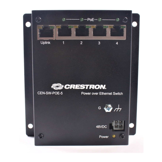
Crestron CEN-SW-POE-5 5-Port PoE Switch Physical Description This section provides information on the connections and indicators available on the CEN-SW-POE-5. CEN-SW-POE-5 Physical View 5-Port PoE Switch: CEN-SW-POE-5 3 Installation Guide – DOC. 7524A... - Page 8 5-Port PoE Switch Crestron CEN-SW-POE-5 CEN-SW-POE-5 Overall Dimensions Front View Bottom View 4 5-Port PoE Switch: CEN-SW-POE-5 Installation Guide – DOC. 7524A...
- Page 9 Crestron CEN-SW-POE-5 5-Port PoE Switch CEN-SW-POE-5 Connectors & Indicators 5-Port PoE Switch: CEN-SW-POE-5 5 Installation Guide – DOC. 7524A...
- Page 10 No Connection Data Pair 4 No Connection Data Pair 4 (4) Green LEDs, indicate that the corresponding PoE port is providing power to an 802.3af-compliant device (Continued on following page) 6 5-Port PoE Switch: CEN-SW-POE-5 Installation Guide – DOC. 7524A...
- Page 11 Data Pair 2 +Vdc Data Pair 3/+Vdc +Vdc Data Pair 3/+Vdc Data Pair 2 Data Pair 2 -Vdc Data Pair 4/-Vdc -Vdc Data Pair 4/-Vdc (Continued on following page) 5-Port PoE Switch: CEN-SW-POE-5 7 Installation Guide – DOC. 7524A...
- Page 12 48 Vdc power input (power pack included) 48VDC Connector Pin Assignments DESCRIPTION +48 Vdc +48 Vdc Ground Ground Power (1) Yellow LED, indicates operating power supplied from external power pack 8 5-Port PoE Switch: CEN-SW-POE-5 Installation Guide – DOC. 7524A...
-
Page 13: Setup
For information on connecting Ethernet devices in a Crestron system, refer to the latest version of the Crestron e-Control Reference Guide (Doc. 6052), which is available for download from the Crestron Web site (www.crestron.com/manuals). Supplied Hardware The hardware supplied with the CEN-SW-POE-5 is listed in the following table. -
Page 14: Installation
Rack The CEN-SW-POE-5 can be mounted to a front or rear rail of a rack Mounting using the supplied rack screws and washers. Either the left or right flange of the switch can be used to mount the unit to the rack. - Page 15 Crestron CEN-SW-POE-5 5-Port PoE Switch Wall The CEN-SW-POE-5 can be mounted to a wall. To mount the device to a Mounting wall, use the four supplied 3/16 x 1-1/4” pan head Phillips drywall screws (refer to the illustration below). Wall Mounting 5-Port PoE Switch: CEN-SW-POE-5 ...
-
Page 16: Hardware Hookup
Make the necessary connections as called out in the illustration that follows this paragraph. Apply power after all connections have been made. When making connections to the CEN-SW-POE-5, note the following: Use Crestron power supplies for Crestron equipment. The included cable(s) cannot be extended. -
Page 17: Problem Solving
Crestron CEN-SW-POE-5 5-Port PoE Switch Problem Solving Troubleshooting The following table provides corrective action for possible trouble situations. If further assistance is required, please contact a Crestron customer service representative. CEN-SW-POE-5 Troubleshooting TROUBLE POSSIBLE CAUSE(S) CORRECTIVE ACTION Power LED Power cord (ac) is not... - Page 18 PoE LED 10BASE-T/100BASE-TX/ PoE LED does not 1000BASE-T compatible illuminates only illuminate. device is not 802.3af when the compliant. associated port on the switch connects to an 802.3af-compliant device. 14 5-Port PoE Switch: CEN-SW-POE-5 Installation Guide – DOC. 7524A...
-
Page 19: Reference Documents
Crestron Web site (www.crestron.com/offices) for assistance within a particular geographic region. To post a question about Crestron products, log onto the Online Help section of the Crestron Web site (www.crestron.com/onlinehelp). First-time users must establish a user account to fully benefit from all available features. -
Page 20: Future Updates
5-Port PoE Switch Crestron CEN-SW-POE-5 Future Updates As Crestron improves functions, adds new features and extends the capabilities of the CEN-SW-POE-5, additional information may be made available as manual updates. These updates are solely electronic and serve as intermediary supplements prior to the release of a complete technical documentation revision. -
Page 21: Return And Warranty Policies
(property or economic damages inclusive) arising from the sale or use of this equipment. CRESTRON is not liable for any claim made by a third party or made by the purchaser for a third party. - Page 22 5-Port PoE Switch Crestron CEN-SW-POE-5 This page is intentionally left blank. 18 5-Port PoE Switch: CEN-SW-POE-5 Installation Guide – DOC. 7524A...
- Page 23 Crestron CEN-SW-POE-5 5-Port PoE Switch This page is intentionally left blank. 5-Port PoE Switch: CEN-SW-POE-5 19 Installation Guide – DOC. 7524A...
- Page 24 Crestron Electronics, Inc. Installation Guide – DOC. 7524A 15 Volvo Drive Rockleigh, NJ 07647 (2036362) Tel: 888.CRESTRON 03.13 Fax: 201.767.7576 Specifications subject to www.crestron.com change without notice.
Need help?
Do you have a question about the CEN-SW-POE-5 and is the answer not in the manual?
Questions and answers