Table of Contents
Advertisement
Quick Links
Advertisement
Table of Contents

Related Manuals for Crestron Crestron CEN-SW-POE-5


Summary of Contents for Crestron Crestron CEN-SW-POE-5
- Page 1 Crestron CEN-SW-POE-5 5-Port Power over Ethernet Switch Installation Guide...
- Page 2 This document was prepared and written by the Technical Documentation department at: Crestron Electronics, Inc. 15 Volvo Drive Rockleigh, NJ 07647 1-888-CRESTRON All brand names, product names and trademarks are the property of their respective owners. ©2008 Crestron Electronics, Inc.
-
Page 3: Table Of Contents
Crestron CEN-SW-POE-5 Contents 5-Port Power over Ethernet Switch: CEN-SW-POE-5 Introduction ... 1 Features and Functions ... 2 Specifications ... 3 Physical Description... 4 Industry Compliance ... 10 Setup ... 11 Network Wiring... 11 Supplied Hardware ... 11 Installation ... 12 Hardware Hookup ... -
Page 5: 5-Port Power Over Ethernet Switch: Cen-Sw-Poe-5
5-Port Power over Ethernet Switch: CEN-SW-POE-5 Introduction The CEN-SW-POE-5 is a five-port unmanaged Ethernet switch designed to provide standards-based IEEE 802.3af Power over Ethernet (PoE) capability from four ports. The CEN-SW-POE-5 powers Crestron 802.3af-compliant powered devices such as the CEN-WAP-ABG-1G wireless access point. -
Page 6: Features And Functions
A straight-through or crossover cable can be used to connect to any port on the CEN-SW-POE-5. Using auto MDI/MDI-X operation, the port automatically detects the cable type that is used. 2 • 5-Port Power over Ethernet Switch: CEN-SW-POE-5 Crestron CEN-SW-POE-5 Installation Guide – DOC. 6694A... -
Page 7: Specifications
Crestron CEN-SW-POE-5 Specifications Specifications for the CEN-SW-POE-5 are listed in the following table. CEN-SW-POE-5 Specifications SPECIFICATION Ethernet Power Requirements CEN-SW-POE-5 Power Supply (included) Environmental Temperature Humidity Heat Dissipation Enclosure Dimensions Height Width Depth Weight Installation Guide – DOC. 6694A 5-Port Power over Ethernet Switch... -
Page 8: Physical Description
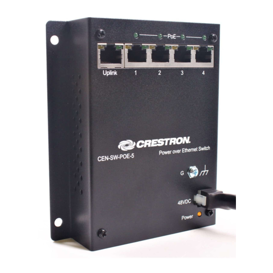
5-Port Power over Ethernet Switch Physical Description This section provides information on the connections and indicators available on your CEN-SW-POE-5. CEN-SW-POE-5 Physical View 4 • 5-Port Power over Ethernet Switch: CEN-SW-POE-5 Crestron CEN-SW-POE-5 Installation Guide – DOC. 6694A... - Page 9 Crestron CEN-SW-POE-5 CEN-SW-POE-5 Overall Dimensions Front View 5.06 in (12.86 cm) Bottom View 1.17 in (2.97 cm) Installation Guide – DOC. 6694A 5-Port Power over Ethernet Switch 3.62 in (9.18 cm) 4.66 in (11.82 cm) 5-Port Power over Ethernet Switch: CEN-SW-POE-5 • 5...
- Page 10 5-Port Power over Ethernet Switch Crestron CEN-SW-POE-5 CEN-SW-POE-5 Connectors & Indicators 6 • 5-Port Power over Ethernet Switch: CEN-SW-POE-5 Installation Guide – DOC. 6694A...
- Page 11 Crestron CEN-SW-POE-5 Connectors & Indicators CONNECTORS & INDICATORS Uplink AMBER GREEN (Continued on following page) Installation Guide – DOC. 6694A 5-Port Power over Ethernet Switch DESCRIPTION (1) 8-wire RJ-45 connector with 2 LED indicators; 10BaseT/100BaseTX Ethernet port; Amber LED indicates 100BaseT link status;...
- Page 12 Connectors & Indicators (Continued) CONNECTORS & INDICATORS PoE (1-4) AMBER GREEN AMBER (Continued on following page) 8 • 5-Port Power over Ethernet Switch: CEN-SW-POE-5 Crestron CEN-SW-POE-5 DESCRIPTION (4) 8-wire RJ-45 connectors with 2 LED indicators; GREEN 10BaseT/100BaseTX PoE ports for power and data;...
- Page 13 Crestron CEN-SW-POE-5 Connectors & Indicators (Continued) CONNECTORS & INDICATORS 48VDC Power Due to the inherent voltage drop over copper wire, a maximum of 12.9 W is guaranteed to be received by the PoE powered device over a cable run length of 328 feet (100 meters).
-
Page 14: Industry Compliance
Connect the equipment into an outlet on a circuit different from that to which the receiver is connected. Consult the dealer or an experienced radio/TV technician for help. 10 • 5-Port Power over Ethernet Switch: CEN-SW-POE-5 Crestron CEN-SW-POE-5 (E312979) Installation Guide – DOC. 6694A... -
Page 15: Setup
Crestron CEN-SW-POE-5 Setup Network Wiring When wiring the Ethernet network, use Category 5 (CAT5) wiring. CAT5 wiring is a twisted pair cable designed for Ethernet networks. These networks operate at speeds of up to 100 Megabits per second (Mbps) using the 100BaseT standard. -
Page 16: Installation
Mounting using the supplied rack screws and washers. Either the left or right flange of the switch can be used to mount the unit to the rack. To mount the CEN-SW-POE-5 to a rack (refer to the illustration below): 1. Position either the left or right mounting flange so that its holes align with the holes in the rack. - Page 17 Crestron CEN-SW-POE-5 Wall The CEN-SW-POE-5 can be mounted to a wall. To mount the device to a Mounting wall, use the four supplied 3/16 x 1-1/4” pan head Phillips drywall screws (refer to the illustration below). Wall Mounting (4) Screws, 3/16 x 1¼”...
-
Page 18: Hardware Hookup
• Use Crestron power supplies for Crestron equipment. • The included cable(s) cannot be extended. Hardware Connections for the CEN-SW-POE-5 UPLINK: TO NETWORK HUB OR SWITCH 14 • 5-Port Power over Ethernet Switch: CEN-SW-POE-5 Crestron CEN-SW-POE-5 PoE (1-4): TO CRESTRON OR THIRD-PARTY 10BaseT/100BaseTX 802.3af-COMPLIANT POWERED DEVICES Installation Guide –... -
Page 19: Problem Solving
Crestron CEN-SW-POE-5 Problem Solving Troubleshooting The following table provides corrective action for possible trouble situations. If further assistance is required, please contact a Crestron customer service representative. CEN-SW-POE-5 Troubleshooting TROUBLE Power LED does not illuminate. Green LED on Ethernet port does not illuminate. - Page 20 Green LED on Ethernet port does not illuminate. (Continued) PoE LED does not illuminate. 16 • 5-Port Power over Ethernet Switch: CEN-SW-POE-5 Crestron CEN-SW-POE-5 POSSIBLE CAUSE(S) Network cable is not the proper length. Fault exists with the network cable. Port is not functioning.
-
Page 21: Reference Documents
Crestron CEN-SW-POE-5 Reference Documents The latest version of all documents mentioned within the guide can be obtained from the Crestron website (www.crestron.com/manuals). This link will provide a list of product manuals arranged in alphabetical order by model number. List of Related Reference Documents... -
Page 22: Return And Warranty Policies
All brand names, product names and trademarks are the sole property of their respective owners. Windows is a registered trademark of Microsoft Corporation. Windows95/98/Me/XP/Vista and WindowsNT/2000 are trademarks of Microsoft Corporation. 18 • 5-Port Power over Ethernet Switch: CEN-SW-POE-5 Crestron CEN-SW-POE-5... - Page 23 Crestron CEN-SW-POE-5 5-Port Power over Ethernet Switch This page is intentionally left blank. 5-Port Power over Ethernet Switch: CEN-SW-POE-5 • 19 Installation Guide – DOC. 6694A...
- Page 24 Crestron Electronics, Inc. Installation Guide – DOC. 6694A 15 Volvo Drive Rockleigh, NJ 07647 (2021172) Tel: 888.CRESTRON 08.08 Fax: 201.767.7576 Specifications subject to www.crestron.com change without notice.
Need help?
Do you have a question about the Crestron CEN-SW-POE-5 and is the answer not in the manual?
Questions and answers