Table of Contents
Advertisement
Quick Links
Advertisement
Table of Contents

Related Manuals for Crestron CNX-PVID8x4


Summary of Contents for Crestron CNX-PVID8x4
- Page 1 Crestron CNX-PVID8x4 Video Distribution Switch Operations Guide...
- Page 2 This document was prepared and written by the Technical Documentation department at: Crestron Electronics, Inc. 15 Volvo Drive Rockleigh, NJ 07647 1-888-CRESTRON All brand names, product names, and trademarks are the property of their respective owners. ©2004 Crestron Electronics, Inc.
-
Page 3: Table Of Contents
Crestron CNX-PVID8x4 Contents Professional Video Distribution Switch: CNX-PVID8x4 Introduction ... 1 Features and Functions ... 1 Specifications ... 3 Physical Description... 4 Industry Compliance ... 8 Setup ... 8 Network Wiring... 8 Identity Code ... 9 Cabling and Jumpers ... 10 Rack Mounting ... -
Page 5: Professional Video Distribution Switch: Cnx-Pvid8X4
Fully integrated with the Crestron control system as a network device, the CNX-PVID8x4 is a key component in the Crestron Home throughout the home. - Page 6 The CNX-PVID8x4 is designed with three levels of video inputs and outputs, each highly configurable for a variety of video formats. Each of the three levels of switcher boards implements a video matrix with 16 RCA inputs and eight RCA outputs for direct single ended video connection to local display devices.
-
Page 7: Specifications
CNX-PVID8x4 used without Crestron Room Solution Box In this system, the CNX-PVID8x4 has an incredible amount of flexibility with respect to making connections to all three types of video sources. For example, it is possible to have a composite source connected to INPUT 1, level 1 and an S-video source connected to INPUT 1, levels 2 and 3, simultaneously. -
Page 8: Physical Description
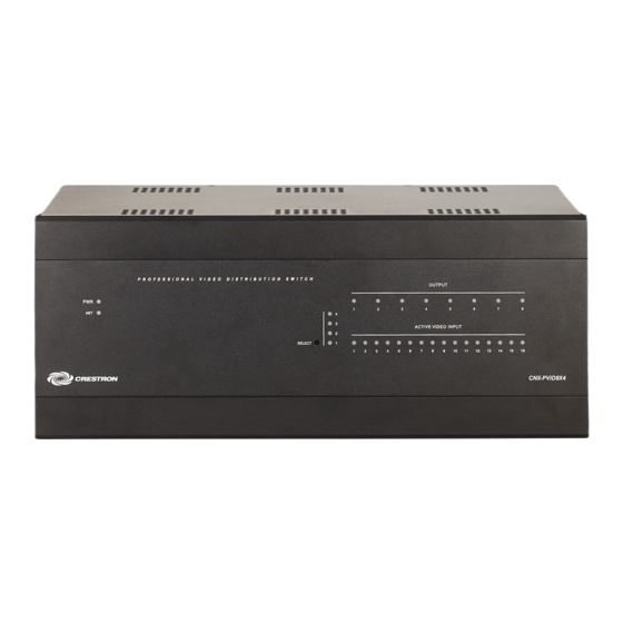
Professional Video Distribution Switch Physical Description The CNX-PVID8x4 is housed in a black enclosure with labeling on the front and rear panels. LEDs on the front of the unit indicate the unit's status. All connections are made to the back of the unit. Refer to the following illustrations. - Page 9 These feet are to be attached on the base of the unit for stability and to prevent slippage. CNX-PVID8x4 Ports All connections to the CNX-PVID8x4 are made through the ports on the rear panel. Refer to the following illustrations and descriptions. Operations Guide - DOC. 8166A...
- Page 10 There are four levels of 16 inputs, each input has two RCA jacks connected in parallel (one for video input, one for termination or loop-through), which is used to connect independent video sources to the CNX-PVID8x4. Each connector is supplied with RCA terminators (75 ohm). The terminators should remain attached unless the INPUT connectors of multiple units are connected (loop-through).
- Page 11 This 4-pin terminal block connector is used to connect the CNX-PVID8x4 to the Cresnet CNX-PVID8x4 Indicators There are 30 LED indicators located on the front panel of the CNX-PVID8x4, and one on the back panel. Refer to the following illustration and descriptions. CNX-PVID8x4 Indicators...
-
Page 12: Industry Compliance
CNX-PVID8x4 Pushbuttons There are two pushbuttons on the CNX-PVID8x4 (one on the front panel and one on the back panel). The front panel SELECT pushbutton allows for local selection of the boards (levels 1 through 4). Four indicators are used as feedback. The rear panel SETUP pushbutton is for future use and is not defined at the time of printing. -
Page 13: Identity Code
SIMPL Windows procedure. Refer to the note on page 31 for a The Net ID of the CNX-PVID8x4 has been factory set to 41. The Net IDs of definition of Viewport. multiple CNX-PVID8x4s in the same system must be unique. Net IDs are changed from a personal computer (PC) via the Crestron Viewport. -
Page 14: Cabling And Jumpers
Network Devices in the Viewport (alternately, select F4). Cabling and Jumpers Out of the box, the CNX-PVID8x4 provides four 16x8 crosspoint boards that can be operated independently or in parallel. However, versatility was built into the unit. Depending on how the four boards are cabled and/or jumpered, the unit can be used in different hardware configurations. -
Page 15: Rack Mounting
8. Tighten screws to finger-tight then, using a #2 Phillips screwdriver, tighten an additional 1/8-turn. • The unit should be mounted at the bottom of the rack if it is the only unit in the rack. Professional Video Distribution Switch: CNX-PVID8x4 • 11 JUMPER HOLDER STORES REMOVED JUMPERS... -
Page 16: Stacking
Ear Attachment for Rack Mounting (Side View of Unit) Stacking Four "feet" are provided with the CNX-PVID8x4 so that if the unit is not rack mounted, the rubber feet can provide stability when the unit is placed on a flat surface or stacked. -
Page 17: Hardware Hookup
NOTE: For specific details regarding input connections, refer to "Hardware Configurations" on page 14 if the CNX-PVID8x4 connects to Crestron Room Solution Boxes within the system. NOTE: Refer to "Network Wiring" on page 8 when making connections to the port labeled CRESNET. -
Page 18: Hardware Configurations
Professional Video Distribution Switch Hardware Configurations NOTE: The hardware configurations described in the following sections only apply to systems where the CNX-PVID8x4 connects to Crestron Room Solution Boxes. The Crestron AppBuilder can generate a program that fits into one of these configurations. - Page 19 16 sources. The illustration after this paragraph provides a visual depiction of a system that utilizes the CNX-PVID8x4 and contains a combination of 16 or fewer composite, S-video, and component sources. Some of the sources also include digital audio.
- Page 20 (up to 32, when there is no S-video) and S-video (up to 16, maximum). The illustration after this paragraph provides a visual depiction of a system that utilizes the CNX-PVID8x4 in the composite/S-video only configuration. Some of the sources also include digital audio. Notice that S-video sources can only be connected to input 1 through 16 (connect Y to level 1 and C to level 2).
- Page 21 NOTE: THE LABELING OF INPUTS 17 SOURCES CAN CONNECT TO LEVEL 1) THROUGH 32 BECOMES USEFUL Professional Video Distribution Switch: CNX-PVID8x4 • 17 DIGITAL AUDIO (IF AVAILABLE): PHYSICALLY CONNECTS TO LEVEL 4 AND IS SWITCHED WITH LEVELS 1&2 OR LEVEL 3, BUT NOT LEVELS 1,2,&3 TOGETHER.
- Page 22 LOGICAL DEPICTION: INPUTS LEVEL 4 LEVEL 3 LEVEL 2 LEVEL 1 18 • Professional Video Distribution Switch: CNX-PVID8x4 COMPOSITE SOURCES*: PHYSICALLY CONNECT TO LEVEL 3 (INPUTS 1 THROUGH 8), BUT ARE LOGICALLY AN EXTENSION OF LEVEL 1. INPUT C R E...
-
Page 23: Signal Distribution To More Than Eight Rooms
Crestron CNX-PVID8x4 Signal Distribution to More than Eight Rooms Each CNX-PVID8x4 is capable of distributing video to eight rooms, maximum. It is possible to expand distribution to more rooms, if additional CNX-PVID8x4s are introduced to the system. Crestron recommends a maximum of four CNX-PVID8x4s per system. -
Page 24: Programming Software
The latest software is available from the Downloads | Software Updates section of the Crestron website (www.crestron.com). The following are recommended software version requirements for the PC: 20 • Professional Video Distribution Switch: CNX-PVID8x4 -based programming software. The ™... -
Page 25: Programming With Crestron Appbuilder
Programming with SIMPL Windows NOTE: The following are acceptable file extensions for programs that include a CNX-PVID8x4, developed for specific control system types: SIMPL Windows is Crestron's software for programming Crestron control systems. It provides a well-designed graphical environment with a number of workspaces (i.e., windows) in which a programmer can select, configure, program, test, and... - Page 26 System Views. Refer to “CNX-PVID8x4 Symbols” on page 23 for details about each symbol. NOTE: The first CNX-PVID8x4 in a system is preset with a Net ID of 41 when its symbol is dragged into the upper pane of System Views. Additional units are assigned different Net ID numbers as they are added.
-
Page 27: Cnx-Pvid8X4 Symbols
For Net ID hardware setting details, refer to “Identity Code” on page 9. CNX-PVID8x4 Symbols The inputs to the CNX-PVID8x4 symbol require the analog equivalent (typically 1 through 16, but could go up to 32) so that the video source physically connected to a given input can be switched to the specified output. - Page 28 Professional Video Distribution Switch Detail View of the CNX-PVID8x4 Symbol CNX-PVID8x4 Symbol Input Descriptions 24 • Professional Video Distribution Switch: CNX-PVID8x4 INPUT(S) Src-For-Out-1-Level-1 Provide the analog equivalent (1 through 16) via the Analog through Src-For-Out- Initialize symbol (decimal format) on this line so that the...
- Page 29 This symbol designation allows the programmer to attach inputs and outputs to the CNX-PVID8x4 when it is configured as four independent levels (16 input to eight outputs). On each level, the 16 inputs can be switched to any of the eight outputs on the same level.
- Page 30 This is the equivalent of extending level 1 with 16 additional inputs. Detail View of the CNX-PVID8x4J13 Symbol CNX-PVID8x4J13 Symbol Input Descriptions 26 • Professional Video Distribution Switch: CNX-PVID8x4 INPUT(S) Src-For-Out-1-Level-1 Provide the analog equivalent (1 through 32) via the Analog...
- Page 31 This symbol allows the programmer to attach inputs and outputs to the CNX-PVID8x4 when it is configured as three levels (one with 32 inputs to eight outputs and the other two with 16 inputs to eight outputs). On level 1, the 32 inputs can be switched to any of the eight outputs on the same level.
- Page 32 Detail View of the CNX-PVID8x4J13S Symbol CNX-PVID8x4J13S Symbol Input Descriptions (continued on next page) 28 • Professional Video Distribution Switch: CNX-PVID8x4 INPUT(S) Src-For-Out-1-Level-1 Provide the analog equivalent (1 through 24) via the Analog...
- Page 33 This symbol allows the programmer to attach inputs and outputs to the CNX-PVID8x4 when it is configured as four levels with varying quantities of inputs (one with 24 inputs to eight outputs, two with 16 inputs to eight outputs, and the other with eight inputs to eight outputs).
-
Page 34: Example Program
LEVEL 2 LEVEL 1 DEPICTION OF SYMBOL IN SIMPL WINDOWS: Example Program The example program for the CNX-PVID8x4 is available from the Crestron website (www.crestron.com/exampleprograms). Search for PVID8_Video_Switcher_Test_ program_on_Pro2.zip. 30 • Professional Video Distribution Switch: CNX-PVID8x4 VIA THE ANALOG INITIALIZE... -
Page 35: Uploading And Upgrading
Crestron Viewport may be preferred over development tools when uploading programs and projects. The following sections define how one would upload a SIMPL Windows program or upgrade the firmware of the CNX-PVID8X4. However, before attempting to upload or upgrade, it is necessary to establish communications. Communication Settings NOTE: For laptops and other PCs without a built-in RS-232 port, Crestron recommends the use of PCMCIA cards, rather than USB-to-serial adapters. - Page 36 Professional Video Distribution Switch Typical Connection Diagram when Uploading Setup | Communications Settings Command 32 • Professional Video Distribution Switch: CNX-PVID8x4 1. Open the Crestron Viewport. Either launch the stand-alone version of Viewport, or start SIMPL Windows or VT Pro-e, and from the menu bar, select Tools | Viewport.
-
Page 37: Uploading A Simpl Windows Program
1. Verify that the procedure for “Communication Settings” that begins on page 31 has been performed. 2. As shown after this step, select File Transfer | Send Program (alternatively, press Alt+P) from the Viewport menu. Professional Video Distribution Switch: CNX-PVID8x4 • 33... - Page 38 “Send Program” window. “Send Program” Window 34 • Professional Video Distribution Switch: CNX-PVID8x4 3. The “Send Program” window appears, as shown after this step. Click Browse, locate the compiled file (.spz for PRO2), and click Open. This will display the program's header information and enable one or both of the What to Send check boxes.
-
Page 39: Firmware Upgrade
Crestron CNX-PVID8x4 Firmware Upgrade A firmware upgrade file has the To take advantage of all the CNX-PVID8X4 features, it is important that the unit extension .upg. contains the latest firmware available. Therefore, please check the Crestron website (http://www.crestron.com/downloads/software_updates.asp) for the latest version of firmware. -
Page 40: Problem Solving
Verify that cables plugged into NET ports are not receiving secure. power. Improper Net ID. Verify that CNX-PVID8x4 Net ID matches Net ID in the software program. Refer to "Identity Code" in this Operations Guide. Loose network Verify that cable plugged into NET port is connection. -
Page 41: Further Inquiries
Future Updates As Crestron improves functions, adds new features, and extends the capabilities of the CNX-PVID8x4, additional information and programming examples may be made available as manual updates. These updates are solely electronic and serve as intermediary supplements prior to the release of a complete technical documentation revision. -
Page 42: Return And Warranty Policies
All brand names, product names, and trademarks are the sole property of their respective owners. Windows is a registered trademark of Microsoft Corporation. Windows95/98/Me/XP and WindowsNT/2000 are trademarks of Microsoft Corporation. 38 • Professional Video Distribution Switch: CNX-PVID8x4 Crestron CNX-PVID8x4 Operations Guide - DOC. 8166A... - Page 43 Crestron CNX-PVID8x4 Professional Video Distribution Switch This page intentionally left blank. Professional Video Distribution Switch: CNX-PVID8x4 • 39 Operations Guide - DOC. 8166A...
- Page 44 Crestron Electronics, Inc. Operations Guide – DOC. 8166A 15 Volvo Drive Rockleigh, NJ 07647 04.04 Tel: 888.CRESTRON Fax: 201.767.7576 Specifications subject to www.crestron.com change without notice.
Need help?
Do you have a question about the CNX-PVID8x4 and is the answer not in the manual?
Questions and answers