Table of Contents
Advertisement
Quick Links
Advertisement
Table of Contents

Subscribe to Our Youtube Channel
Related Manuals for TYAN TN73-B8037


Summary of Contents for TYAN TN73-B8037
- Page 1 TN73-B8037 Service Engineer’s Manual...
- Page 2 TECHNOLOGY CORPORATION and has been reviewed for accuracy and reliability prior to printing. MITAC assumes no liability whatsoever, and disclaims any express ® or implied warranty, relating to sale and/or use of TYAN products including liability or warranties relating to fitness for a particular purpose or merchantability. MITAC retains the right to make changes to produce descriptions and/or specifications at any time, without notice.
- Page 3 FCC Declaration ● Notice for the USA Compliance Information Statement (Supplier’s Declaration of Conformity, SDoC) FCC Part 15: This device complies with part 15 of the FCC Rules. This device complies with Part 15 of the FCC Rules. Operation is subject to the following conditions: ‧This device may not cause harmful interference.
- Page 4 Warning This equipment is compliant with Class A of CISPR 32. In a residential environment this equipment may cause radio interference. CAUTION Lithium battery included with this board. Do not puncture, mutilate, or dispose of battery in fire. There will be danger of explosion if battery is incorrectly replaced. Replace only with the same or equivalent type recommended by manufacturer.
- Page 5 This manual is intended for skilled person with hardware knowledge of computers. Components inside the compartments should be serviced only by a skilled person. This manual is aimed to provide you with instructions on installing your TYAN TN73-B8037. How this guide is organized...
- Page 6 Safety and Compliance Information Before installing and using TYAN TN73-B8037, take note of the following precautions: ·Read all instructions carefully. ·Do not place the unit on an unstable surface, cart, or stand. ·Do not block the slots and opening on the unit, which are provided for ventilation.
- Page 7 You must become familiar with the safety information in this guide before you install, operate, or service TYAN products. Symbols on Equipment Caution. This symbol indicates a potential hazard.
- Page 8 · Do not attempt to move a fully loaded rack. Remove equipment from the rack before moving it. · Do not attempt to move a rack on an incline that is greater than 10 degrees http://www.tyan.com...
- Page 9 This will reduce the risk of personal injury, fire, or damage to the equipment. The total rack load should not exceed 80 percent of the branch circuit rating. Consult the electrical authority having jurisdiction over your facility wiring and installation requirements. http://www.tyan.com...
- Page 10 · Dispose of used batteries according to the instructions of the manufacturer. Do not dispose of batteries with the general household waste. To forward them to recycling or proper disposal, use the public collection system or return them to TYAN, your authorized TYAN partner, or their agents. http://www.tyan.com...
- Page 11 Equipment Modifications · Do not make mechanical modifications to the system. TYAN is not responsible for the regulatory compliance of TYAN equipment that has been modified. Equipment Repairs and Servicing · The installation of internal options and routine maintenance and service of...
-
Page 12: Table Of Contents
Table of Contents Chapter 1: Overview ................ 15 About the TYAN TN73-B8037 ..........15 Product Model ................ 15 Features.................. 16 Standard Parts List ..............22 1.4.1 Box Contents ..............22 1.4.2 Accessories ..............22 About the Product ..............23 1.5.1 System Front View ............ - Page 13 Save & Exit ................171 Appendix I: Installing IO Plate for OCP Card ......173 Appendix II: Cable Connection Tables ........177 Appendix III: Fan and Temp Sensors ........... 178 Appendix IV: FRU Parts Table ............182 Appendix V: Technical Support ............ 184 http://www.tyan.com...
- Page 14 NOTE http://www.tyan.com...
-
Page 15: Chapter 1: Overview
PCI-E bus implementation. The TN73-B8037 not only empowers your company in nowadays IT demand but also offers a smooth path for future application usage. ® TYAN also offers the TN73-B8037 in a version that can support up to sixteen hot-swap 2.5” SATA HDD/SSD, or sixteen hot-swap 2.5”... -
Page 16: Features
80 plus Platinum Redundancy When about 180W CPUs are deployed. The 4-node system may not support redundancy. Notification Please contact Tyan Technical Support for additional information. Q'ty / Socket Type (1) AMD Socket SP3 per node (1) AMD EPYC™ 7002 Series Processor... - Page 17 LRDIMM 3DS Memory channel 8 Channels per CPU Memory voltage 1.2V PCI-E (2) PCI-E x16 slots Pre-install TYAN Riser (1) M8037T73-R16-1L riser card for (1) Card HH/HL, (1) M8037T73-L16-1L riser card for (PCI-E Gen4) (1) HH/HL Expansion Slots (1) PCI-E Gen3 x16 OCP 2.0 slot Others (conn.A+conn.B)
- Page 18 10° C ~ 35° C (50° F~ 95° F) Operating Non-operating Temp. - 40° C ~ 70° C (-40° F ~ 158° F) Environment In/Non-operating Humidity 90%, non-condensing at 35° C RoHS RoHS 6/6 Compliant Barebone (1) TN73-B8037 Barebone Package Contains Manual (1) Quick Installation Guide http://www.tyan.com...
- Page 19 Interface External Drive Bay The SAS/SATA HDD backplane is connected to onboard SATA Notification connection by default. Please contact Tyan technical support if a discrete SAS HBA/RAID adapter is required. System Cooling Configuration (3) 4cm fans per node Type CRPS...
- Page 20 LRDIMM 3DS Memory channel 8 Channels per CPU Memory voltage 1.2V PCI-E (2) PCI-E x16 slots Pre-install TYAN Riser (1) M8037T73-R16-1L riser card for (1) Card HH/HL, (1) M8037T73-L16-1L riser (PCI-E Gen4) card for (1) HH/HL Expansion Slots (1) PCI-E Gen3 x16 OCP 2.0 slot Others (conn.A+conn.B)
- Page 21 In/Non-operating 90%, non-condensing at 35° C Humidity RoHS RoHS 6/6 Compliant Barebone (1) TN73-B8037 Barebone Package Contains Manual (1) Quick Installation Guide NOTE: 1. The specifications are subject to change without prior notice. 2. Please visit our website for the latest specifications.
-
Page 22: Standard Parts List
Standard Parts List This section describes TN73-B8037 package contents and accessories. Open the box carefully and ensure that all components are present and undamaged. The product should arrive with packaged as illustrated below. 1.4.1 Box Contents If any items are missing or appear damaged, contact your retailer or browse to TYAN’s website for service:... -
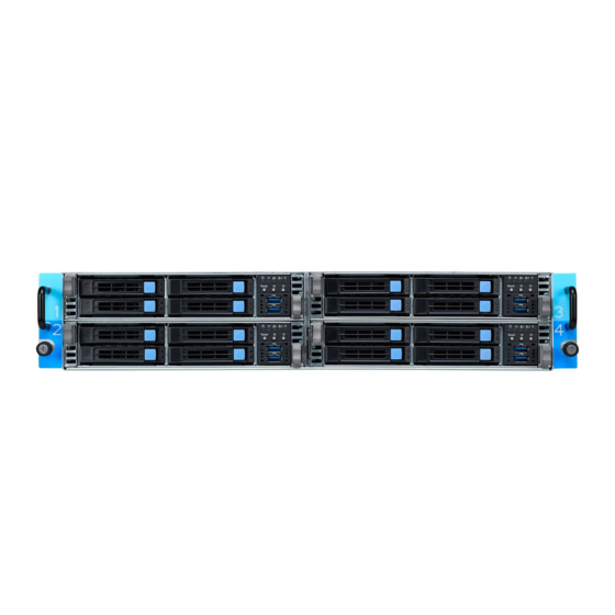
Page 23: About The Product
About the Product The following views show you the product. 1.5.1 System Front View http://www.tyan.com... - Page 24 HDD TRAY LED INDICATION HDD Status Activity LED: Green Status LED: Red Driver present, NO Activity On Solid Driver Present with Activity Blinking Drive Fail Don’t care Solid ON Drive Identify Don’t care Blinking @1Hz Drive Rebuild Don’t care Blinking @4Hz http://www.tyan.com...
-
Page 25: System Rear View
LP PCIe x16 Dedicate to OCP Card LP PCIe x16 Display Port LP PCIe x16 VGA Port LP PCIe x16 LAN2 LP PCIe x16 LAN1 LP PCIe x16 ID LED State Color Description Blue System identified ID LED System not identified http://www.tyan.com... - Page 26 (Link/Activity) (Speed) No Link Solid Green Solid Green Link 100 Mbps Blinking Green Solid Green Active Solid Green Solid Yellow Link 1000 Mbps (1Gps) Blinking Green Solid Yellow Active “Left” and “Right” are viewed from the rear panel. NOTE: http://www.tyan.com...
- Page 27 Blink AMBER Bus reading)),high power, high current, slow fan(Fan warning+/-20%RPM). AC present Only 12VSB on (PS off) or PS in Smart Redundant State Blink GREEN Output ON and OK http://www.tyan.com...
-
Page 28: System Top View
1.5.3 System Top View HDD Module& M1716G75-FPB Front Panel Board M1311T73-BP12E-4 HDD backplane Board M1629T73-D-PDB Power Distribution Board CPU Sockets Memory Slots Riser Card Bracket (M8037T73-L16-1L) Riser Card Bracket (M8037T73-R16-1L) http://www.tyan.com... -
Page 29: Chassis Dimensions
1.5.4 Chassis Dimensions http://www.tyan.com... -
Page 30: Chapter 2: Setting Up
Caution! To avoid damaging the motherboard and associated components, use torque force within the range kgf/cm (6.09 lb/in) on each mounting screw for motherboard installation. Do not apply power to the board if it has been damaged. http://www.tyan.com... -
Page 31: Precautions
Components and electronic circuit boards can be damaged by discharges of static electricity. Working on a system that is connected to a power supply can be extremely dangerous. Follow the guidelines below to avoid damage to TN73-B8037 or injury to yourself. -
Page 32: Installing Motherboard Components
CPUs, memory modules and add on cards. 2.1.1 Removing the Chassis Cover Follow these instructions to remove TN73-B8037 chassis cover. 1. Pinch the latch on the left side to pull out the node. 2. The left and right node are as below. -
Page 33: Removing The Air Duct
2.1.2 Removing the Air Duct 1. Release the two screws from the air duct. 2. Remove the air duct from the chassis. http://www.tyan.com... -
Page 34: Installing The Cpu And Heatsink
Note: The force frame will automatically eject after the captive screws are being released. By placing your both index fingers on the sides on the metal handle, pull to release the rail frame. Then lift the rail frame to its fully open position. Remove the external cap from the rail frame. http://www.tyan.com... - Page 35 During installation, observe the following: 1. Make sure to push the carrier frame with package towards the end of the rail frame until it clicks into place. 2. Do not drop the carrier frame or touch the package pad to avoid component damage. http://www.tyan.com...
- Page 36 7. Close the force frame. Then use a T20 Torx screwdriver to tighten the screws to secure the force frame in a sequential order (1 ->2->3). 8. To secure the heatsink, use a T30 Security Torx to tighten the screws. Tighten the four screws in a diagonal sequence to secure the heat sink. http://www.tyan.com...
-
Page 37: Installing The Memory
2. Align the memory module with the slot. When inserted properly, the memory slot locking levers lock automatically onto the indentations at the ends of the module. Follow the recommended memory population table to install the other memory modules. http://www.tyan.com... -
Page 38: Installing Hard Drives
2.1.5 Installing Hard Drives The TN73-B8037 supports sixteen 2.5” hot-swap HDD/SSDs. Follow these instructions to install a 2.5” HDD/SSD. Warning!!! Always install the hard disk drive to the chassis after the chassis has been secured on the rack. Press the locking lever latch. - Page 39 Open the lock to place the 2.5” hard disk drive into the HDD tray. Push the HDD to the left. Lock the tray lever to secure HDD. Reinsert the HDD tray into the chassis. Push to secure the locking lever until it clicks into place. http://www.tyan.com...
-
Page 40: Installing The Pci-E Card
Follow these instructions to install the PCI-E card. 1. Unscrew the riser card bracket. 2. Unscrew the riser bracket and remove the riser card bracket from the chassis. Unscrew the riser bracket and remove the riser card bracket from the chassis. http://www.tyan.com... - Page 41 4. Unscrew to remove the dummy brackets. Insert the PCI-E card into the riser card bracket and screw it firmly. Follow the same procedures to insert the card to the other side of the riser card bracket if necessary. http://www.tyan.com...
- Page 42 6. The same procedure to install the PCIE card to the second riser card. 7. Reposition and screw the riser card bracket into the chassis. http://www.tyan.com...
-
Page 43: Rack Mounting
Rail screw Pack x 1 2.2.1 Installing the Server in a Rack Follow these instructions to mount the TYAN TN73-B8037 into an industry standard 19" rack. NOTE: Before mounting the TYAN TN73-B8037 in a rack, ensure that all internal components have been installed and that the unit has been fully tested. - Page 44 Repeat steps 2 to 4 to secure the sliding rail to the other side of the server. Detach inner rail from standoff Pull the latch upward and remove the keyhole from standoff and slide inner rail forward to remove inner rail. http://www.tyan.com...
- Page 45 Installing the Outer Rails to the Unit Secure the outer rails to the rack on each side. http://www.tyan.com...
- Page 46 Detach bracket from rack post to Release the outer rails from the rack on each side. Please repeat the detach steps for the other side. http://www.tyan.com...
- Page 47 Rack Mounting the Server 1. Pull the middle rail fully extended in lock position, ensure ball bearing retainer is located at the front of the middle rail. Insert the inner rails to the outer rail. Push the chassis to the rack. http://www.tyan.com...
-
Page 48: Removing The Server From Rack
Secure the chassis to the rack. 2.2.2 Removing the Server from Rack 1. Loosen shipping screws to pull out chassis. http://www.tyan.com... - Page 49 When the inner rails come to a stop, pull the tab to release the latch and push the whole system in. 3. Push tab to slide the middle rail back. http://www.tyan.com...
- Page 50 NOTE http://www.tyan.com...
-
Page 51: Chapter 3: Replacing Pre-Installed Components
This chapter explains how to replace the pre-installed components, including the Motherboard, M1716G75-FPB Front Panel Board, M1311T73-BP12E-4 Power Distribution board, Backplane, M1629T73-D-PDB M1630T73-D-PBP1/ M1630T73-D-PBP2 Power Backplane Board. M1632T73-EMB, M8037T73-R16-1L M8037T73-L16-1L Riser cards, System fan and Power supply unit etc. Disassembly Flowchart The following flowchart outlines the disassembly procedure. http://www.tyan.com... -
Page 52: Removing The Cover
Removing the Cover Before replacing any parts you must remove the chassis cover first. Follow Chapter 2.1.1 to remove the cover of the TN73-B8037. Replacing Motherboard Components Follow these instructions to replace motherboard components, including the motherboard. 3.4.1 Replacing the Riser Card... - Page 53 Unscrew the riser bracket and remove the riser card bracket from the chassis. Unscrew the M8037T73-R16-1L riser card to replace with a new one. Unscrew the M8037T73-L16-1L riser card to replace with a new one. Follow the steps described earlier in reverse to reinstall the riser card bracket. http://www.tyan.com...
-
Page 54: Pci-E Riser Cards Specification
3.4.2 PCI-E Riser Cards Specification 3.4.3 Connector Pin Definition (M8037T73-L16-1L) Location Definition PCIE1 PCIe X16 SLOT 3.4.4 Connector Pin Definition (M8037T73-R16-1L) Location Definition PCIE2 PCIe X16 SLOT http://www.tyan.com... -
Page 55: Replacing The Front Panel Board
Replacing the Front Panel Board Follow these instructions to replace the M1716G75-FPB Front Panel Board. Unscrew the front panel tray. Pull the front panel tray forward and disconnect the cables. http://www.tyan.com... - Page 56 Unscrew the front panel board from the front panel tray for a new one. Reinstall the Front Panel Board into the chassis following the steps in reverse. http://www.tyan.com...
-
Page 57: Front Panel Board Features
Form Factor 28 x 35.4 x 1.6 (mm), 4-layer PCB I/O: (2) USB3.0 Port LED Indicators: (1) HDD LED (1) Warning LED Specifications (2) LAN LED (1) Power/ID LED Switch: (1) Reset Button (1) ID Button (1) Power Button http://www.tyan.com... -
Page 58: Connector Definition
3.5.2 Connector Definition Location Definition HDD_LED HDD LED BMC_EVENT_LED Warning LED LAN1_LED LAN1 LED LAN2_LED LAN2 LED ID_PW_LED Power/ID LED USB3.0 Port USB3.0 Port Reset Button ID Button Power Button Front Panel Control Board Connector USB3.0 Connector http://www.tyan.com... -
Page 59: Replacing The System Fan
Replacing the System Fan Follow these instructions to replace the fan. Disconnect the fan cables from the mainboard. Tear off the back gum from the fan module. http://www.tyan.com... - Page 60 Take off the mylar from the fan module. Remove the fan from the system. Reinstall the fan(s) into the chassis following the procedures described earlier in reverse order. http://www.tyan.com...
-
Page 61: Replacing The Hdd Backplane Board
Disconnect all cables connected to the M1311T73-BP12E-4 HDD Backplane. Unscrew the HDD Backplane bracket and lift the bracket. Unscrew the backplane board from the bracket. Replace a new Backplane Board and reinstall it into the chassis following the above steps in reverse. http://www.tyan.com... -
Page 62: Hdd Backplane Board Features
3.7.1 HDD Backplane Board Features Front View Rear View (4) 2.5” HDD/SSD supported, speed up to SAS 12G/s & SATA 6G/s. Specifications (1) ATX 2*4P power connector Overview (3) mini SAS connector (1) FAN Header support 3 system FAN. http://www.tyan.com... -
Page 63: Replacing The Power Distribution Board
Power Distribution Board in your system. Disconnect all cables connected to the power distribution board. Unscrew to take off the power distribution board and replace with a new one. Insert the PDB into the chassis following the above procedures in reverse. http://www.tyan.com... -
Page 64: Power Distribution Board Features
(1) PDB to PBP2 signal and Power connector(J30) 3.8.2 Connector Definition J30: PDB to PBP2 signal and Power connector DEFAULT DEFAULT NODE_SYS_PWROK A4 MCU_NODE_PSU_ALERT_N NODE_BMC_HB B4 SYS_NODE_PSU_PWRGD NODE_PSON_N NODE_BMC_I2C_SCL NODE_PRSNT_N P12V_STBY NODE_BMC_EXTRST_N NODE_RESET_MCU_N NODE_BMC_I2C_SDA FM_MCU_HB_OUT FM_MCU_PSON_NODE_N NODE_ADM1278_FAULT_N NODE_ADM1278_PWRGD P1_1~8 P2_1~8 P12V_PSU GND1 GND2 http://www.tyan.com... - Page 65 DEFAULT PIN PIN DEFAULT NODE_BMC_I2C_SCL 2 NODE_BMC_I2C_SDA MCU_NODE_PSU_ALERT_N 3 6 NODE_RESET_MCU_N 8 FM_MCU_HB_OUT NODE_SYS_PWROK 10 SYS_NODE_PSU_PWRGD NODE_BMC_HB NODE_PSON_N 11 12 ADM1278_FAULT_N 13 14 ADM1278_PWRGD NODE_BMC_EXTRST 15 16 FM_MCU_PSON_NODE_N J3: PDB to MB Micro-Fit Power connector DEFAULT DEFAULT P12V_STBY P12V http://www.tyan.com...
-
Page 66: Replacing The Power Supply
Follow these instructions to replace the power supply module in your system. Press the latch to pull the power supply out. After replacing a new power supply, press and hold the latch to push the power supply back into the chassis. http://www.tyan.com... -
Page 67: Replacing The Power Backplane Board
3.10 Replacing the Power Backplane Board Follow these instructions to replace the M1630T73-D-PBP1/ M1630T73-D-PBP2 Power Backplane Board, M1632T73-EMB Enclosure Management Board. Release the rotary screw. Release the lever latch. Pull out the power bracket. http://www.tyan.com... - Page 68 Disconnect the power cable. Unscrew to replace with a new power backplane board. http://www.tyan.com...
- Page 69 Unscrew the M1632T73-EMB enclosure management board. Pull out the M1632T73-EMB enclosure management board. Pull out the M1630T73-D-PBP2 enclosure management board. http://www.tyan.com...
- Page 70 Pull out the M1630T73-D-PBP2 module. Unscrew to replace with a new power backplane board. Follow the steps described earlier in reverse order to reinstall the power backplane board tray into the chassis. http://www.tyan.com...
-
Page 71: Hdd Backplane Board Features
3.10.1 HDD Backplane Board Features Front View Rear View M1630T73-D-PBP2 Power Backplane Board (1) PBP2 link to EMB connector (J1) Specifications (1) PBP2 to PBP1Power connector(J2) Overview (4) PDP2 to PDB signal and Power connector( J2/J4/J5/J6 ) http://www.tyan.com... -
Page 72: Connector Definition
56 N3_RESET_MCU_N N2_RESET_MCU_N 58 P12V_STBY P12V_STBY 50 N3_BMC_EXTRST_N N2_BMC_EXTRST_N 62 FM_MCU_HB_OUT3 FM_MCU_HB_OUT2 64 SYS_N3_PSU_PWRGD SYS_N2_PSU_PWRGD 66 MCU_N3_PSU_ALERT_N MCU_N2_PSU_ALERT_N N2_BMC_I2C_SCL 68 N3_BMC_I2C_SCL N2_BMC_I2C_SDA 70 N3_BMC_I2C_SDA 72 EN_N3_P12VSB EN_N2_P12VSB 74 FM_MCU_PSON_N3_N FM_MCU_PSON_N2_N 76 N3_ADM1278_FAULT_N N2_ADM1278_FAULT_N N2_ADM1278_PWRGD 78 N3_ADM1278_PWRGD VCC3_SB 80 VCC3_SB http://www.tyan.com... - Page 73 J2: PBP2 to PBP1 Power connector DEFAULT DEFAULT P12V_STBY P12V_PSU J3/J4/J5/J6: PBP2 to PDB signal and Power connector DEFAULT DEFAULT NODE_SYS_PWROK MCU_NODE_PSU_ALERT_N NODE_BMC_HB SYS_NODE_PSU_PWRGD NODE_PSON_N NODE_BMC_I2C_SCL NODE_PRSNT_N P12V_STBY NODE_BMC_EXTRST_N NODE_RESET_MCU_N NODE_BMC_I2C_SDA FM_MCU_HB_OUT FM_MCU_PSON_NODE_N NODE_ADM1278_FAULT_N NODE_ADM1278_PWRGD P1_1~8 P2_1~8 P12V_PSU GND1 GND2 http://www.tyan.com...
- Page 74 Front View Rear View M1630T73-D-PBP1 Power Backplane Board (1) PBP1 link to EMB connector (J3) Specifications (1) PBP1 to PBP2 Power connector(J4) Overview (2) Power supply link connector (J1/J2) http://www.tyan.com...
-
Page 75: Connector Definition
J3: PBP1 and EMB link connector DEFAULT PIN PIN DEFAULT PDBSYS_PSU_PMBUS_SDA PDBU_P12V_SENSE PDBSYS_PSU_PMBUS_SCL PDBU_P12V_RETRUN PDBU_PSU_SMB_ALERT_N PDBU_PSU_PSON_N PDBU_PSU_PRSNT_N PDBU_PSU_PWROK 10 PDBL_P12V_SENSE P12V_STBY 12 PDBL_P12V_RETRUN P12V_STBY 14 PDBL_PSU_PSON_N PDBL_PSU_SMB_ALERT_N PDBL_PSU_PRSNT_N 16 PDBL_PSU_PWROK P12V_STBY 18 GND 20 VDD_33_STBY 22 VDD_33_STBY VDD_5_STBY VDD_5_STBY 24 VDD_33_STBY VDD_5_STBY 26 VDD_33_STBY http://www.tyan.com... - Page 76 J4: PBP1 to PBP2 Power connector Default Pin Pin Default 1 P12V_STBY 2 P12V_PSU 3 P12V_PSU 4 P12V_PSU 5 P12V_PSU 6 P12V_PSU 7 P12V_PSU 8 P12V_PSU 9 P12V_PSU 10 P12V_PSU 11 P12V_PSU 12 P12V_PSU http://www.tyan.com...
-
Page 77: Connector Definition
Front View M1632T73-EMB Power Backplane Board Specifications (1) MCU UART Pin Header (J21) Overview (1) MCU DEBUG Pin Header (J20) 3.10.4 Connector Definition J21: MCU UART Pin Header DEFAULT VCC3_SB UART_TX UART_RX http://www.tyan.com... -
Page 78: Disconnecting All Motherboard Cables
3.11 Disconnecting All Motherboard Cables Disconnect all cables connected to the motherboard. http://www.tyan.com... -
Page 79: Removing The Motherboard
After removing all of the aforementioned cables, follow the instructions below to remove the motherboard from the chassis. Remove the air duct, processor and heatsink if installed. Remove eight screws securing the motherboard to the chassis. Carefully lift the motherboard from the chassis. http://www.tyan.com... - Page 80 NOTE http://www.tyan.com...
-
Page 81: Chapter 5: Motherboard Information
Caution! To avoid damaging the motherboard and associated components, do not use torque force greater than 7kgf/cm (6.09 lb/in) on each mounting screw for motherboard installation. Do not apply power to the board if it has been damaged. http://www.tyan.com... -
Page 82: Board Image
Board Image S8037GM2NE This picture is representative of the latest board revision available at the time of publishing. The board you receive may not look exactly like the above picture. http://www.tyan.com... -
Page 83: Block Diagram
Block Diagram S8037 Block Diagram http://www.tyan.com... -
Page 84: Motherboard Mechanical Drawing
Motherboard Mechanical Drawing http://www.tyan.com... -
Page 85: Board Parts, Jumpers And Connectors
The board you receive may not look exactly like the above diagram. The DIMM slot numbers shown above can be used as a reference when reviewing the DIMM population guidelines shown later in the manual. For the latest board revision, please visit our web site at http://www.tyan.com. http://www.tyan.com... - Page 86 18. SYS_FAN_5-6 (J14) 6. NGFF/NGSFF 22x80mm Connector (CN1) 19. NGFF/NGSFF 22x80mm Connector (CN2) 20. Slim Line SAS 8x24; NVME; PCIe; Port x2 7. TYAN Module Header (J21) (CN3) 8. Slim Line SAS 4x24; SATA Port x2 (CN5) 21. Power Connector (J1) 9.
- Page 87 FAULT_LED1- HDD_LED- FAULT_LED2- PWR_SW# LAN1 ACTLED+ LAN1 ACTLED- RST_SW# SMBus SDA SMBus SCL SYS_ID_SW# INTRUSION# TEMP SENSOR LAN2 ACTLED+ NMI_SW# LAN2 ACTLED- DBG_HD1: TYAN Module Header Signal Signal P3V3 FRAME_N LAD0 LAD1 PLT_RST_N LAD2 LAD3 CLK_33M DBG_SERIRQ DBG_PRES_N VCC3_AUX TPM_ADDR_MB PCH_TPM_PP_EN http://www.tyan.com...
- Page 88 P0_TX_N P0_TX_P P1_TX_N P1_TX_P P0_N P0_P P1_N OC_N P1_P J18: PSMI Connector Signal Signal PSMI_SMBCLK PSMI_SMBDATA PSMI_ALERT_N KEY-PIN MCU_RSTN SYS_POWER_GOOD MCU_HB_OUT MGM_HEARTBEAT SYS_PSU_PWRGD SYS_POWER_ON_N ADM1278_FAULT_N SYSTEM_INTRUSION_N ADM1278_PWRGD MGM_RSTN MCU_PSON_N J64: BP Power Connector Signal Signal P12V P12V P12V P3V3_AUX http://www.tyan.com...
- Page 89 5. Reconnect power & power on system. NOTE: After flashing new BIOS please follow the following steps: Clear CMOS a. Clear CMOS b. Enter BIOS setup menu and load Default Settings. Then do a Save and Exit from setup. http://www.tyan.com...
-
Page 90: Thermal Interface Material
CPU lid (applying too much will actually reduce the cooling). NOTE: Always check with the manufacturer of the heat sink & processor to ensure that the thermal interface material is compatible with the processor and meets the manufacturer’s warranty requirements. http://www.tyan.com... -
Page 91: Tips On Installing Motherboard In Chassis
Some chassis include plastic studs instead of metal. Although the plastic studs are usable, MITAC recommends using metal studs with screws that will fasten the motherboard more securely in place. Below is a chart detailing what the most common motherboard studs look like and how they should be installed. http://www.tyan.com... - Page 92 http://www.tyan.com...
-
Page 93: Installing The Memory
Installing the Memory Before installing memory, ensure that the memory you have is compatible with the motherboard and processor. Check the TYAN Web site at http://www.tyan.com details of the type of memory recommended for your motherboard. (4+4) DIMM type DDR4 and supports MAX. capacity up to 4TB ... -
Page 94: Finishing Up
In the rare circumstance that you have experienced difficulty, you can find help by asking your vendor for assistance. If they are not available for assistance, please find setup information and documentation online at our website or by calling your vendor’s support line. http://www.tyan.com... -
Page 95: Chapter 6: Bios Setup
Select the previous value/setting of the field <+> Select the next value/setting of the field <F8> Load Fail Safe default configuration values of the menu <F3> Load the Optimal default configuration values of the menu <F4> Save and exit <Enter> Execute command or select submenu http://www.tyan.com... - Page 96 BIOS menus are continually changing due to continual BIOS updates over the product lifespan of the motherboard. The BIOS menus provided are current as of the date when this manual was written. Please visit TYAN’s website at http://www.tyan.com for information on BIOS updates available for this specific motherboard.
-
Page 97: Main Menu
Choose the system default language. System Date Set the Date. Use Tab to switch between Date elements. Default Ranges: Year: 2005-2099 Months: 1-12 Days: dependent on month System Time Set the Time. Use Tab to switch between Time elements. http://www.tyan.com... -
Page 98: Advanced Menu
This section facilitates configuring advanced BIOS options for your system. CPU Configuration CPU Configuration Parameters Onboard Device Configuration Onboard Device and Function Configuration PCIE Slot Configuration Onboard PCIE Slot Configuration Trusted Computing Trusted Computing Setting ACPI Settings System ACPI Parameters Redfish Host Interface Settings Redfish Host Interface Parameters. http://www.tyan.com... - Page 99 SATA Configuration SATA Devices Information NVDIMM Force Self Refresh NVDIMM Force Self Refresh Configuration Network Stack Configuration Network Stack Settings CSM Configuration Enable/Disable, Option ROM execution settings,etc. NVMe Configuration NVMe Device Options Settings SATA Configuration Configure the iSCSI parameters. http://www.tyan.com...
- Page 100 6.3.1 CPU Configuration SVM Mode Enable/Disable CPU Virtualization. Disabled / Enabled SMEE Control secure memory encryption enable Disabled Enabled Node 0 Information View Memory Information related to Node 0. http://www.tyan.com...
- Page 101 6.3.1.1 Node 0 Information Configuration http://www.tyan.com...
- Page 102 OnBoard LAN(B5720) Disabled / Enabled LAN1 OPROM Enable/Disable Load Option ROM For OnBoard LAN Disabled / Enabled LAN2 OPROM Enable/Disable Load Option ROM For OnBoard LAN Disabled / Enabled NMI Button Enable or Disable NMI Button Disabled / Enabled http://www.tyan.com...
- Page 103 PCIE Slot Configuration PCIE Slot Link Width Configuration OCP MEZZ A/B OCP MEZZ A/B x8 /x8 / x16 PCIe Riser 1 PCIe Riser 1 x4/x4/x4/x4 / x16 PCIe Riser 2 PCIe Riser 2 x4/x4/x4/x4 / x16 M.3#1 M.3#1 x4 / x2x2 http://www.tyan.com...
- Page 104 Auto / Gen 1 (2.5 GT/s) / Gen 2 (5 GT/s) / Gen 3 (8 GT/s) M.3#2 Onboard M.3 Slot Link Speed Configuration Auto / Gen 1 (2.5 GT/s) / Gen 2 (5 GT/s) / Gen 3 (8 GT/s) http://www.tyan.com...
- Page 105 6.3.4 Trusted Computing Security Device Support Enable or Disables BIOS support for security device. O.S. will not show Security Device. TCG EFI protocol and INT1A interface will not be available. Enabled / Disabled http://www.tyan.com...
- Page 106 6.3.5 ACPI Settings Configuration Enable ACPI Auto Configuration Enables or Disables BIOS ACPI Auto Configuration Disabled / Enabled http://www.tyan.com...
- Page 107 6.3.6 Redfish Host Interface Settings Configuration BMC Redfish Version Redfish version supported by BMC BIOS Redfish Version Redfish version supported by BIOS IP address IP Mask address IP Port http://www.tyan.com...
- Page 108 And BMC Alert Beep Item will appear. PWM Minimal Duty Cycle PWM Minimal Duty Cycle BMC Alert Beep Enable/Disable BMC Alert Beep On / Off PMBus Support PMBus Support Enabled / Disabled Greenwell Enabled or Disabled Advanced System Power Saving Enabled / Disabled http://www.tyan.com...
- Page 109 1 / 2 6.3.7.1 Sensor Data Register Monitoring When you enter the Sensor Data Register Monitoring submenu, you will see the following dialog window pop out. Please wait 8~10 seconds. NOTE 1: SDR can not be modified. Read only. http://www.tyan.com...
- Page 110 http://www.tyan.com...
- Page 111 6.3.8 AST2500 Super IO Configuration Serial Port 1 Configuration Set Parameters of Serial Port 1 (COM1) http://www.tyan.com...
- Page 112 / IO=3F8h; IRQ=3, 4, 5, 6, 7, 9, 10, 11, 12; / IO=2F8h; IRQ=3, 4, 5, 6, 7, 9, 10, 11, 12; / IO=3E8h, IRQ=3, 4, 5, 6, 7, 9, 10, 11, 12; / IO=2E8h, IRQ=3, 4, 5, 6, 7, 9, 10, 11, 12; http://www.tyan.com...
- Page 113 Select 0-23. For example enter 3 for 3am and 15 for 3pm. Wake up minute Select 0-59 for Minute. Wake up second Select 0-59 for Second. When Wake system from S5 is set to [Dynamic Time] Wake up Minute increase 1-5. http://www.tyan.com...
- Page 114 Both computers should have the same or compatible settings. NOTE: Console Redirection Settings menu available when Console Redirection was set to [Enabled]. Legacy Console Redirection Legacy Console Redirection Settings Serial Port for Out-Of-Band Management/Windows Emergency Services (EMS) Console Redirection Console redirection enable or disable. Disabled / Enabled http://www.tyan.com...
- Page 115 0 if the num of 1’s in the data bits is even. Odd: parity bit is 0 if the num of 1’s in the data bits is odd. Mark: parity bit is always 1. Space: parity bit is always 0. Mark and Space parity do not allow for error detection. None / Even / Odd / Mark / Space http://www.tyan.com...
- Page 116 With this mode enabled only text will be sent. This is to capture Terminal data. Disabled / Enabled Resolution 100x31 Enable or disable extended terminal resolution. Disabled / Enabled Putty KeyPad Select FunctionKey and KeyPad on Putty. VT100 / LINUX / XTERMR6 / SCO / ESCN / VT400 http://www.tyan.com...
- Page 117 When Bootloader is selected, then Legacy Console Redirection is disabled before booting to legacy OS. When Always Enable is selected, then Legacy Console Redirection is enabled for Legacy OS. Default setting for this option is set to Always Enable. Always Enable / BootLoader http://www.tyan.com...
- Page 118 VT100 / VT100+ / VT-UTF8 / ANSI Bits per Second EMS Select serial port transmission speed. The speed must be matched on the other side. Long or noisy lines may require lower speeds. 115200 / 9600 / 19200 / 57600 http://www.tyan.com...
- Page 119 ‘start’ signal can be sent to restart the flow. Hardware flow control uses two wires to send start/stop signal. None / Hardware RTS/CTS / Software Xon/Xoff Data Bits EMS/ Parity EMS / Stop Bits EMS Read only. http://www.tyan.com...
- Page 120 Address Space(Only if System supports 64 bit PCI Decoding). Enabled / Disabled SR-IOV Supporting If system has SR-IOV capable PCIe devices, this option Enables or Disables Single Root IO virtualization Support Enabled / Disabled PCI Express Settings Change PCI Express Devices Settings. http://www.tyan.com...
- Page 121 6.3.11.1 PCI Subsystem Maximum Payload Set Maximum Payload of PCI Express Device or allow System BIOS to select the value. AUTO / 128 Bytes / 256 Bytes / 512 Bytes / 1024 Bytes / 2048 Bytes / 4096 Bytes http://www.tyan.com...
- Page 122 Enabled / Disabled USB Mass Storage Driver Support Enable/Disable USB Mass Storage Driver Support Disabled / Enabled USB transfer time-out The time-out value for Control, Bulk and Interrupt transfers. 20 sec / 10 sec / 5 sec / 1 sec http://www.tyan.com...
- Page 123 Optical drives are emulated as ‘CDROM’, drives with no media will be emulated according to a drive type. Auto / Floppy / Forced FDD / Hard Disk / CD-ROM 6.3.13 Network Stack Configuration Network Stack Enable/Disable UEFI Network Stack Enabled / Disabled http://www.tyan.com...
- Page 124 Wait time in seconds to press ESC key to abort the PXE boot. Use either +/- or numeric keys to set the value. Media detect count Number of times the presence of media will be checked. Use either +/- or numeric keys to set the value. http://www.tyan.com...
- Page 125 Do not launch / UEFI / legacy Video Controls the execution of UEFI and legacy PXE OpROM Do not launch / UEFI / legacy Other PCI devices Determines OpRom execution policy for devices other than network, storage, or video legacy / UEFI http://www.tyan.com...
- Page 126 6.3.15 NVMe Configuration http://www.tyan.com...
- Page 127 6.3.16 SATA Configuration http://www.tyan.com...
- Page 128 6.3.17 Tls Auth Configuration Server CA Configuration Press<Enter> to configure Server CA Client Cert Configuration http://www.tyan.com...
- Page 129 6.3.17.1 Server CA Configuration Enroll Cert Press<Enter> to enroll cert Delete Cert Press<Enter> to delete cert http://www.tyan.com...
- Page 130 6.3.17.1.1 Enroll Cert Configuration Enroll Cert Using File Enroll Cert Using File Cert GUID Input digit character in 11111111-2222-3333-4444-1234567890ab format. Commit Changes and Exit Commit Changes and Exit Discard Changes and Exit Discard Changes and Exit http://www.tyan.com...
- Page 131 6.3.17.2.1 Delete Cert Configuration Xxxxxxxx-xxxx-xxxx-xxxx-xxxxxxxxxx GUID for CERT Disabled / Enabled http://www.tyan.com...
- Page 132 6.3.18 VLAN Configuration Enter Configuration Menu Press ENTER to enter configuration menu for VLAN configuration. http://www.tyan.com...
- Page 133 Enter Configuration Submenu VLAN ID VLAN ID of new VLAN or existing VLAN, valid value is 0~4094 Priority 802.1Q Priority, valid value is 0~7 Add VLAN Create a new VLAN or update existing VLAN Remove VLAN Remove selected VLANs http://www.tyan.com...
- Page 134 6.3.19 IPV4 Network Configuration Configured Indicate whether network address configure successfully or not. Disabled / Enabled Save Changes and Exit Save changes and Exit http://www.tyan.com...
- Page 135 6.3.20 IPV6 Network Configuration Enter Configuration Press ENTER to enter configuration menu for IPV6 configuration. http://www.tyan.com...
- Page 136 DAD Transmit Count The number of consecutive Neighbor Solicitation message sent while performing Duplicate Address Detection on a tentative address. A value of zero indicates that Duplicate Address Detection is not performed. Policy automatic or manual automatic / manual http://www.tyan.com...
-
Page 137: Chipset Menu
Chipset Menu PCIe Compliance Mode PCIe Link Compliance Mode. Disabled / Enabled South Bridge south Bridge Parameters North Bridge North Bridge Patameters http://www.tyan.com... - Page 138 Specify what state to go to when power is re-applied after a power failure (BMC controlled). Power Off / Last State / Random Power On When set to Random Power on the following item will appear Power on Delay Time Set the delay time interval(minutes) for power on, maximum is 5 minutes. http://www.tyan.com...
- Page 139 6.4.1.1 North Bridge Configuration Socket 0 Information View Information related to Socket 0 http://www.tyan.com...
- Page 140 6.4.1.2 Socket 0 Information http://www.tyan.com...
-
Page 141: Amd Configuration
AMD Configuration CPU Common Options CPU Common Options parameters DF Common Options DF Common Options parameters UMC Common Options UMC Common Options parameters. NBIO Common Options NBIO Common Options http://www.tyan.com... - Page 142 Core Performance Boost Disable CPB Disabled / Auto Global C-state Control Controls IO based C-state generation and DF C-states. Enabled / Disabled / Auto SEV-ES ASID Space Limit Control Auto / Manual Local APIC Mode xAPIC / x2APIC / Auto http://www.tyan.com...
- Page 143 Auto / TWO(1+1) / FOUR (2+2) / SIX (3+3) SMT Control Can be used to disable symmetric multithreading. To re-enable SMT, a POWER CYCLE is needed after selecting the ‘Auto’ option. WARNING – S3 is NOT SUPPORTED on Disable /Auto http://www.tyan.com...
- Page 144 6.5.2.1 Prefetcher Setting Options L1 Stream HW Prefetche Option to Enable/Disable L1 Stream HW Prefetcher Disable /Enable /Auto L2 Stream HW Prefetche Option to Enable/ Disable L2 Stream HW Prefetcher Disable /Enable /Auto http://www.tyan.com...
- Page 145 6.5.3 DF Common Options Scrubber Memory Addressing ACPI http://www.tyan.com...
- Page 146 Provide a value that is the number of hours to scrub memory. Disabled / 1 hour / 4 hours / 8 hours / 16 hours / 24 hours / 48 hours / Auto Redirect scrubber control Control DF:: RedirSrubCtrl[RedirScrubMode[0]] Disabled / Enabled / Auto http://www.tyan.com...
- Page 147 Controls the memory interleaving size. The valid values are AUTO. 256 bytes, 512 bytes, 1 Kbytes or 2 Kbytes. This determines the starting address of the interleave (bit 8,9,10 or 11). 256 Bytes / 512 Bytes / 1KB/ 2KB / Auto http://www.tyan.com...
- Page 148 6.5.3.3 ACPI Options ACPI SRAT L3 Cache As NUMA Domain Enabled: Each CCX in the system will be declared as a separate NUMA domain. Disabled: Memory Addressing\NUMA nodes per socket will be declared. Disabled / Enabled / Auto http://www.tyan.com...
- Page 149 6.5.3.4 UMC Common Options http://www.tyan.com...
- Page 150 6.5.3.4.1 DDR4 Common Options http://www.tyan.com...
- Page 151 Memory Overclock Settings Auto / Enable Memory Clock Speed Specifies the memory clock frequency. Auto / 1333 MT/s / 1600 MT/s / 1866 MT/s / 2133 MT/s / 2400 MT/s / 2666 MT/s / 2933 MT/s / 3200 MT/s http://www.tyan.com...
- Page 152 6.5.3.5 Common RAS Data Poisoning Enable/disable data poisning: UMC_CH:: EccCtrl [ UcFatalEn] UMC_CH:: EccCtrl [WrEccEn] should be enabled/disabled together. Disabled / Enabled / Auto http://www.tyan.com...
- Page 153 DRAM ECC Symbol Size DRAM ECC Symbol size (x4/x8/x16) – UMC_CH:: EccCtrl [EccSymbolSize16,EccSymbolSize] Disabled / Enabled / Auto DRAM ECC Enable Use this option to enable / disable DRAM ECC. Auto will set ECC to enable. Disabled / Enabled / Auto http://www.tyan.com...
- Page 154 6.5.3.6 Security TSME Transparent SME: AddrTweakEn=1; ForceEncrEn =1;DataEncrEn=0 Disabled / Enabled / Auto Data Scramble Data scrambling: DataScrambleEn Disabled / Enabled / Auto http://www.tyan.com...
- Page 155 Interleave memory blocks across the DRAM chip selects for node 0. Disabled / Auto BankGroupSwap BankGroupSwapAlt default = Enabled in BIOS, which has priority than BankGroupSwap. BIOS equation: If BankGroupSwapAlt =Enable Then. Please set BankGroupSwapAlt to Disabled while set BankGroupSwap to Enabled. Disabled / Enabled / Auto http://www.tyan.com...
- Page 156 6.5.3.8 NVDIMM NVDIMM-N Feature Disable NVDIMM-N feature for memory margin tool Disabled / Enabled http://www.tyan.com...
- Page 157 AER must be enabled for ACS enable to work to work Disabled / Enabled / Auto PCIe ARI Support Enable Alternative Routing-ID Interpretation Disabled / Enabled / Auto SMU Common Options Enable/Disable IOMMU Preferred IO Preferred IO Select Type Manual: Bus Number manuality Auto: Default Auto / Manual http://www.tyan.com...
- Page 158 Auto = use the fused PPT Manual = User can set customized PPT*** PPT will be used as the ASIC power limit *** Manual / Auto APBDIS 0= not APBDIS (mission mode) 1= APBDIS 0 / 1 / Auto http://www.tyan.com...
- Page 159 OS Watchdog Timer If enabled, starts a BIOS timer which can only be shut off by management Software after the OS loads. Helps determine that the OS successfully loaded or follows the OS Boot Watchdog Timer policy. Disabled / Enabled http://www.tyan.com...
- Page 160 Enable or disable BMC logo Disabled / Enabled System Event Log Press<Enter> to change the SEL event log configuration. BMC network configuration Configure BMC network parameters BMC User Settings Press<Enter> to Add, Delete and Set Privilege level for users. http://www.tyan.com...
- Page 161 Do Nothing / Erase Immediately / Delete Oldest Record Log EFI Status Codes Disable the logging of EFI Status Codes or log only error code or only progress code or both. Both / Disabled / Error Code / Progress Code http://www.tyan.com...
- Page 162 6.5.5.2 BMC Network Configuration http://www.tyan.com...
- Page 163 Unspecified / Static / DynamicBmcDhcp / DynamicBmcNonDhcp Management Port2 Enable/Disable BMC Share Nic Disabled / Enabled Configure IPv6 support Management Port1 IPV6 Support Enable or Disable LAN1 IPV6 Support Disabled / Enabled Management Port2 IPV6 Support Enable or Disable LAN2 IPV6 Support Disabled / Enabled http://www.tyan.com...
- Page 164 6.5.5.2 BMC User Settings Add User Press<Enter> to Add a User. Delete User Press<Enter> to Delete a User. Change User Settings Press <Enter> to Change User Settings. http://www.tyan.com...
- Page 165 6.5.5.2.1 Add User Settings User Name Enter BMC User Name http://www.tyan.com...
- Page 166 6.5.5.2.2 Delete User Settings User Name Enter BMC User Name http://www.tyan.com...
- Page 167 6.5.5.2.3 Change User Settings http://www.tyan.com...
-
Page 168: Security
Set user password in the Create New Password window. After you key in the password, the Confirm New Password window will pop out to ask for confirmation. Security Frozen Mode Enable or disable HDD security freeze lock. Disable to support secure erase function. Disabled / Enabled http://www.tyan.com... -
Page 169: Boot
Enable or disable Quiet Boot option. Disabled / Enabled Endless Boot Enable or disable Endless Boot. Disabled / Enabled Wait For “ESC” If Error Enable or disable wait ‘ESC’ key Function. When chassis intrusion CMOS clear or BMC not Response. Disabled / Enabled http://www.tyan.com... - Page 170 Boot Option #1 Select the first boot device. Device Name / Device Name / Disabled 6.7.1 Delete Boot Option Configuration Delete Boot Option Remove an EFI boot option from the boot order Select one to Delete / Device Name http://www.tyan.com...
-
Page 171: Save & Exit
Reset system setup without saving any changes. Save Changes Save changes done so far to any of the setup options. Discard Changes Discard changes done so far to any of the setup options. Restore Defaults Restore/Load Default values for all the setup options. http://www.tyan.com... - Page 172 Save as User Defaults Save the changes done so far as User Defaults. Restore User Defaults Restore the User Defaults to all the setup options. http://www.tyan.com...
-
Page 173: Appendix I: Installing Io Plate For Ocp Card
IO Plate for the dual-port LAN card M7106-X557-2T2E. Unscrew the riser card bracket. Unscrew the riser bracket and remove the riser card bracket from the chassis. Unscrew the riser bracket and remove the riser card bracket from the chassis. http://www.tyan.com... - Page 174 3. Use a screwdriver to break the semi-shearing for the OCP card slot. Discharge the metal slug. 4. Take out the IO plate for LAN card. Use a screwdriver to break the LAN port’s semi shearing. http://www.tyan.com...
- Page 175 5. Insert the IO Plate to the OCP card LAN port. 6. Screw the IO Plate to the chassis 7. Insert the LAN card into the OCP slot. http://www.tyan.com...
- Page 176 8. Secure the LAN card to the chassis. 8. Reinstall the riser card to the chassis. http://www.tyan.com...
-
Page 177: Appendix Ii: Cable Connection Tables
HDD BP Power cable Front Panel Control Cable Front Panel Connect to S8037GM2NE/MB M1716G75-FPB Front Panel USB Cable Front Panel Connect to S8037GM2NE/MB M1716G75-FPB Power Cable Connect to S8037GM2NE/MB M1629T73-D-PDB Power Cable M1630T73-D-PBP1 Connect to M1630T73-D-PBP2 http://www.tyan.com... -
Page 178: Appendix Iii: Fan And Temp Sensors
(rpm) Temp Sensor: SYS_Air_Outlet,and MB_Air_Inlet etc. They detect the system temperature around. NOTE: The system temperature is measured in a scale defined by AMD, not in Fahrenheit or Celsius. http://www.tyan.com... - Page 179 BIOS Temp Sensor Name Explanation: http://www.tyan.com...
- Page 180 The highest temperature of CPU0 UMC7 channel H0 slot DIMM_MOSFET_1 Temperature of the DIMM MOSFET_1 DIMM_MOSFET_2 Temperature of the DIMM MOSFET_2 BIOS FAN Sensor Name Explanation SYS_FAN_1 Fan speed of SYS_FAN_1 SYS_FAN_2 Fan speed of SYS_FAN_2 SYS_FAN_3 Fan speed of SYS_FAN_3 SYS_FAN_4 Fan speed of SYS_FAN_4 http://www.tyan.com...
- Page 181 SYS_FAN_5 Fan speed of SYS_FAN_5 SYS_FAN_6 Fan speed of SYS_FAN_6 http://www.tyan.com...
-
Page 182: Appendix Iv: Fru Parts Table
Appendix IV: FRU Parts Table TN73-B8037 FRU Parts Item Model Number Part Number Picture Description FRU-SO-9480 451T62000002 2.5" node KIT, TN73-B8037, Left node Node FRU-SO-9470 451T62000001 2.5" node KIT, TN73-B8037, Right Node System FAN FRU for TN73-B8037; FRU-TS-9250 336210000073 3*40*40*56mm w/ fan cage; RoHS... - Page 183 CCBL-0300 332810000281 A/C Power Cord, L=1800mm, EU type TF-I/O PORT BKT I/O PLATE FRU-SI-0090 340T62000004 ASSY;SBU,SECC+GASKET , X550 1350 OF LAN KIT MAZZ OCP CARD,NCT,TN73-B8037 I/O PLATE TF-I/O PORT BKT;SBU,SECC,X170 OF MAZZ FRU-SI-0100 342T62000002 SFP KIT OCP CARD,NCT,TN73-B8037 http://www.tyan.com...
-
Page 184: Appendix V: Technical Support
MITAC serves multiple market segments with the industry’s most competitive services to support them. TYAN's tech support is some of the most impressive we've seen, with great response time and exceptional organization in general.” — Anandtech.com Please feel free to contact us directly for this service at tech-support@tyan.com... - Page 185 Return Merchandise Authorization (RMA) number. The RMA number should be prominently displayed on the outside of the shipping carton and the package should be mailed prepaid. TYAN will pay to have the board shipped back to you. ® TN73-B8037 Service Engineer’s Manual V1.0a...
Need help?
Do you have a question about the TN73-B8037 and is the answer not in the manual?
Questions and answers