Table of Contents
Advertisement
Quick Links
Advertisement
Table of Contents

Related Manuals for TYAN TS65-B7126


Summary of Contents for TYAN TS65-B7126
- Page 1 TS65-B7126 Service Engineer’s Manual http://www.tyan.com...
- Page 2 MITAC assumes no liability whatsoever, and ® disclaims any express or implied warranty, relating to sale and/or use of TYAN products including liability or warranties relating to fitness for a particular purpose or merchantability. MITAC retains the right to make changes to produce descriptions and/or specifications at any time, without notice.
- Page 3 This Class A digital apparatus complies with Canadian ICES-003. Cet appareil numérique de la Classe A est conforme à la norme NMB-003 du Canada. Notice for Europe (CE Mark) ● This product is in conformity with the Council Directive 2014/30/EU and 2014/35/EU. http://www.tyan.com...
- Page 4 Replace only with the same or equivalent type recommended by manufacturer. Dispose of used battery according to manufacturer instructions and in accordance with your local regulations. Safety: IEC/EN 62368-1 ● This equipment is compliant with CB/LVD of Safety: IEC/EN 62368-1. http://www.tyan.com...
- Page 5 This manual is intended for skilled person with hardware knowledge of computers. Components inside the compartments should be serviced only by a skilled person. This manual is aimed to provide you with instructions on installing your TYAN TS65-B7126. How this guide is organized...
- Page 6 Safety and Compliance Information Before installing and using TYAN TS65-B7126, take note of the following precautions: ·Read all instructions carefully. ·Do not place the unit on an unstable surface, cart, or stand. ·Do not block the slots and opening on the unit, which are provided for ventilation.
- Page 7 You must become familiar with the safety information in this guide before you install, operate, or service TYAN products. Symbols on Equipment Caution. This symbol indicates a potential hazard.
- Page 8 · Do not attempt to move a fully loaded rack. Remove equipment from the rack before moving it. · Do not attempt to move a rack on an incline that is greater than 10 degrees http://www.tyan.com...
- Page 9 This will reduce the risk of personal injury, fire, or damage to the equipment. The total rack load should not exceed 80 percent of the branch circuit rating. Consult the electrical authority having jurisdiction over your facility wiring and installation requirements. http://www.tyan.com...
- Page 10 · Dispose of used batteries according to the instructions of the manufacturer. Do not dispose of batteries with the general household waste. To forward them to recycling or proper disposal, use the public collection system or return them to TYAN, your authorized TYAN partner, or their agents. http://www.tyan.com...
- Page 11 Equipment Modifications · Do not make mechanical modifications to the system. TYAN is not responsible for the regulatory compliance of TYAN equipment that has been modified. Equipment Repairs and Servicing · The installation of internal options and routine maintenance and service of...
-
Page 12: Table Of Contents
Table of Contents Chapter 1: Overview............... 17 About the TYAN TS65-B7126 ..........17 Product Model ................ 17 Features .................. 18 Standard Parts List ..............21 1.4.1 Box Contents ..............21 1.4.2 Accessories ..............21 ... - Page 13 About the BIOS ..............125 5.1.1 Setup Basics ..............125 5.1.2 Getting Help ..............126 5.1.3 In Case of Problems ............126 5.1.4 Setup Variations ............126 Main Menu ................127 Advanced Menu ..............128 http://www.tyan.com...
- Page 14 MAC Address - IPv4 Network Configuration ....245 5.3.37 MAC Address - IPv6 Network Configuration ....246 5.3.38 Intel® Virtual RAID on CPU ......... 249 5.3.39 Driver Health ..............251 Server Management ............. 255 5.4.1 BMC Network Configuration .......... 257 http://www.tyan.com...
- Page 15 Appendix I: How to recover UEFI BIOS ........281 Appendix II: Cable Connection Tables ........283 Appendix III: Fan and Temp Sensors ......... 285 Appendix IV: FRU Parts Table ............. 291 Appendix V: Technical Support ..........293 http://www.tyan.com...
- Page 16 http://www.tyan.com...
-
Page 17: Chapter 1: Overview
® RDIMM/LRDIMM 3DS memory. Leveraging advanced technology from Intel TS65-B7126 server system is capable of offering scalable 32 and 64-bit computing, high bandwidth memory design, providing a rich feature set and incredible performance, and lightning-fast PCI-E bus implementation. The TS65-B7126 not only empowers your company in nowadays IT demand but also offers a smooth path for future application usage. -
Page 18: Features
Features TYAN TS65-B7126 (B7126T65V10E4HR) Form Factor 2U Rackmount Chassis Model TS65 25.59" x 17.26" x 3.45" (650 x 438.5 x System Dimension (D x W x H) 87.6mm) Motherboard Name S7126GM2NRE Board Dimension EATX, 12"x13" (305x330mm) Buttons (1) UID / (1) PWR w/ LED / (1) RST... - Page 19 Onboard Aspeed AST2500 24-bit high quality video compression / Supports storage over IP and AST2500 iKVM Feature remote platform-flash / USB 2.0 Server Management virtual hub IPMI 2.0 compliant baseboard AST2500 IPMI Feature management controller (BMC) / 10/100/1000 Mb/s MAC interface http://www.tyan.com...
- Page 20 Non-operating Temp. - 40° C ~ 70° C (-40° F ~ 158° F) Operating Environment In/Non-operating 90%, non-condensing at 35° C Humidity 90 Barebone (1) TS65-B7126 Barebone Package Contains Manual (1) Quick Installation Guide RoHS RoHS 6/6 Compliant NOTE: 1. The specifications are subject to change without prior notice.
-
Page 21: Standard Parts List
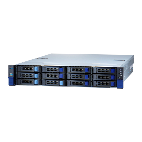
Standard Parts List This section describes TS65-B7126 package contents and accessories. Open the box carefully and ensure that all components are present and undamaged. The product should arrive with packaged as illustrated below. 1.4.1 Box Contents If any items are missing or appear damaged, contact your retailer or browse to TYAN’s website for service: http://www.tyan.com... -
Page 22: About The Product
System Front View M1718T65-FPB Front Panel Board/ M1717T65-USB USB Board LAN1 LED ID Button LAN2 LED Power Button with green LED ID LED USB3.0 Port1 Warning LED USB3.0 Port2 HDD LED (N/A, always OFF) 3.5” / 2.5” SSD/HDD/NVMe bays RESET Button http://www.tyan.com... - Page 23 Warning Red/Green/Blue PSU warning / Blue solid on FAN warning / Blue blinking System fault / Red solid on HDD present / Green solid on HDD LED Green/Red HDD activity / Green blinking HDD fail / Red solid on http://www.tyan.com...
- Page 24 Status LED (Red) Drive present, no activity Green Solid On Drive present with activity Green Blinking Drive Fail Don’t care Red Solid On Drive identify Don’t care Red Blinking @ 1Hz Drive Rebuild Don’t care Red Blinking @ 4Hz http://www.tyan.com...
-
Page 25: System Rear View
ID LED will light blue if the system is identified. Users from remote sites can also activate the ID LED by entering a few commands in IPMI. For detailed software support, please visit http://www.tyan.com for the latest AST2500 user guide. - Page 26 1Gbps LAN Port 10/100/1000 Mbps LAN Link/Activity LED Scheme Left LED Right LED Link Green 10 Mbps Active Blinking Green Link Green Green 100 Mbps Active Blinking Green Green Link Green Amber 1000 Mbps(1Gps) Active Blinking Green Amber No Link http://www.tyan.com...
-
Page 27: System Top View
(1) M7126T65-PDB Power Distribution Board (pre-installed) (1) M7063F86-PBP Power Backplane Board (pre-installed) (1+1) 1200W Power Modules (pre-installed) (1) M1298T65-BP12E-2 Rear HDD Backplane Board (pre-installed) (1) R Riser Card Bracket (M7126T65-R32-3F pre-installed) (1) L Riser Card Bracket (M7126T65-L32-3F pre-installed) (2) Air Ducts (pre-installed) http://www.tyan.com... -
Page 28: Chassis Dimension
1.5.4 Chassis Dimension http://www.tyan.com... -
Page 29: Chapter 2: Setting Up
Caution! To avoid damaging the motherboard and associated components, use torque force within the range kgf/cm (6.09 lb/in) on each mounting screw for motherboard installation. Do not apply power to the board if it has been damaged. http://www.tyan.com... -
Page 30: Precautions
Components and electronic circuit boards can be damaged by discharges of static electricity. Working on a system that is connected to a power supply can be extremely dangerous. Follow the guidelines below to avoid damage to TS65-B7126 or injury to yourself. -
Page 31: Installing Motherboard Components
CPUs, memory modules and add on cards. 2.1.1 Removing the Chassis Cover Follow these instructions to remove TS65-B7126 chassis cover. 1. Use a screw driver to loosen screws on both sides of the chassis. 2. Press the latches simultaneously and slide the chassis cover backwards. -
Page 32: Removing The Riser Bracket
2.1.2 Removing the Riser Bracket 1. Use a screwdriver to loosen two thumb screws. Then lift up the Riser Card Brackets. http://www.tyan.com... -
Page 33: Replacing The Chassis Cover
2.1.3 Replacing the Chassis Cover Follow these instructions to replace TS65-B7126 chassis cover. 1. Place the chassis cover on top. 2. Push the latches simultaneously and slide the chassis cover forwards until it clicks. 3. Use a screw driver to fasten the screws on the top cover. -
Page 34: Installing The Cpu And Heatsink
2.1.4 Installing the CPU and Heatsink Follow the steps below on installing CPU and CPU heat sink. The TS65-B7126 supports dual Intel Whitley platform for Ice-lake series CPU. The following installation is based on an Intel LGA4189 socket. 1. Take out the CPU carrier and processor. - Page 35 4. Align the triangle edge of the carrier with the notch on the edge of the heatsink. Then install the carrier on the bottom of the heatsink and make sure the latches are snapped under the edge of the heatsink. 5. Remove the CPU socket cover. http://www.tyan.com...
- Page 36 CPU socket. Then place the heatsink assembly onto the top of the CPU socket. 7. Press down on the retention clips to fix the heatsink assembly to the CPU socket. http://www.tyan.com...
- Page 37 NOTE: A new heatsink comes with pre-installed thermal grease. Once the heatsink has been removed from the processor, you need to clean the processor and heatsink using an alcohol solvent. Then apply new thermal grease before reinstalling the heatsink. http://www.tyan.com...
-
Page 38: Installing The Pci-E Card
2. Unscrew to remove the dummy bracket. 3. Insert the PCI-E card into the slot and screw it firmly to the riser card bracket. 4. Replace the riser card bracket into the chassis and use a screw driver to fasten the thumb screw. http://www.tyan.com... -
Page 39: Installing The Memory
2. Align the memory module with the slot. When inserted properly, the memory slot locking levers lock automatically onto the indentations at the ends of the module. Follow the recommended memory population table to install the other memory modules. http://www.tyan.com... - Page 40 DIMM Location http://www.tyan.com...
- Page 41 DIMM: any DIMM0 slot. DIMMs: P0_MC0_DIM_CH_A0, P0_MC2_DIM_CH_E0. P0_MC1_DIM_CH_C0, P0_MC3_DIM_CH_G0. DIMMs: P0_MC0_DIM_CH_A0, P0_MC1_DIM_CH_C0, P0_MC2_DIM_CH_E0, P0_MC3_DIM_CH_G0. P0_MC0_DIM_CH_B0, P0_MC1_DIM_CH_D0, P0_MC2_DIM_CH_F0, P0_MC3_DIM_CH_H0. DIMMs: P0_MC0_DIM_CH_A0, P0_MC0_DIM_CH_B0, P0_MC1_DIM_CH_C0, P0_MC2_DIM_CH_E0, P0_MC2_DIM_CH_F0, P0_MC3_DIM_CH_G0. P0_MC0_DIM_CH_A0, P0_MC1_DIM_CH_C0, P0_MC1_DIM_CH_D0, P0_MC2_DIM_CH_E0, P0_MC3_DIM_CH_G0, P0_MC3_DIM_CH_H0. DIMMs: P0_MC0_DIM_CH_A0, P0_MC0_DIM_CH_B0, P0_MC1_DIM_CH_C0, P0_MC1_DIM_CH_D0, P0_MC2_DIM_CH_E0, P0_MC2_DIM_CH_F0, P0_MC3_DIM_CH_G0, P0_MC3_DIM_CH_H0. http://www.tyan.com...
- Page 42 √ P0_MC2_DIM_CH_F0 √ √ P0_MC3_DIM_CH_G0 √ √ √ P0_MC3_DIM_CH_H0 √ √ √ P1_MC0_DIM_CH_A0 √ √ √ P1_MC0_DIM_CH_B0 √ √ P1_MC1_DIM_CH_C0 √ √ √ P1_MC1_DIM_CH_D0 √ √ P1_MC2_DIM_CH_E0 √ √ √ P1_MC2_DIM_CH_F0 √ √ P1_MC3_DIM_CH_G0 √ √ √ P1_MC3_DIM_CH_H0 √ http://www.tyan.com...
-
Page 43: Installing Hard Drives
2.1.7 Installing Hard Drives The TS65-B7126 supports twelve 3.5”/2.5” hot-swap HDD/SSDs and two 2.5” hot-swap HDD/SSDs at rear. Installing 3.5” Hot-Swap Hard Drives Follow these instructions to install a 3.5” HDD drive. Warning!!! Always install the hard disk drive to the chassis after the chassis has been secured on the rack. - Page 44 Pull open the locking lever to install a 3.5” hard disk drive into the HDD drive tray and lock the tray lever to secure the drive. Reinsert the HDD drive tray into the chassis. Push to secure the locking lever until it clicks into place. http://www.tyan.com...
- Page 45 Follow these instructions to install a 2.5” HDD/SSD drive. Warning!!! Always install the hard disk drive to the chassis after the chassis has been secured on the rack. Press the locking lever latch to pull the locking lever open. Slide the drive tray out. http://www.tyan.com...
- Page 46 Place the 2.5” HDD/SSD into the drive tray and align the 2.5” HDD/SSD with its guide pins. Turn over the drive tray and secure the drive to the tray using 4 screws. http://www.tyan.com...
- Page 47 Reinsert the drive tray into the chassis. Push to secure the locking lever until it clicks into place. http://www.tyan.com...
- Page 48 Press the locking lever latch to pull the locking lever open. Pull open the locking lever to install a 2.5” hard disk drive into the drive tray and lock the tray lever to secure the drive. http://www.tyan.com...
- Page 49 Reinsert the drive tray into the chassis. Push to secure the locking lever until it clicks into place. http://www.tyan.com...
-
Page 50: Rack Mounting
Rail screw Pack x 1 2.2.1 Installing the Server in a Rack Follow these instructions to mount the TYAN TS65-B7126 into an industry standard 19" rack. NOTE: Before mounting the TYAN TS65-B7126 in a rack, ensure that all internal components have been installed and that the unit has been fully tested. - Page 51 3. Repeat steps 2 to 4 to secure the sliding rail to the other side of the server. NOTE: Use a screwdriver to slightly push the latch open and then push the inner rail forwards to unlock. http://www.tyan.com...
- Page 52 1. Attach the outer rail to the rack. Pull the latch open and align the square stud with the square hole on the rack rail. Please note that the square stud must be fully attached inside the square hole and then close the latch to lock. Rear Front http://www.tyan.com...
- Page 53 http://www.tyan.com...
-
Page 54: Rack Mounting The Server
2. Slide in the chassis half way to the lock position. Push the blue tabs simultaneously to slide the chassis all in. 3. Use a screw driver to fasten the chassis ears to the front surface of chassis. http://www.tyan.com... -
Page 55: Removing The Server From Rack
2. Pull out the chassis half way to the lock position. Push the white locking tabs forwards to slide the chassis all out from the rack. Caution: Remove the server from the rack carefully. Must be done with at least 2 people. http://www.tyan.com... - Page 56 NOTE http://www.tyan.com...
-
Page 57: Chapter 3: Replacing Pre-Installed Components
Front Panel Board, M1718T65-USB Board, M1297T65-BP12E-12 HDD Backplane, M1298T65-BP12-2 Rear HDD Backplane, M7126T65-PDB Power Distribution board, M7063F86-PBP Power Backplane Board, M7126T65-R32-3F/M7126T65-L32-3F Riser cards, System fan and Power supply unit etc. 3.1.1 Disassembly Flowchart The following flowchart outlines the disassembly procedure. http://www.tyan.com... -
Page 58: Removing The Cover
3.1.2 Removing the Cover Before replacing any parts you must remove the chassis cover first. Follow Chapter 2.1.1 to remove the cover of the TS65-B7126. 3.1.3 Replacing Motherboard Components Follow these instructions to replace motherboard components, including the motherboard. Replacing the Riser Card... -
Page 59: Pci-E Riser Card Specification
PCI-E Riser Card Specification M7126T65-R32-3F Riser Card M7126T65-L32-3F Riser Card M7126T65-R32-3F / M7126T65-L32-3F Riser Card M7126T65-R32-3F: 68.47mmx131mm,T=1.6mm Form Factor M7126T65-L32-3F: 73.8mm x 132.99mm,T=1.6mm PCI-E Gen4 x16 SLOT x1 Specifications PCI-E Gen4 x8 SLOT x2 4P PWR Connector x1 http://www.tyan.com... -
Page 60: Connector Pin Definition
3.2.2 Connector Pin Definition Location Definition J1 (PCI-E#2) PCI-E X16 SLOT J2 (PCI-E#3) PCI-E X8 SLOT J3 (PCI-E#1) PCI-E X8 SLOT J4 (PWR1) 4P Power Connector http://www.tyan.com... -
Page 61: Replacing The Front Panel Board
Replacing the Front Panel Board Follow these instructions to replace the M1718T65-FPB Front Panel Board. 1. Unscrew to release the Front Panel Bezel. 2. Remove the Front Panel Bezel. http://www.tyan.com... - Page 62 3. Unscrew the Front Panel Board. 4. Disconnect the Front Panel Control Cable and replace the FPB with a new one. 5. Follow the steps described earlier in reverse to reinstall the Front Panel Board and Front Panel Bezel. http://www.tyan.com...
-
Page 63: Front Panel Board Specifications
IO: 2x15-pin Front Panel Header (J4) 3 Buttons: Reset Button (J3), ID Button (J5), Power Specifications Button with LED (J6) 6 LEDs: LAN1 LED, LAN2 LED, ID LED (LED3), Fault LED (LED6), HDD LED, Power LED http://www.tyan.com... -
Page 64: Fpb Led Definitions
Amber Solid on HDD fail Green (default) or Present & HDD_LED Blue Solid on Standby Green (default) or HDD active Blue Blinking Reset Button Reset Button ID Button ID Button Power Button Power Button Green Solid on PS-ON w/LED http://www.tyan.com... -
Page 65: Replacing The Usb Board
Replacing the USB Board Follow these instructions to replace the M1717T65-USB Front USB Board. 1. Unscrew to release the Front USB Bezel. 2. Remove the Front USB Bezel. http://www.tyan.com... - Page 66 3. Disconnect the USB cable and then unscrew the Front USB Board to replace with a new one. 4. Follow the steps described earlier in reverse to reinstall the Front USB Board and Front USB Bezel. http://www.tyan.com...
-
Page 67: Usb Board Specifications
3.4.1 USB Board Specifications M1717T65-USB USB Board Form Factor 48mmx19mm,T=1.6mm USB 3.0 Connector (J1, J2) Specifications 20-pin Header Input Connector (J3) http://www.tyan.com... -
Page 68: Replacing The System Fan
3. Use a screwdriver to press the latch and move the latch in the direction as the arrow shows to get off the fan cage. 4. Follow the steps described earlier in reverse order to replace a new fan module into the chassis. Remember to connect the fan cable. http://www.tyan.com... -
Page 69: Replacing The Hdd Backplane Board
1. Disconnect all cables connected to the M1297T65-BP12E-12 HDD Backplane. 2. Unscrew the HDD BP Board. 3. Release the HDD Backplane from the hook. 4. Follow the procedures described earlier to reinstall the HDD backplane board bracket into the chassis. http://www.tyan.com... -
Page 70: Hdd Backplane Board Features
(2) Slim SAS Connector (Oculink) Specifications (3) Mini SAS HD Connector Overview (6) 6-pin Fan Connector (2) ATX 8-pin Power Connector (1) 30-pin TYAN Fan Header Support 6 system fan (4) SGPIO Header http://www.tyan.com... -
Page 71: Connector Definition
Mini SAS HD Connector NVME01 (SLIMSAS1) SLIMSAS Connector NVME23 (SLIMSAS2) SLIMSAS Connector PW1/PW2 Power Connector J1/J2/J3/J4/J5/J6 6-pin FAN Connector 2x15pin TYAN Fan Header SGPIO0 SGPIO Header for HDD0~7 SGPIO2 SGPIO Header for HDD8~11 SGPIO3 Reserved for AMD Platform SGPIO1 Reserved... -
Page 72: Jumper Setting For Hdd Bp Led
SGPIOA decode PORT0~3, SGPIOB decode PORT 4~7, SGPIOC decode PORT 9~11 MODE_SELECT [1:0] = 10: P3280 SAS EXP mode, SGPIOA decode PORT0~11 First HDD BP MODE_SELECT [1:0] = 11: P3280 SAS EXP mode, SGPIOA decode PORT12~23 SECOND HDD BP FAN: http://www.tyan.com... -
Page 73: Replacing The Rear Hdd Bp Board
1. Disconnect the Micro-fit 4pin power cable and SATA cable. Use a screwdriver to loosen the thumb screw to remove the Rear HDD BP Board. Follow the procedures described earlier in reverse order to reinstall a new Rear HDD BP Board. http://www.tyan.com... -
Page 74: Rear Hdd Bp Board Features
Rear HDD BP Board Features Front View Rear View M1298T65-BP12-2 HDD Backplane Board Form Factor 33.5mmx76mm,T=3mm (2) 2.5” NVMe SSD/SATA (SATA 6Gb/s or SAS 12Gb/s) Integrated I/O (1) SLIMSAS Connector (1) 4pin Power Connector (2) SATA 7pin Connector http://www.tyan.com... -
Page 75: Hdd Led Definition
3.7.2 HDD LED Definition Definition Location SLIMSAS Connector NVME0 SATA + NVMe Connector NVME1 SATA + NVMe Connector SATA0 SATA Connector SATA1 SATA Connector 4P Power Connector 3PHD1 Header for PCA9544 SMBUS address Select http://www.tyan.com... -
Page 76: Replacing The Power Distribution Board
1. Disconnect all cables connected to the power distribution board. 2. Unscrew to take off the power distribution board and replace with a new one. 3. Insert the PDB into the chassis following the above procedures in reverse order. http://www.tyan.com... -
Page 77: Power Distribution Board Features
(1) ATX 24-pin power connector (1) ATX 20-pin power connector (3) ATX 8-pin power connector Integrated I/O (1) ATX 4-pin power connector (2) HDD 4P power connector (1) DOM 5V power connector (1) PMBUS connector http://www.tyan.com... -
Page 78: Connector Pin Definition
3.8.2 Connector Pin Definition Location Definition PWR1 ATX Power 12x2 ATX Power 10x2 ATX Power 4x2 ATX Power 4x2 ATX Power 4x2 ATX Power 2x2 HDD Power 4x1 HDD Power 4x1 PMBUS DOM_5V_PW1 DOM Power http://www.tyan.com... -
Page 79: Replacing The Power Backplane Board
1. Unscrew to remove the bracket from the PBP tray. 2. Unscrew to lift up the PDB. Then push the PBP tray backwards. 3. Push the PBP tray in the direction as the arrow shows to unlock the PBP tray. http://www.tyan.com... - Page 80 4. Lift up the PBP tray. 4. Unscrew to replace with a new power backplane board. 5. Follow the steps described earlier in reverse order to reinstall the power backplane board tray into the chassis. http://www.tyan.com...
-
Page 81: Power Backplane Board Features
M7063F86-PBP Power Backplane Board Board Size 70MMx 65MM,T=1.6mm Support (2) Standard RPSU (2) FCI golden-finger power connector for Delta Integrated I/O redundant PSU (J1, J3) (1) FCI golden-finger power connector for M7126T65-PDB (J2) 3.10 Replacing the Power Supply http://www.tyan.com... - Page 82 Follow these instructions to replace the power supply module in your system. Press the latch to pull the power supply out. After replacing a new power supply, press and hold the latch to push the power supply back into the chassis. http://www.tyan.com...
-
Page 83: Replacing The Motherboard
Follow the instructions below to replace the motherboard from the chassis. 1. Remove all components installed on the mainboard if there are any. 2. Disconnect all cables connected to the motherboard. 3. Remove nine screws securing the motherboard to the chassis. 4. Carefully lift the motherboard from the chassis. http://www.tyan.com... - Page 84 NOTE http://www.tyan.com...
-
Page 85: Chapter 4: Mainboard Information
To avoid damaging the motherboard and associated components, do not use torque force greater than kgf/cm (4.35 ~ 6.09 lb/in) on each mounting screw for motherboard installation. Do not apply power to the board if it has been damaged. http://www.tyan.com... -
Page 86: Board Image
Board Image S7126 This picture is representative of the latest board revision available at the time of publishing. The board you receive may not look exactly like the above picture. http://www.tyan.com... -
Page 87: Block Diagram
Block Diagram S7126 Block Diagram http://www.tyan.com... -
Page 88: Mainboard Mechanical Drawing
Mainboard Mechanical Drawing http://www.tyan.com... -
Page 89: Board Parts, Jumpers And Connectors
The board you receive may not look exactly like the above diagram. But for the DIMM number please refer to the above placement for memory installation. For the latest board revision, please visit our web site at http://www.tyan.com. http://www.tyan.com... - Page 90 6 I210 LAN connector (LAN1) 24 FPB USB2.0/3.0x2 (USB3_FPIO1) 7 Vertical Type-A USB connector 25 Rear IO_FAN1 (SYS_FAN_4) (TYPEA_USB3) 8 TYAN Module Hader (DBG_HD1) 26 Rear IO_FAN2 (SYS_FAN_3) 27 SSI 8-pin CPU1 Power connector 9 M.2 22x80mm connector (NGFF1) (PW2)
- Page 91 Memory Error LED-CPU0 (LED60) XIII Memory Error LED-CPU1 (LED71) XXVIII PSU_ALERT_N LED (PSMI_LED1) XXIX Platform RESET LED Memory Error LED-CPU1 (LED74) (SYS_RST_LED1) Memory Error LED-CPU1 (LED73) Jumper Legend OPEN - Jumper OFF Without jumper cover CLOSED - Jumper ON With jumper cover http://www.tyan.com...
- Page 92 FP_ PWER FP_PW_LED_PW (VCC3_Aux) FP_ID_LED_PW FP_PW_LED_GND FP_ID_LED_N HDD_LED_PW BMC_HW_FAULT_N HDD_ACT_LED_N BMC_SYS_FAULT_N FP_PWR_BTN_N LAN0_LED_P LAN0_LED_N FP_RST_BTN_JP_N FP_SMB_DAT FP_SMB_CLK FP_IDLED_BTN_N FP_INTRUSION_N SYS_AIR_INLET LAN1_LED_P FP_NMI_BTN_N LAN1_LED_N PSMI_HD1: PSMI Connector Signal SMB_CLK SMB_DAT PSU_SMBALERT_N V3.3 IPMB_HD1: 4-pin IPMB Connector Signal IPMB_DAT IPMB_CLK VCC3_AUX http://www.tyan.com...
- Page 93 DBG_HD1: TYAN Module Header Signal Signal VCC3 FRAME_N LAD0 LAD1 PLT_RST_N LAD2 LAD3 CLK_33M DBG_SERIRQ DBG_PRES_N VCC3_AUX TPM_ADDR_MB PCH_TPM_PP_EN FAN_HD1: Fan Connector (Reserved for Barebone) Signal Signal TACH1 TACH6 TACH2 TACH7 TACH3 TACH8 TACH4 TACH9 TACH5 TACH10 PWM2 PWM1 TACH11...
- Page 94 COM2_DSR COM2_RXD COM2_RTS COM2_TXD COM2_CTS COM2_DTR COM2_NRI ® J51: Intel VROC RAID KEY Connector (NVMe only) Signal Signal 2.21K to VCC3_AUX 2.21K to VCC3_AUX HDR_3: 7-pin NVMe Hot Plug Function Connector Signal Signal VCC3_AUX HP0_SCK HP0_SDA CPU01_SMBALERT_N_C HP1_SCK HP1_SDA http://www.tyan.com...
- Page 95 SSATA4_TXP_C Connects to the Serial SSATA4_TXN_C ATA ready drives via the Serial ATA cable. SSATA4_RXN_C SSATA4_RXP_C sSATA5: 7-pin Vertical SATA Connector PIN Define SSATA5_TXP_C Connects to the Serial SSATA5_TXN_C ATA ready drives via the Serial ATA cable. SSATA5_RXN_C SSATA5_RXP_C http://www.tyan.com...
- Page 96 After flashing new BIOS, do the following steps: a. Clear CMOS b. Enter BIOS setup menu and load Default Settings. Then do a Save and Exit from setup. J114: Security Override Header (reserved) Signal BMC_ME_OVERRIDE_N 3PHD8: SMBUS Select Header (reserved) Signal CPU#_BMC_SMB_SEL http://www.tyan.com...
- Page 97 NGFF1: M.2 Connector Signal Signal VCC3 VCC3 VCC3_AUX M2_LED_N VCC3 VCC3 VCC3 VCC3 PCH_PE1_M2_1_RX_N P12V_IN P12V_IN PCH_PE1_M2_1_RX_P P12V_IN P12V_IN PCH_PE1_M2_1_TX_N PCH_PE1_M2_1_TX_P M2_SMB_CLK_R PCH_PE0_M2_0_RX_N M2_SMB_DAT_R PCH_PE0_M2_0_RX_P PCH_PE0_M2_0_TX_N M2_PERST_N_R PCH_PE0_M2_0_TX_P M2_2_PEWAKE_N CLK_100M_M2_DN CLK_100M_M2_DP PE_M.2_DETECT_N VCC3 VCC3 VCC3 http://www.tyan.com...
- Page 98 PCH_SSATA_0_3: 36-pin Vertical Mini SAS Connector (SATA 3.0 signals) Signal Signal PCH_SSATA_0-3_A1 SGPIO_SSATA_CLK SGPIO_SSATA_LOAD SSATA1_RXP_C SSATA0_RXP_C SSATA1_RXN_C SSATA0_RXN_C SSATA3_RXP_C SSATA2_RXP_C SSATA3_RXN_C SSATA2_RXN_C SSGPIO_DO_0R SSGPIO_DI_0R SAS1_CTYPE SSATA1_TXP_C SSATA0_TXP_C SSATA1_TXN_C SSATA0_TXN_C SSATA3_TXP_C SSATA2_TXP_C SSATA3_TXN_C SSATA2_TXN_C http://www.tyan.com...
- Page 99 SATA1_RXN_C SATA0_RXN_C SATA3_RXP_C SATA2_RXP_C SATA3_RXN_C SATA2_RXN_C SGPIO_DO_0R SGPIO_DI_0R SAS0_CTYPE SATA1_TXP_C SATA0_TXP_C SATA1_TXN_C SATA0_TXN_C SATA3_TXP_C SATA2_TXP_C SATA3_TXN_C SATA2_TXN_C NC_PCH_SATA_0-7_A10 SGPIO_SATA_CLK SGPIO_SATA_LOAD SATA5_RXP_C SATA4_RXP_C SATA5_RXN_C SATA4_RXN_C SATA7_RXP_C SATA6_RXP_C SATA7_RXN_C SAA6_RXN_C SGPIO_DO_1R SGPIO_DI_1R SAS1_CTYPE SATA5_TXP_C SATA4_TXP_C SATA5_TXN_C SATA4_TXN_C SATA7_TXP_C SATA6_TXP_C SATA7_TXN_C SATA6_TXN_C http://www.tyan.com...
- Page 100 CPU1_PE2_ABCD_RX_DP2 CPU1_PE2_ABCD_TX_DN2_C CPU1_PE2_ABCD_RX_DN3 CPU1_PE2_ABCD_TX_DP3_C CPU1_PE2_ABCD_RX_DP3 CPU1_PE2_ABCD_TX_DN3_C SlimSAS2: Vertical Slim SAS Connector Signal Name Signal Name CPU1_PE2_ABCD_RX_DN4 CPU1_PE2_ABCD_TX_DP4_C CPU1_PE2_ABCD_RX_DP4 CPU1_PE2_ABCD_TX_DN4_C CPU1_PE2_ABCD_RX_DN5 CPU1_PE2_ABCD_TX_DP5_C CPU1_PE2_ABCD_RX_DP5 CPU1_PE2_ABCD_TX_DN5_C BP_TYPEB PE_HD1_SMB_CLK PE_WAKE_N1 PE_HD1_SMB_DAT SLIMSAS_NVME1_DP PCIE_SLIMSAS_RST_N SLIMSAS_NVME1_DN CPRSNTA- CPU1_PE2_ABCD_RX_DN6 CPU1_PE2_ABCD_TX_DP6_C CPU1_PE2_ABCD_RX_DP6 CPU1_PE2_ABCD_TX_DN6_C CPU1_PE2_ABCD_RX_DN7 CPU1_PE2_ABCD_TX_DP7_C CPU1_PE2_ABCD_RX_DP7 CPU1_PE2_ABCD_TX_DN7_C http://www.tyan.com...
- Page 101 CPU1_PE2_ABCD_RX_DP10 CPU1_PE2_ABCD_TX_DN10_C CPU1_PE2_ABCD_RX_DN11 CPU1_PE2_ABCD_TX_DP11_C CPU1_PE2_ABCD_RX_DP11 CPU1_PE2_ABCD_TX_DN11_C SlimSAS4: Vertical Slim SAS Connector Signal Name Signal Name CPU1_PE2_ABCD_RX_DN12 CPU1_PE2_ABCD_TX_DP12_C CPU1_PE2_ABCD_RX_DP12 CPU1_PE2_ABCD_TX_DN12_C CPU1_PE2_ABCD_RX_DN13 CPU1_PE2_ABCD_TX_DP13_C CPU1_PE2_ABCD_RX_DP13 CPU1_PE2_ABCD_TX_DN13_C BP_TYPED PE_HD3_SMB_CLK PE_WAKE_N3 PE_HD3_SMB_DAT SLIMSAS_NVME3_DP PCIE_SLIMSAS_RST_N SLIMSAS_NVME3_DN CPRSNTA- CPU1_PE2_ABCD_RX_DN14 CPU1_PE2_ABCD_TX_DP14_C CPU1_PE2_ABCD_RX_DP14 CPU1_PE2_ABCD_TX_DN14_C CPU1_PE2_ABCD_RX_DN15 CPU1_PE2_ABCD_TX_DP15_C CPU1_PE2_ABCD_RX_DP15 CPU1_PE2_ABCD_TX_DN15_C http://www.tyan.com...
- Page 102 J113: ME Recovery Jumper Signal Signal FM_ME_RCVR_N 1K-Pull down Pin1-2 closed: Normal Mode (Default) Pin2-3 closed: ME In Force Update Mode J136: System Reset Jumper Signal Signal FP_RST_BTN_N FP_RST_BTN_JP_N FP_BMC_RST_BTN_N Pin1-2 closed: System Reset (Default) Pin2-3 closed: BMC Reset http://www.tyan.com...
- Page 103 1KK to VCC3_AUX 10K to GND Pin1-2 closed: PP-PECI to BMC (Default) Pin1-2 open: NI-PECI to PCH J120: System Buzzer Jumper VCC5_BZ BUZ_1 BUZ_2 Pin3-4 closed: Normal Mode (Default) Pin2-3 closed: Disable PC Beep Pin1-4 closed: Use the external speaker http://www.tyan.com...
-
Page 104: Led Definitions
The LED blinks per second to Blinking Green indicate that the BMC controller is working normally Signal + VCC3 CPU0 P0_PG_LED1 PWOK State Description The LED shuts off when the power of CPU0 is abnormal. Green The LED lights up when the http://www.tyan.com... - Page 105 + VCC3_SB DIMM Error LED59 ~ LED74 State Description The DIMM status is normal The DIMM status is abnormal. Signal + VCC3_AUX HW Sensor IPMI_LED1 Alert LED State Description HW Sensor status is normal HW Sensor status is abnormal. http://www.tyan.com...
-
Page 106: Installing The Processor And Heat Sink
Check our website at http://www.tyan.com for latest processor support. NOTE: MITAC TYAN is not liable for damage as a result of operating an unsupported configuration. Processor Installation for Intel LGA4189 Socket Follow the steps below to install the processors and heat sinks. - Page 107 4. Carefully flip the heatsink assembly. Align the heatsink with the CPU socket by the guide pins. Make also sure that the triangle edge of the carrier is aligned correctly with the triangle mark on the CPU socket. Then place the heatsink assembly onto the top of the CPU socket. http://www.tyan.com...
- Page 108 When disassembling the heatsink, loosen the screws in reverse order (4321). NOTE: Always check with the manufacturer of the heat sink & processor to ensure that the thermal interface material is compatible with the processor and meets the manufacturer’s warranty requirements. http://www.tyan.com...
-
Page 109: Tips On Installing Motherboard In Chassis
Some chassis include plastic studs instead of metal. Although the plastic studs are usable, MITAC recommends using metal studs with screws that will fasten the motherboard more securely in place. Below is a chart detailing what the most common motherboard studs look like and how they should be installed. http://www.tyan.com... - Page 110 http://www.tyan.com...
-
Page 111: Installing The Memory
Installing the Memory Before installing memory, ensure that the memory you have is compatible with the motherboard and processor. Check the TYAN Web site at http://www.tyan.com details of the type of memory recommended for your motherboard. DDR4/DDR-T Memory Population Guidelines The Whitley Ice Lake processor has up to eight channel memory interfaces ®... - Page 112 Intel. If DIMMs with different frequencies are mixed in the same channel, all DIMMs will run at the highest common frequency. NVDIMM, if supported can not be mixed with PMem module. http://www.tyan.com...
- Page 113 DIMM0 followed by DIMM1 Channel 0’s on each memory controller (A/E/C/G) must be populated with same total capacity per channel (if populated) Channel 1’s on each memory controller (B/F/D/H) must be populated with same total capacity per channel (if populated) http://www.tyan.com...
- Page 114 DIMM0 followed by DIMM1 Ice Lake Channel 0’s on each memory controller (A/E/C/G) must be populated with same total capacity per channel (if populated) Ice Lake Channel 1’s on each memory controller (B/F/D/H) must be populated with same total capacity per channel (if populated) http://www.tyan.com...
- Page 115 “fill-farthest” approach. Always populate DIMMs with the maximum number of ranks in the farthest DIMM slot, followed by the nearest DIMM slot. Lastly, always populated DDR4 in the farthest DIMM ® slot, then populate the Intel Optane PMem in the nearest DIMM slot. http://www.tyan.com...
- Page 116 DIMM Location http://www.tyan.com...
- Page 117 DIMM: any DIMM0 slot. DIMMs: P0_MC0_DIM_CH_A0, P0_MC2_DIM_CH_E0. P0_MC1_DIM_CH_C0, P0_MC3_DIM_CH_G0. DIMMs: P0_MC0_DIM_CH_A0, P0_MC1_DIM_CH_C0, P0_MC2_DIM_CH_E0, P0_MC3_DIM_CH_G0. P0_MC0_DIM_CH_B0, P0_MC1_DIM_CH_D0, P0_MC2_DIM_CH_F0, P0_MC3_DIM_CH_H0. DIMMs: P0_MC0_DIM_CH_A0, P0_MC0_DIM_CH_B0, P0_MC1_DIM_CH_C0, P0_MC2_DIM_CH_E0, P0_MC2_DIM_CH_F0, P0_MC3_DIM_CH_G0. P0_MC0_DIM_CH_A0, P0_MC1_DIM_CH_C0, P0_MC1_DIM_CH_D0, P0_MC2_DIM_CH_E0, P0_MC3_DIM_CH_G0, P0_MC3_DIM_CH_H0. DIMMs: P0_MC0_DIM_CH_A0, P0_MC0_DIM_CH_B0, P0_MC1_DIM_CH_C0, P0_MC1_DIM_CH_D0, P0_MC2_DIM_CH_E0, P0_MC2_DIM_CH_F0, P0_MC3_DIM_CH_G0, P0_MC3_DIM_CH_H0. http://www.tyan.com...
- Page 118 √ P0_MC2_DIM_CH_F0 √ √ P0_MC3_DIM_CH_G0 √ √ √ P0_MC3_DIM_CH_H0 √ √ √ P1_MC0_DIM_CH_A0 √ √ √ P1_MC0_DIM_CH_B0 √ √ P1_MC1_DIM_CH_C0 √ √ √ P1_MC1_DIM_CH_D0 √ √ P1_MC2_DIM_CH_E0 √ √ √ P1_MC2_DIM_CH_F0 √ √ P1_MC3_DIM_CH_G0 √ √ √ P1_MC3_DIM_CH_H0 √ http://www.tyan.com...
- Page 119 Follow these instructions to install memory modules into the S7126. Unlock the clips as shown in the illustration. Insert the memory module firmly into the socket by gently pressing down until it sits flush with the socket. Lock the clips to secure the memory module into place. http://www.tyan.com...
-
Page 120: Attaching Drive Cables
If you are in need of SATA/SAS cables or power adapters please contact your place of purchase. The following pictures illustrate how to connect an SATA drive. 1. SATA drive cable connection 2. SATA drive power connection 3. SATA cable motherboard connector 4. SATA drive power adapter http://www.tyan.com... -
Page 121: Installing Add-In Cards
Doing so allows air to circulate within the chassis more easily, thus improving cooling for all installed devices. NOTE: You must always unplug the power connector to the motherboard before performing system hardware changes to avoid damaging the board or expansion device. http://www.tyan.com... -
Page 122: Connecting External Devices
Right LED No Link Link Green 10Mbps Active Blinking Green Solid Green Link Green 100Mbps Solid Green Active Blinking Green Solid Yellow Link Green 1Gbps Solid Yellow Active Blinking Green Link Green Solid Yellow 10Gbps Solid Yellow Active Blinking Green http://www.tyan.com... -
Page 123: Installing The Power Supply
VCC5 P12V_IN VCC5 VCC3 PW1: 8-PIN Power Connector Signal Signal VCC12_P0 VCC12_P0 VCC12_P0 VCC12_P0 PW2: 8-PIN Power Connector Signal Signal VCC12_P1 VCC12_P1 VCC12_P1 VCC12_P1 NOTE: You must unplug the power supply before plugging the power cables to motherboard connectors. http://www.tyan.com... -
Page 124: Finishing Up
In the rare circumstance that you have experienced difficulty, you can find help by asking your vendor for assistance. If they are not available for assistance, please find setup information and documentation online at our website or by calling your vendor’s support line. http://www.tyan.com... -
Page 125: Chapter 5: Bios Setup
The table below shows how to navigate in the setup program using the keyboard. Function Left/Right Arrow Keys Change from one menu to the next Up/Down Arrow Keys Move between selections Enter Open highlighted section PgUp/PgDn Keys Change pages Change options Exit http://www.tyan.com... -
Page 126: Getting Help
The following pages provide the details of BIOS menu. Please be noticed that the BIOS menu are continually changing due to the BIOS updating. The BIOS menu provided are the most updated ones when this manual is written. Please visit TYAN’s website at http://www.tyan.com for the information of BIOS updating. -
Page 127: Main Menu
English / Simplified Chinese / Japanese System Date Set the Date. Use Tab to switch between Date elements. Default Ranges: Year: 1998-9999 Months: 1-12 Days: dependent on month System Time Set the Time. Use Tab to switch between Time elements. http://www.tyan.com... -
Page 128: Advanced Menu
Option ROM Dispatch Policy Option ROM Dispatch Policy. S5 RTC Wake Settings Enable system to wake from S5 using RTC alarm. Trusted Computing Trusted Computing Settings. ACPI Settings System ACPI Parameters. AST2500 Super IO Configuration System Super IO Chip Parameters. http://www.tyan.com... - Page 129 Press <Enter> to view or change the runtime error log configuration. USB Configuration USB Configuration Parameters. NVMe Configuration NVMe Device Options Settings. Onboard Device Configuration Onboard Device and Function Configuration. Redfish Host Interface Settings Redfish Host Interface Parameters. Network Stack Configuration Network Stack Settings. http://www.tyan.com...
- Page 130 MAC: XXXXXXXXXXXX --- IPV4 Network Configuration Configure network parameters. (MAC: XXXXXXXXXXXX) MAC: XXXXXXXXXXXX --- IPV6 Network Configuration Configure IPV6 network parameters. (MAC: XXXXXXXXXXXX) Intel® I210 Gigabit Network Connection – XX:XX:XX:XX:XX:XX Configure Gigabit Ethernet device parameters. VLAN Configuration (MAC: XXXXXXXXXXXX) VLAN Configuration (MAC: XXXXXXXXXXXX) http://www.tyan.com...
- Page 131 Configure network parameters. (MAC: XXXXXXXXXXXX) MAC: XXXXXXXXXXXX --- IPV6 Network Configuration Configure IPV6 network parameters. (MAC: XXXXXXXXXXXX) Intel® Virtual RAID on CPU This formset allows the user to manage Intel® Virtual RAID on CPU Driver Health Provides Health Status for the Drivers/Controllers. http://www.tyan.com...
-
Page 132: Option Rom Dispatch Policy
@ s0/[Bx2/Dx0/Fx0] Enabled / Disabled On Board LAN2 (I210) Onboard Device has: UEFI [X]. Legacy [ ] Embedded ROM(s). VIDx8086;DIDx1533 @ s0/[Bx3/Dx0/Fx0] Enabled / Disabled Slot #1~10 Empty Enable or Disable Option ROM execution for selected Slot. Enabled / Disabled http://www.tyan.com... -
Page 133: S5 Rtc Wake Settings
Select 0-23. For example enter 3 for 3am and 15 for 3pm. Wake up minute Select 0-59 for Minute. Wake up second Select 0-59 for Second. When Wake system from S5 is set to [Dynamic Time] Wake up Minute increase 1-5. http://www.tyan.com... -
Page 134: Trusted Computing
5.3.3 Trusted Computing Security Device Support Enables or Disables BIOS support for security device. O.S. will not show Security Device. TCG EFI protocol and INT1A interface will not be available. Enabled / Disabled http://www.tyan.com... -
Page 135: Acpi Settings
Enable ACPI Auto Configuration Enable or Disable BIOS ACPI Auto Configuration. Disabled / Enabled Enable Hibernation Enable or Disable System ability to Hibernate (OS/S4 Sleep State). This option may not be effective with some operating system. Disabled / Enabled http://www.tyan.com... -
Page 136: Ast2500 Super Io Configuration
5.3.5 AST2500 Super IO Configuration Super IO Chip Read only. Serial Port 1 Configuration Set Parameters of Serial Port 1 (COMA). Serial Port 2 Configuration Set Parameters of Serial Port 2 (COMB). http://www.tyan.com... - Page 137 / IO=3F8h, IRQ=3, 4, 5, 6, 7, 9, 10, 11, 12; / IO=2F8h; IRQ=3, 4, 5, 6, 7, 9, 10, 11, 12; / IO=3E8h, IRQ=3, 4, 5, 6, 7, 9, 10, 11, 12; / IO=2E8h, IRQ=3, 4, 5, 6, 7, 9, 10, 11, 12; http://www.tyan.com...
- Page 138 / IO=3F8h, IRQ=3, 4, 5, 6, 7, 9, 10, 11, 12; / IO=2F8h; IRQ=3, 4, 5, 6, 7, 9, 10, 11, 12; / IO=3E8h, IRQ=3, 4, 5, 6, 7, 9, 10, 11, 12; / IO=2E8h, IRQ=3, 4, 5, 6, 7, 9, 10, 11, 12; http://www.tyan.com...
-
Page 139: Power Management
5.3.6 Power Management CPU Power and Performance Policy CPU Power and Performance Policy. Performance / Balanced Power / Power http://www.tyan.com... -
Page 140: Serial Port Console Redirection
Console redirection enable or disable. Disabled / Enabled Legacy Console Redirection Settings Legacy Console redirection settings. Console Redirection Settings The settings specify how the host computer (which the user is using) will exchange data. Both computers should have the same or compatible settings. http://www.tyan.com... - Page 141 0 if the num of 1’s in the data bits is even. Odd: parity bit is 0 if the num of 1’s in the data bits is odd. Mark: parity bit is always 1. Space: parity bit is always 0. Mark and Space parity do not allow for error detection. None / Even / Odd / Mark / Space http://www.tyan.com...
- Page 142 On this mode enabled only text will be sent. This is to capture Terminal data. Disabled / Enabled Resolution 100x31 Enable or disable extended terminal resolution. Disabled / Enabled Putty KeyPad Select FunctionKey and KeyPad on Putty. VT100 / LINUX / XTERMR6 / SCO / ESCN / VT400 http://www.tyan.com...
- Page 143 0 if the num of 1’s in the data bits is even. Odd: parity bit is 0 if the num of 1’s in the data bits is odd. Mark: parity bit is always 1. Space: parity bit is always 0. Mark and Space parity do not allow for error detection. None / Even / Odd / Mark / Space http://www.tyan.com...
- Page 144 On this mode enabled only text will be sent. This is to capture Terminal data. Disabled / Enabled Resolution 100x31 Enable or disable extended terminal resolution. Disabled / Enabled Putty KeyPad Select FunctionKey and KeyPad on Putty. VT100 / LINUX / XTERMR6 / SCO / ESCN / VT400 http://www.tyan.com...
- Page 145 When BootLoader is selected, then Legacy Console Redirection is disabled before booting to legacy OS, When Always Enable is selected, then Legacy Console Redirection is enabled for legacy OS. Default setting for this option is set to Always Enable. Always Enable / BootLoader http://www.tyan.com...
- Page 146 VT-UTF8 / VT100 / VT100+ / ANSI Bits per Second Select serial port transmission speed. The speed must be matched on the other side. Long or noisy lines may require lower speeds. 115200 / 9600 / 19200 / 57600 http://www.tyan.com...
- Page 147 ‘start’ signal can be sent to restart the flow. Hardware flow control uses two wires to send start/stop signal. None / Hardware RTS/CTS / Software Xon/Xoff Data Bits / Parity / Stop Bits Read only. http://www.tyan.com...
-
Page 148: Pci Subsystem Settings
Enables or Disables 64bit capable Devices to be Decoded in Above 4G Address Space (Only if System Supports 64 bit PCI Decoding). Enabled / Disabled SR-IOV Support If system has SR-IOV capable PCIe Devices, this option Enables or Disables Single Root IO Virtualization Support. Enabled / Disabled http://www.tyan.com... -
Page 149: Socket Configuration
Displays and provides option to change the Uncore Settings. Memory Configuration Displays and provides option to change the Memory Settings. IIO Configuration Displays and provides option to change the IIO Settings. Advanced Power Management Configuration Displays and provides option to change the Power Management Settings. http://www.tyan.com... - Page 150 Note: A change to this option requires the system to be powered off and then back on before the setting takes effect. Disabled / Enabled Enable SMX Enables Safer Mode Extensions. Disabled / Enabled http://www.tyan.com...
- Page 151 5.3.9.1.1 Per-Socket Configuration CPU Socket 0 Configuration CPU Socket 0 Configuration. CPU Socket 1 Configuration CPU Socket 1 Configuration. http://www.tyan.com...
- Page 152 5.3.9.1.1.1 CPU Socket 0 Configuration Core Disable Bitmap (Hex) 0: Enable all cores. FFFFFFFFFF: Disable all cores. NOTE: At least one core per CPU must be enabled. Disabling all cores is an invalid configuration. http://www.tyan.com...
- Page 153 5.3.9.1.1.2 CPU Socket 1 Configuration Core Disable Bitmap (Hex) 0: Enable all cores. FFFFFFFFFF: Disable all cores. NOTE: At least one core per CPU must be enabled. Disabling all cores is an invalid configuration. http://www.tyan.com...
- Page 154 Selects the allocation size used to assign mmioh resources. Total mmioh space can be up to 32xgranularity. Per stack mmioh resource assignments are multiples of the granularity where 1 unit per stack is the default allocation. 1G / 4G / 16G / 64G / 256G / 1024G http://www.tyan.com...
- Page 155 Numa Enable or Disable Non uniform Memory Access (NUMA). Disabled / Enabled http://www.tyan.com...
- Page 156 5.3.9.3 UPI Configuration UPI General Configuration Displays and provides option to change the UPI General Settings. http://www.tyan.com...
- Page 157 Disable --- Reset it, Auto --- Auto decides based on Si Compatibility. Disabled / Enable / Auto Link L1 Enable Enable --- Set the c_l1_en, Disable --- Reset it, Auto --- Auto decides based on Si Compatibility. Disabled / Enable / Auto http://www.tyan.com...
- Page 158 SNC disable will support 1-cluster (XPT/KTI Prefetch enable) 4-IMC may interleave. SNC2 Enable supports 2-clusters SNC and 2-way IMC interleave. SNC4 Enable supports 4-clusters SNC and 1-way IMC interleave. Enable SNC2 or SNC4 will gray out IMC-interleave knob and UmaBasedClustering knob. Disabled / Enable SNC2 (2-clusters) http://www.tyan.com...
- Page 159 5.3.9.3.1.1 UPI Status Read only http://www.tyan.com...
- Page 160 (limited by processor support). Do not select Reserved. Auto / 2400 / 2666 / 2933 / 3200 Erase-Arm NVDIMMs Enables/Disables Erasing and Arming NVDIMMs. Enabled / Disabled Restore NVDIMMs Enables/Disables automatic resotring of NVDIMMs. Enabled / Disabled http://www.tyan.com...
- Page 161 Interleave NVDIMMs Controls if NVDIMMs are interleaved together or not. Enabled / Disabled http://www.tyan.com...
- Page 162 Disabled / Full Mirror Mode / Partial Mirror Mode Mirror TAD0 Enable Mirror on entire memory for TAD0. Enabled / Disabled Correctable Error Threshold Correctable Error Threshold (0x01 – 0x7fff) used for sparing, tagging, and leaky bucket. Patrol Scrub Enable/Disable Patrol Scrub. Disabled / Enabled http://www.tyan.com...
- Page 163 Enable/Disable PCIe ACPI Hot Plug globally, or allow per-port control. When Disabled, MSI is generated on HP event. When enabled, _HPGPE message is generated. Disabled / Enable / Per individual port PCIe Low Latency Retimers Enable/Disable PCIe low latency retimers. Disabled / Enable http://www.tyan.com...
- Page 164 Skip PCIe retimers detection Skip PCIe retimers detection to speedup the boot. Retimers are present only in specific HW configurations. Disabled / Enable http://www.tyan.com...
- Page 165 Selects PCIe port Bifurcation for selected slot(s). x4x4x4x4 / x4x4x8 / x8x4x4 / x8x8 / x16 NOTE: The default setting is x16 for MB, x8x8 for TS65-B7126. IOU3 (IIO PCIe Port 4) Selects PCIe port Bifurcation for selected slot(s). x4x4x4x4 / x4x4x8 / x8x4x4 / x8x8 / x16 IOU4 (IIO PCIe Port 5) Selects PCIe port Bifurcation for selected slot(s).
- Page 166 This option specifies if the link is considered Hot Plug capable. Disabled / Enabled Link Speed Choose Link Speed for this PCIe port. Auto / Gen1 (2.5 GT/s) / Gen2 (5 GT/s) / Gen3 (8 GT/s) / Gen4 (16 GT/s) http://www.tyan.com...
- Page 167 128B / 256B / 512B / Auto PCI-E ASPM Support This option enables/disables the ASPM (L1) support for the downstream devices. Auto / L1 Only / L0s only / Disabled Hide Port? User can force to hide this root port from OS. Disabled / Enabled http://www.tyan.com...
- Page 168 Selects PCIe port Bifurcation for selected slot(s). x4x4x4x4 / x4x4x8 / x8x4x4 / x8x8 / x16 NOTE: The default setting is x16 for MB, x8x8 for TS65-B7126. IOU3 (IIO PCIe Port 4) Selects PCIe port Bifurcation for selected slot(s). x4x4x4x4 / x4x4x8 / x8x4x4 / x8x8 / x16 NOTE: The default setting is x4x4x4x4, for onboard 4x SLIMSAS ports.
- Page 169 Auto / Gen1 (2.5 GT/s) / Gen2 (5 GT/s) / Gen3 (8 GT/s) / Gen4 (16 GT/s) Override Max Link Width Override the max link width that was set by bifurcation. Auto / x1 / x2 / x4 / x8 / x16 http://www.tyan.com...
- Page 170 128B / 256B / 512B / Auto PCI-E ASPM Support This option enables/disables the ASPM (L1) support for the downstream devices. Auto / L1 Only / L0s only / Disabled Hide Port? User can force to hide this root port from OS. Disabled / Enabled http://www.tyan.com...
- Page 171 5.3.9.5.3 Intel® VT for Directed I/O (VT-d) Intel® VT for Directed I/O (VT-d) Enable/Disable Intel® Virtualization Technology for Directed I/O (VT-d) by reporting the I/O device assignment to VMM through DMAR ACPI Tables. Enabled / Disabled http://www.tyan.com...
- Page 172 5.3.9.5.4 Intel® VMD Technology http://www.tyan.com...
- Page 173 Disabled / Enabled VMD Config for IOU1 Enable/Disable VMD in this Stack. Disabled / Enabled VMD Config for IOU2 Enable/Disable VMD in this Stack. Disabled / Enabled VMD Config for IOU3 Enable/Disable VMD in this Stack. Disabled / Enabled http://www.tyan.com...
- Page 174 VMD Config for IOU4 Enable/Disable VMD in this Stack. Disabled / Enabled http://www.tyan.com...
- Page 175 Disabled / Enabled VMD Config for IOU1 Enable/Disable VMD Enable/Disable VMD in this Stack. Disabled / Enabled VMD Config for IOU2 Enable/Disable VMD Read only. VMD Config for IOU3 Enable/Disable VMD Enable/Disable VMD in this Stack. Disabled / Enabled http://www.tyan.com...
- Page 176 32-bit non-prefetchable / 64-bit prefetchable / 64-bit prefetchable MemBar1 size Setup VMD Memory BAR1 size (in bits Min=20), ex: 20bits=1MB, 22bits=4MB, 26bits=64MB. MemBar1 attribute Set up VMD Memory BAR1 attribute, like 64-bit or prefetchable. 32-bit non-prefetchable / 64-bit non-prefetchable / 64-bit prefetchable http://www.tyan.com...
- Page 177 Set up VMD Memory BAR2 attribute, like 64-bit or prefetchable. 32-bit non-prefetchable / 64-bit non-prefetchable / 64-bit prefetchable VMD for Direct Assign Enable/Disable VMD for Direct Assign. Disabled / Enabled VMD Config for IOU4 Enable/Disable VMD Enable/Disable VMD in this Stack. Disabled / Enabled http://www.tyan.com...
- Page 178 Advanced Power Management Configuration CPU P State Control P State Control Configuration Sub Menu, include Turbo, XE and ete. Hardware PM State Control Hardware P-State setting. CPU C State Control CPU C State setting. Package C State Control Package C State setting. http://www.tyan.com...
- Page 179 Intel SST-PP Select allows user to choose from up to two additional base frequency conditions. Base / Config 3 / Config 4 Energy Efficient Turbo Energy Efficient Turbo Disable, MSR 0x1FC [19]. Enabled / Disabled Turbo Mode Enable/Disable processor Turbo Mode (requires EMTTM enabled too). Disabled / Enabled http://www.tyan.com...
- Page 180 Perf P Limit Enable/Disable Performance P-Limit. Disabled / Enabled http://www.tyan.com...
- Page 181 Disable: Hardware chooses a P-state based on OS Request (Legacy P-States). Native Mode: Hardware chooses a P-state based on OS guidance. Out of Band Mode: Hardware autonomously chooses a P-state (no OS guidance). Disabled / Native Mode / Out of Band Mode / Native Mode with No Legacy Support http://www.tyan.com...
- Page 182 C0/C1 state / C2 state / C6 (non Retention) state / Auto CPU C6 report Enable/Disable CPU C6 (ACPI C3) report to OS. Disabled / Enabled / Auto Enhanced Halt State (C1E) Core C1E auto promotion Control. Take effect after reboot. Disabled / Enabled http://www.tyan.com...
- Page 183 PL1 Time Window PL1 value in seconds. The value may vary from 0 to 448. Indicates the time window over which TDP value should be maintained. If the value is 0, the fused value will be programmed. http://www.tyan.com...
- Page 184 BIOS programs 125% * TDP. PL2 Time Window PL2 value in seconds. The value may vary from 0 to 448. Indicates the time window over which TDP value should be maintained. If the value is 0, the fused value will be programmed. http://www.tyan.com...
-
Page 185: Memory Topology
5.3.10 Memory Topology Read only. http://www.tyan.com... -
Page 186: Server Me Configuration
5.3.11 Server ME Configuration Altitude The altitude of the platform location above the sea level, expressed in meters. The hex number is decoded as 2’s complement signed integer. Provide the 8000h value if the altitude is unknown. 8000 http://www.tyan.com... -
Page 187: Sata Configuration
5.3.12 SATA Configuration SATA Configuration SATA devices and settings. SSATA Configuration sSATA devices and settings. http://www.tyan.com... - Page 188 Identify the SATA port is connected to Solid State Drive or Hard Disk Drive. AHCI / RAID Support Aggressive Link Power Management Enables/Disables SALP. Disabled / Enabled Port 0/1/2/3/4/5/6/7 Enable or Disable SATA Port. Disabled / Enabled Hot Plug Designates this port as Hot Pluggable. Disabled / Enabled http://www.tyan.com...
- Page 189 Identify the SATA port is connected to Solid State Drive or Hard disk Drive. Hard Disk Drive / Solid State Drive SATA Port 2 DevSlp Enable/Disable SATA Port 2 DevSlp. Board rework for LP needed before enable. Disabled / Enabled http://www.tyan.com...
- Page 190 Identify the sSATA port is connected to Solid State Drive or Hard Disk Drive. AHCI / RAID Support Aggressive Link Power Management Enables/Disables SALP. Disabled / Enabled Port 0/1/2/3/4/5 Enable or Disable sSATA Port. Disabled / Enabled Hot Plug Designates this port as Hot Pluggable. Disabled / Enabled http://www.tyan.com...
- Page 191 Identify the SATA port is connected to Solid State Drive or Hard disk Drive. Hard Disk Drive / Solid State Drive sSATA Topology Identify the Secondary SATA Topology if it is Default or ISATA or Flex or DirectConnect or M2. Unknown / ISATA / Direct Connect / Flex / M2 http://www.tyan.com...
-
Page 192: Pch Configuration
5.3.13 PCH Configuration PCH Devices Enable/Disable Intel® IO Controller Hub devices. PCI Express Configuration PCI Express Configuration settings. USB Configuration USB Configuration Settings. ADR Configuration Automatic DIMM Refresh (ADR) Configuration. http://www.tyan.com... - Page 193 5.3.13.1 PCH Devices Restore AC Power Loss Select S0/S5 for ACPI state after a G3. Power On / Power Off / Last State http://www.tyan.com...
- Page 194 5.3.13.2 PCI Express Configuration PCI Express Root Port 1~20 PCI Express Root Port 1~20 Settings. http://www.tyan.com...
- Page 195 DISABLE: Disables ASPM Disable ASPM / ASPM L1 / ASPM Auto L1 Substates PCI Express L1 Substates settings. Disabled / L1.1 / L1.2 / L1.1 & L1.2 PCIe Speed Configure PCIe Speed. Auto / Gen1 / Gen2 / Gen3 http://www.tyan.com...
- Page 196 Max Payload Size PCIE Max Payload Size Selection. MPL128B / MPL256B http://www.tyan.com...
- Page 197 5.3.13.3 USB Configuration XHCI Idle L1 Enabled XHCI Idle L1. Disabled to workaround USB3 hot plug will fail after 1 hot plug removal. Please put the system to G3 for the new settings to take effect. Disabled / Enabled http://www.tyan.com...
- Page 198 Enable/Disable ADR Timer Held-off for DEBUG PURPOSES ONLY!. Platform-POR / Enabled / Held-off ADR timer expire time Select proper ADR timer value: 25uS, 50uS, 100uS or 0. Platform-POR / 25 uS / 50 uS / 100 uS / 0 us http://www.tyan.com...
- Page 199 ADR timer multiplier Select proper ADR timer multiplier: x1, 8, 24, 40, 56, 64, 72, 80, 88, 96. Platform-POR / x1 / x8 / x24 / x40 / x56 / x64 / x72 / x80 / x88 / x96 http://www.tyan.com...
-
Page 200: Miscellaneous Configuration
5.3.14 Miscellaneous Configuration Active Video Select active video type. Onboard Device / Offboard Device http://www.tyan.com... -
Page 201: Runtime Error Logging
5.3.15 Runtime Error Logging System Errors System Error Enable/Disable setup options. Disabled / Enabled Memory Error Enabling Press <Enter> to view or change the Memory errors enabling options. http://www.tyan.com... - Page 202 5.3.15.1 Memory Error Enabling Memory Error Enable/Disable Memory Error. Disabled / Enabled Spare Interrupt Spare Interrupt Selection. Disabled / SMI / Error Pin / CMCI http://www.tyan.com...
-
Page 203: Usb Configuration
USB Mass Storage Driver Support Enable/Disable USB Mass Storage Driver Support. Disabled / Enabled Port 60/64 Emulation Enables I/O Port 60h/64h emulation support. This should be enabled for the complete USB keyboard legacy support for non-USB aware OSes. Disabled / Enabled http://www.tyan.com... - Page 204 Mass storage device emulation type. ‘Auto’ enumerates devices according to their media format. Optical drives are emulated as ‘CDROM’, drives with no media will be emulated according to a drive type. Auto / Floppy / Forced FDD / Hard Disk / CD-ROM http://www.tyan.com...
-
Page 205: Nvme Configuration
5.3.17 NVMe Configuration This page shows the Device Name you installed. Press Enter to read the device information. If no NVME device is installed, it shows no NVME device is found. Read only. http://www.tyan.com... -
Page 206: Onboard Device Configuration
LAN Enable/Disable control function. Enabled / Disabled ICC Clock Spread Spectrum Turn on/off Spread Spectrum Setting for IsCLK. Enabled / Disabled Chassis Intrusion Detection Enabled: When a chassis open event is detected, the BIOS will display the event. Enabled / Disabled http://www.tyan.com... - Page 207 NMI Button Enable or Disable NMI button. Enabled / Disabled http://www.tyan.com...
-
Page 208: Redfish Host Interface Settings
5.3.19 Redfish Host Interface Settings Redfish Enable/Disable AMI Redfish. Enabled / Disabled Authentication mode Select authentication mode. Basic Authentication / Session Authentication IP Address Enter IP address. IP Mask Address Enter IP Mask address. IP Port Enter IP Port. http://www.tyan.com... -
Page 209: Network Stack Configuration
Enable Ipv4 HTTP Boot Support. If disabled IPV4 HTTP boot option will not be created. Disabled / Enabled Ipv6 PXE Support Enable Ipv6 PXE Boot Support. If disabled IPV6 PXE boot option will not be created. Disabled / Enabled http://www.tyan.com... - Page 210 Enable Ipv6 HTTP Boot Support. If disabled IPV6 HTTP boot option will not be created. Disabled / Enabled PXE boot wait time Wait time to press ESC key to abort the PXE boot. Media detect count Number of times presence of media will be checked. http://www.tyan.com...
-
Page 211: Hardware Health Configuration
PWM Minimal Duty Cycle PWM Minimal Duty Cycle (%). NOTE: This item is available when Fan Speed Control is set to [Manual]. BMC Alert Beep Enable/Disable BMC Alert Beep. On / Off PMBus support PMBus Support. Enabled / Disabled http://www.tyan.com... - Page 212 5.3.21.1 Sensor Data Register Monitoring NOTE: SDR can not be modified. Read only. http://www.tyan.com...
-
Page 213: Nvdimm Adr Configuration
Enables the detecting and enabling of ADR. This is not available if eADR is enabled since eADR requires ADR to be enabled. Enabled / Disabled Assert ADR on Reset Assert ADR on Reset. Enabled / Disabled Assert ADR on Shutdown Assert ADR on Shutdown. Enabled / Disabled http://www.tyan.com... -
Page 214: Cpu Registration
5.3.23 CPU Registration Sign-up the current CPU This item support INTEL CPU, sign the CPU will record current CPU. Once BIOS checked different with registered CPU, show WARNING message on POST screen. Deregistration / Sign-up / Keep Current Status http://www.tyan.com... -
Page 215: Memory Registration
5.3.24 Memory Registration Sign-up the current Memory Sign the Memory will record current Memory. Once BIOS checked different with registered Memory, show WARNING message on POST screen. Deregistration / Sign-up / Keep Current Status http://www.tyan.com... -
Page 216: T1S Auth Configuration
5.3.25 T1s Auth Configuration Server CA Configuration Press <Enter> to configure Server CA. Client Cert Configuration Press <Enter> to configure Client Cert. http://www.tyan.com... - Page 217 5.3.25.1 Server CA Configuration Enroll Cert Press <Enter> to enroll cert. Delete Cert Press <Enter> to delete cert. http://www.tyan.com...
- Page 218 5.3.25.1.1 Enroll Cert Enroll Cert Using File Enroll Cert Using File. Cert GUID Input digit character in 11111111-2222-3333-4444-1234567890ab format. Commit Changes and Exit Commit Changes and Exit. Discard Changes and Exit Discard Changes and Exit. http://www.tyan.com...
- Page 219 5.3.25.1.2 Delete Cert FE9C6606-8B49-44A3-8B6B-DEA3A0E032 GUID for CERT. Disabled / Enabled http://www.tyan.com...
-
Page 220: Iscsi Configuration
Please follow the instructions to initiate the iSCSI function. Step 1. Select Advanced CSM Configuration Network [UEFI]. Step 2. Select Advanced Network Stack Configuration Network Stack [Enabled] Step 3. Save changes and reboot. Host iSCSI Configuration Host iSCSI Configuration http://www.tyan.com... - Page 221 Add an Attempt. Delete Attempts Delete one or more attempts. Change Attempt Order Change the order of Attempts using +/- keys. Use arrow keys to select the attempt then press +/- to move the attempt up/down in the attempt order list. http://www.tyan.com...
- Page 222 5.3.26.1.1 Add an Attempt NOTE: Only LAN1 supports iSCSI function. MAC xx:xx:xx:xx:xx:xx (Intel® I210 Gigabit Network Connection) PFA: Bus 2 / Dev 0 / Func 0. http://www.tyan.com...
- Page 223 IPv4 stack, if failed then attempt IPv6 stack. IPv4 / IPv6 / Autoconfigure Connection Retry Count The minimum value is 0 and the maximum is 16. 0 means no retry. Connection Establishing Timeout http://www.tyan.com...
- Page 224 Hexadecimal representation of the LU number. Examples are: 4752-3A4F-6b7e-3F99, 6734-9-156f-127, 4186-9. Authentication Type Authentication method: CHAP, Kerberos, or None. CHAP / None Save Changes Must reboot system manually for changes to take place. Back to Previous Page Back to Previous Page. http://www.tyan.com...
- Page 225 Disabled / Enabled Attempt 2 MAC xx:xx:xx:xx:xx:xx, PFA: Bus 2 / Dev 0 / Func 0, iSCSI mode: Disabled, IP version: IPv4. Disabled / Enabled Commit Changes and Exit Commit Changes and Exit. Discard Changes and Exit Discard Changes and Exit. http://www.tyan.com...
- Page 226 Change the order of Attempts using +/- keys. Use arrow keys to select the attempt then press +/- to move the attempt up/down in the attempt order list. Attempt 1 / Attempt 2 Commit Changes and Exit Commit Changes and Exit. Discard Changes and Exit Discard Changes and Exit. http://www.tyan.com...
-
Page 227: Vlan Configuration (Mac Address)
5.3.27 VLAN Configuration (MAC Address) Enter Configuration Menu Press ENTER to enter configuration menu for VLAN configuration. http://www.tyan.com... - Page 228 Enter Configuration Menu VLAN ID VLAN ID of new VLAN or existing VLAN, valid value is 0~4094. Priority 802.1Q Priority, valid value is 0~7. Add VLAN Create a new VLAN or update existing VLAN. Remove VLAN Remove selected VLANs. http://www.tyan.com...
-
Page 229: Mac Address - Ipv4 Network Configuration
5.3.28 MAC Address - IPv4 Network Configuration Configured Indicate whether network address configured successfully or not. Disabled / Enabled Save Changes and Exit Save Changes and Exit. http://www.tyan.com... -
Page 230: Mac Address - Ipv6 Network Configuration
.3.29 MAC Address - IPv6 Network Configuration Enter Configuration Menu Press ENTER to enter configuration menu for IPv6 configuration. http://www.tyan.com... - Page 231 Duplicate Address Detection on a tentative address. A value of zero indicates that Duplicate Address Detection is not performed. Policy Automatic or manual. Automatic / Manual NOTE: The Advanced Configuration submenu is available when Policy is set to [Manual]. Save Changes and Exit Save Changes and Exit. http://www.tyan.com...
- Page 232 DNS addresses can only be configured under manual policy. e.g. 2002::4. Separate the IP address with blank space to configure more than one address. Commit Changes and Exit Commit Changes and Exit. Discard Changes and Exit Discard Changes and Exit. http://www.tyan.com...
-
Page 233: Intel® I210 Gigabit Network Connection
5.3.30 Intel® I210 Gigabit Network Connection NIC Configuration Click to configure the network device port. Blink LEDs Blink LEDs for a duration up to 15 seconds. http://www.tyan.com... - Page 234 Enables power on of the system via LAN. Note that configuring Wake on LAN in the operating system does not change the value of this setting, but does override the behavior of Wake on LAN in OS controlled power states. Enabled / Disabled http://www.tyan.com...
-
Page 235: Vlan Configuration (Mac Address)
5.3.31 VLAN Configuration (MAC Address) Enter Configuration Menu Press ENTER to enter configuration menu for VLAN configuration. http://www.tyan.com... - Page 236 Enter Configuration Menu VLAN ID VLAN ID of new VLAN or existing VLAN, valid value is 0~4094. Priority 802.1Q Priority, valid value is 0~7. Add VLAN Create a new VLAN or update existing VLAN. Remove VLAN Remove selected VLANs. http://www.tyan.com...
-
Page 237: Mac Address - Ipv4 Network Configuration
5.3.32 MAC Address - IPv4 Network Configuration Configured Indicate whether network address configured successfully or not. Disabled / Enabled Save Changes and Exit Save Changes and Exit. http://www.tyan.com... -
Page 238: Mac Address - Ipv6 Network Configuration
.3.33 MAC Address - IPv6 Network Configuration Enter Configuration Menu Press ENTER to enter configuration menu for IPv6 configuration. http://www.tyan.com... - Page 239 Duplicate Address Detection on a tentative address. A value of zero indicates that Duplicate Address Detection is not performed. Policy Automatic or manual. Automatic / Manual NOTE: The Advanced Configuration submenu is available when Policy is set to [Manual]. Save Changes and Exit Save Changes and Exit. http://www.tyan.com...
- Page 240 DNS addresses can only be configured under manual policy. e.g. 2002::4. Separate the IP address with blank space to configure more than one address. Commit Changes and Exit Commit Changes and Exit. Discard Changes and Exit Discard Changes and Exit. http://www.tyan.com...
-
Page 241: Intel® I210 Gigabit Network Connection
5.3.34 Intel® I210 Gigabit Network Connection NIC Configuration Click to configure the network device port. Blink LEDs Blink LEDs for a duration up to 15 seconds. http://www.tyan.com... - Page 242 Enables power on of the system via LAN. Note that configuring Wake on LAN in the operating system does not change the value of this setting, but does override the behavior of Wake on LAN in OS controlled power states. Enabled / Disabled http://www.tyan.com...
-
Page 243: Vlan Configuration (Mac Address)
5.3.35 VLAN Configuration (MAC Address) Enter Configuration Menu Press ENTER to enter configuration menu for VLAN configuration. http://www.tyan.com... - Page 244 Enter Configuration Menu VLAN ID VLAN ID of new VLAN or existing VLAN, valid value is 0~4094. Priority 802.1Q Priority, valid value is 0~7. Add VLAN Create a new VLAN or update existing VLAN. Remove VLAN Remove selected VLANs. http://www.tyan.com...
-
Page 245: Mac Address - Ipv4 Network Configuration
5.3.36 MAC Address - IPv4 Network Configuration Configured Indicate whether network address configured successfully or not. Disabled / Enabled Save Changes and Exit Save Changes and Exit. http://www.tyan.com... -
Page 246: Mac Address - Ipv6 Network Configuration
.3.37 MAC Address - IPv6 Network Configuration Enter Configuration Menu Press ENTER to enter configuration menu for IPv6 configuration. http://www.tyan.com... - Page 247 Duplicate Address Detection on a tentative address. A value of zero indicates that Duplicate Address Detection is not performed. Policy Automatic or manual. Automatic / Manual NOTE: The Advanced Configuration submenu is available when Policy is set to [Manual]. Save Changes and Exit Save Changes and Exit. http://www.tyan.com...
- Page 248 DNS addresses can only be configured under manual policy. e.g. 2002::4. Separate the IP address with blank space to configure more than one address. Commit Changes and Exit Commit Changes and Exit. Discard Changes and Exit Discard Changes and Exit. http://www.tyan.com...
-
Page 249: Intel® Virtual Raid On Cpu
Configuration IOU3 (IIO PCIe Port 4) Select [x16] as MB default and [x4x4x4x4] for Barebone. Step 2. Select Advanced Socket Configuration IIO Configuration Intel® VMD technology Intel® VMD for Volume Management Device on Socket 1 VMD Config for IOU3 Enable/Disable VMD, VMD Port A/B/C/D http://www.tyan.com... - Page 250 Step 3. Save changes and reboot to BIOS. Select Advanced to setup Intel Virtual RAID on CPU. All Intel VMD Controllers Select to see more information about the Intel VMD Controllers. http://www.tyan.com...
-
Page 251: Driver Health
Intel® PRO/1000 8.5.21 PCI-E Provides Health Status for the Drivers/Controllers. Healthy Intel® PRO/1000 8.5.21 PCI-E Provides Health Status for the Drivers/Controllers. Healthy Intel® VROC with VMD Technology 7.5.0.1152 Provides Health Status for the Drivers/Controllers. Healthy http://www.tyan.com... - Page 252 This is a sample screenshot of the Driver Health. The information displayed here may vary in accordance with the card you installed. Controller 6136CF98 Provides Health Status for the Drivers/Controllers. Healthy Intel® I210 Gigabit Network Connection Provides Health Status for the Drivers/Controllers. Healthy http://www.tyan.com...
- Page 253 This is a sample screenshot of the Driver Health. The information displayed here may vary in accordance with the card you installed. Controller 61375698 Child 0 Provides Health Status for the Drivers/Controllers. Healthy Intel® I210 Gigabit Network Connection Provides Health Status for the Drivers/Controllers. Healthy http://www.tyan.com...
- Page 254 Intel® VROC with VMD Technology 7.5.0.1152 NOTE: This is a sample screenshot of the Driver Health. The information displayed here may vary in accordance with the card you installed. Controller 612FDB18 Child 0 Provides Health Status for the Drivers/Controllers. Healthy http://www.tyan.com...
-
Page 255: Server Management
3 minutes / 4 minutes / 5 minutes / 6 minutes FRB-2 Timer Policy Configure how the system should respond if the FRB-2 Timer expires. Not available if FRB-2 Timer is disabled. Do Nothing / Reset / Power Down / Power Cycle http://www.tyan.com... - Page 256 Not available if OS Boot Watchdog timer is disabled. Do Nothing / Reset / Power Down / Power Cycle BMC network configuration Configure BMC network parameters. BMC User Settings Press <Enter> to Add, Delete and Set Privilege level for users. http://www.tyan.com...
-
Page 257: Bmc Network Configuration
Management Port 2 Enable/Disable BMC Share NIC. Enabled / Disabled Configure IPV6 support Management Port 1 IPV6 Support Enable or Disable LAN1 IPV6 Support. Enabled / Disabled Management Port 2 IPV6 Support Enable or Disable LAN2 IPV6 Support. Enabled / Disabled http://www.tyan.com... -
Page 258: Bmc User Settings
5.4.2 BMC User Settings Add User Press <Enter> to Add a user. Delete User Press <Enter> to Delete a user. Change User Settings Press <Enter> to change User Settings. http://www.tyan.com... - Page 259 User Access Enable/Disable the BMC User’s Access. Enabled / Disabled Channel No Enter BMC Channel Number. N/A / 1 / 8 User Privilege Limit Enter BMC User Privilege Limit for Selected Channel. None / User / Operator / Administrator http://www.tyan.com...
- Page 260 5.4.2.2 Delete User User Name Enter BMC User Name. User Password Enter New Password to change. Password at least 8 characters. http://www.tyan.com...
- Page 261 User Access Enable/Disable the BMC User’s Access. Enabled / Disabled Channel No Enter BMC Channel Number. N/A / 1 / 8 User Privilege Limit Enter BMC User Privilege Limit for Selected Channel. None / User / Operator / Administrator http://www.tyan.com...
-
Page 262: Security
Set user password in the Create New Password window. After you key in the password, the Confirm New Password window will pop out to ask for confirmation. Secure Frozen Mode Disable means Hard Drive on Non-frozen mode. Enable means Hard Drive on Frozen mode. Enabled / Disabled Secure Boot Secure Boot Configuration. http://www.tyan.com... -
Page 263: Secure Boot
Force System to User Mode. Install factory default Secure Boot key databases. Press ‘Yes’ to proceed ‘No’ to cancel. Reset to Setup Mode Delete all Secure Boot key database from NVRAM. Deleting all variables will reset the System to Setup Mode. Press ‘Yes’ to proceed ‘No’ to cancel. http://www.tyan.com... - Page 264 Key Management Enables expert users to modify Secure Boot Policy variables without full authentication. http://www.tyan.com...
- Page 265 Delete all Secure Boot key database from NVRAM. Deleting all variables will reset the System to Setup Mode. Press ‘Yes’ to proceed ‘No’ to cancel. Export Secure Boot variables Copy NVRAM content of Secure Boot variables to files in a root folder on a file system device. http://www.tyan.com...
- Page 266 Enroll Factory Defaults or load certificates from a file: 1. Public Key Certificate in: a) EFI_SIGNATURE_LIST b) EFI_CERT_X509 (DER) c) EFI_CERT_RSA2048 (bin) d) EFI_CERT_SHAXXX 2. Authenticated UEFI Variable 3. EFI PE/C0FF Image (SHA256) Key source: Factory, External, Mixed Details / Export / Update / Append / Delete http://www.tyan.com...
- Page 267 Enroll Factory Defaults or load certificates from a file: 1. Public Key Certificate in: a) EFI_SIGNATURE_LIST b) EFI_CERT_X509 (DER) c) EFI_CERT_RSA2048 (bin) d) EFI_CERT_SHAXXX 2. Authenticated UEFI Variable 3. EFI PE/C0FF Image (SHA256) Key source: Factory, External, Mixed Update / Append http://www.tyan.com...
-
Page 268: Boot
Number of seconds to wait for setup activation key. 65535 (0xFFFF) means indefinite waiting. Bootup NumLock State Select the keyboard NumLock state. Off / On Quiet Boot Enable or disable Quiet Boot option. Enabled / Disabled Endless Boot Enable or disable Endless Boot. Enabled / Disabled http://www.tyan.com... - Page 269 Wait for ‘ESC’ key to be pressed if error occurs. Enabled / Disabled Boot Option Priorities Boot Option #1~#4 Select the system boot order. Device Name / Disabled Delete Boot Option Remove an EFI boot option from the boot order. http://www.tyan.com...
-
Page 270: Delete Boot Option
5.6.1 Delete Boot Option Delete Boot Option Remove an EFI boot option from the boot order. Select one to delete / Device Name http://www.tyan.com... -
Page 271: Save & Exit
Reset the system after saving the changes. Discard Changes and Reset Reset system setup without saving any changes. Save Changes Save changes done so far to any of the setup options. Discard Changes Discard changes done so far to any of the setup options. http://www.tyan.com... - Page 272 Restore Defaults Restore/Load Default values for all the setup options. Save as User Defaults Save the changes done so far as User Defaults. Restore User Defaults Restore the User Defaults to all the setup options. Boot Override Read only. http://www.tyan.com...
-
Page 273: Chapter 6: Diagnostics
BIOS flash failure, you must contact your dealer for a replacement BIOS. There are no exceptions. TYAN does not have a policy for replacing BIOS chips directly with end users. In no event will TYAN be held responsible for damages done by the end user. -
Page 274: Amibios Post Code (Aptio)
South Bridge initialization before microcode loading 0x05 OEM initialization before microcode loading 0x06 Microcode loading 0x07 AP initialization after microcode loading 0x08 North Bridge initialization after microcode loading 0x09 South Bridge initialization after microcode loading 0x0A OEM initialization after microcode loading http://www.tyan.com... - Page 275 Memory initialization. Programming memory timing information 0x2E Memory initialization. Configuring memory 0x2F Memory initialization (other) 0x30 Reserved for ASL (see ASL Status Codes section below) 0x31 Memory Installed 0x32 CPU post-memory initialization is started 0x33 CPU post-memory initialization. Cache initialization http://www.tyan.com...
- Page 276 S3 Resume is started (S3 Resume PPI is called by the DXE IPL) 0xE1 S3 Boot Script execution 0xE2 Video repost 0xE3 OS S3 wake vector call 0xE4 – 0xE7 Reserved for future AMI progress codes S3 Resume Error Codes 0xE8 S3 Resume Failed http://www.tyan.com...
- Page 277 North Bridge DXE initialization (North Bridge module specific) 0x6C North Bridge DXE initialization (North Bridge module specific) 0x6D North Bridge DXE initialization (North Bridge module specific) 0x6E North Bridge DXE initialization (North Bridge module specific) 0x6F North Bridge DXE initialization (North Bridge module specific) http://www.tyan.com...
- Page 278 USB Detect 0x9D USB Enable 0x9E -0x9F Reserved for future AMI codes 0xA0 IDE initialization is started 0xA1 IDE Reset 0xA2 IDE Detect 0xA3 IDE Enable 0xA4 SCSI initialization is started 0xA5 SCSI Reset 0xA6 SCSI Detect 0xA7 SCSI Enable http://www.tyan.com...
- Page 279 No Console Output Devices are found 0xD7 No Console Input Devices are found 0xD8 Invalid password 0xD9 Error loading Boot Option (LoadImage returned error) 0xDA Boot Option is failed (StartImage returned error) 0xDB Flash update is failed 0xDC Reset protocol is not available http://www.tyan.com...
- Page 280 System is waking up from the S3 sleep state 0x40 System is waking up from the S4 sleep state 0xAC System has transitioned into ACPI mode. Interrupt controller is in PIC mode. 0xAA System has transitioned into ACPI mode. Interrupt controller is in APIC mode. http://www.tyan.com...
-
Page 281: Appendix I: How To Recover Uefi Bios
UEFI recovery bootloader that would prevent the recovery process itself from working. In no event shall Tyan be liable for direct, indirect, incidental, special or consequential damages arising from the BIOS update or recovery. - Page 282 “Flash update completed. Press any key to reset the system” displayed on screen. Remove the USB disk and reboot. If your system does not have video output or the POST code halts at “FF” on the right-lower portion of the screen, please contact Tyan representatives for RMA service. http://www.tyan.com...
-
Page 283: Appendix Ii: Cable Connection Tables
Mini-SAS HD to Mini-SAS HD SATA8_11 PCH_SATA0_7 HDR 7P Cable HDR1 HDR_3 System FAN cable Connect to HDD BP M1297T65-BP12E-12 FAN1 FAN2 FAN3 FAN Ctrl Cable HDD BP Connect to S7126GM2NRE//MB M1297T65-BP12E-12 FAN_HD1 http://www.tyan.com... - Page 284 HDD BP M1297T65-BP12E-12 PW1, PW2 Power Supply Cables M7126T65-PDB Connect to S7126GM2NRE//MB PWR1 PWR1 PWR2 PWR3 PSMI Power Supply Cables M7126T65-PDB Connect to HDD BP M1298T65-BP12E-2 SWITCH CABLE Chassis Connect to S7120GM2NRE-2T/MB Chassis J130 http://www.tyan.com...
-
Page 285: Appendix Iii: Fan And Temp Sensors
The red spot indicates the sensor. Fan and Temp Sensor Location: Fan Sensor: It is located in the third pin of the fan connector, which detects the fan speed (rpm) Temp Sensor: refer to Figure 1: Sensor Location. They detect the system temperature around. http://www.tyan.com... - Page 286 BIOS Temp Sensor Name Explanation: http://www.tyan.com...
- Page 287 http://www.tyan.com...
- Page 288 Fan Speed of SYS_FAN_6 SYS_FAN_7 Fan Speed of SYS_FAN_7 SYS_FAN_8 Fan Speed of SYS_FAN_8 SYS_FAN_9 Fan Speed of SYS_FAN_9 SYS_FAN_10 Fan Speed of SYS_FAN_10 SYS_FAN_11 Fan Speed of SYS_FAN_11 SYS_FAN_12 Fan Speed of SYS_FAN_12 PSU0_STATUS Current status of PSU0 http://www.tyan.com...
- Page 289 PSU0_Temp Temperature of PSU0 PSU0_FAN Fan Speed of PSU0 PSU1_STATUS Current status of PSU1 PSU1_Temp Temperature of PSU1 PSU1_FAN Fan Speed of PSU1 http://www.tyan.com...
- Page 290 NOTE http://www.tyan.com...
-
Page 291: Appendix Iv: Fru Parts Table
Appendix IV: FRU Parts Table TS65-B7126 FRU Parts Item Model Number Part Number Picture Description Power Supply FRU-PS-0321 471100000517 1200W PSU FRU-TS-9280 5412T6260003 13800RPM,80*80*38mm Heatsink & Cooler FRU-TH-0390 343T62300001 Heatsink FRU-RC-1270 411T60300195 M7126T65-R32-3F Riser Card PCBA FRU-RC-1280 411T60300199 M7126T65-L32-3F Riser Card... - Page 292 NOTE http://www.tyan.com...
-
Page 293: Appendix V: Technical Support
MITAC serves multiple market segments with the industry’s most competitive services to support them. TYAN's tech support is some of the most impressive we've seen, with great response time and exceptional organization in general.” — Anandtech.com Please feel free to contact us directly for this service at tech-support@tyan.com... - Page 294 Return Merchandise Authorization (RMA) number. The RMA number should be prominently displayed on the outside of the shipping carton and the package should be mailed prepaid. TYAN will pay to have the board shipped back to you. ® TYAN TS65-B7126 Service Engineer’s Manual V1.0a...
Need help?
Do you have a question about the TS65-B7126 and is the answer not in the manual?
Questions and answers