
Subscribe to Our Youtube Channel
Related Manuals for Juniper WLA620


Summary of Contents for Juniper WLA620
- Page 1 Wireless LAN Access Point Hardware Installation Guide Juniper Network, Inc. 1194 N. Mathilda Avenue Sunnyvale, CA 94089 USA 408-745-2000 www.juniper.net Part Number: 730-9502-0285 Rev. C...
- Page 2 SDX, Stateful Signature, T320, T640, T-series, and TX Matrix. All other trademarks, service marks, registered trademarks, or registered service marks are the property of their respective owners. All specifications are subject to change without notice. Juniper Networks assumes no responsibility for any inaccuracies in this document.
-
Page 3: About This Guide
About This Guide This guide details how to install a Juniper Networks Access Point (AP), models WLA620, WLA622, and WLA632, in a Juniper Networks Mobility System™ wireless LAN (WLAN). The WLA620, WLA622, and WLA632 are suitable for installation outdoors. network administrators or others involved in installing This guide is intended for APs in a network. - Page 4 Mobility Domain for roaming Wireless LAN Access Points Hardware Installation Guide (this document) — Instructions and specifications for installing the WLA620, WLA622 and WLA632 APS and connecting it to an WLC. — Regulatory Guide Important safety instructions and compliance information that ...
- Page 5 From locations outside the US and Canada, call +1 925-474-2400. In non-emergencies, send e-mail to http://www.juniper.net/ If you have a service contract or are a Juniper Networks Authorized Partner, log in to to create a ticket online. http://www.juniper.net/ TAC Response Time...
- Page 6 Juniper Networks to Customer or (b) if the hardware was purchased from a Juniper Networks Authorized Reseller, for a period of one (1) year from the date of delivery to Customer, but in no event more than fifteen (15) months after the original shipment date by Juniper Networks (“Limited Hardware Warranty”).
- Page 7 Refund to Customer the license fees paid by Customer for the software. Juniper Networks does not warrant or represent that the software is error free or that the software will operate without problems or disruptions. Additionally, and due to...
- Page 8 Customer. Customer will pay freight and handling charges for defective return to the address specified by Juniper Networks and Juniper Networks will pay freight and handling charges for return of the repair or replacement materials to Customer.
-
Page 9: Table Of Contents
External Hardware Features for the WLA620 ........ - Page 10 Antenna Specifications for WLA620 and WLA622........4-5...
- Page 11 Crossover Wiring ............5-2 8-Pin DIN Connector Pinout for the WLA620 and WLA622......5-3 8-Pin DIN to RJ-45 Cable Wiring .
- Page 12 Table of Contents...
-
Page 13: Chapter 1 Wla620, Wla622 And Wla632 Overview
Hardware Overview WLA620 The WLA620 provides wireless access point services for clients in the local LAN area, and can provide point-to-point or point-to-multipoint wireless bridge links between remote Ethernet LANs. The WLA is housed in a weatherproof enclosure for mounting outdoors and includes brackets for attaching to a wall, pole, radio mast, or tower structure. -
Page 14: Wla622
The wireless bridge connection provides data rates of up to 54 Mbps. A WLC cannot be used to power the outdoor WLA. The WLA requires a Juniper-designed XPS power supply for proper operation. -
Page 15: External Hardware Features For The Wla620
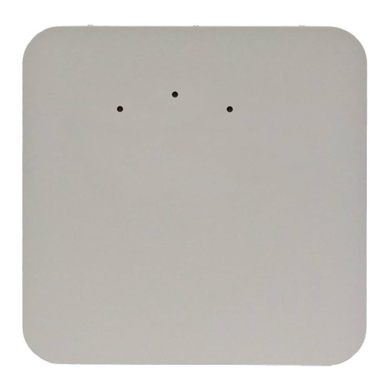
External Hardware Features for the WLA620 Figure 1–1 and Figure 1–2 below show the external hardware features of the WLA620. Figure 1–1. WLA Model WLA620—Bottom View Ethernet Port... -
Page 16: External Antenna Options
The WLA620 unit does not include an integrated antenna, but provides various external antenna options for both 5 GHz and 2.4 GHz operation. The WLA620 unit requires the 2.4 GHz 8 dBi omnidirectional external antenna for 2.4 GHz operation. The following... -
Page 17: Receive Signal Strength Indicator (Rssi) Bnc Connector
MP-620 Local Network The WLA620 does not have a power switch. It is powered on when the Ethernet port is connected to the power injector module, and the power injector module is connected to an AC power source. The power injector includes one LED indicator that turns on when AC power is applied. -
Page 18: System Configuration
WLA620, WLA622 and WLA632 Overview System Configuration At each location where an WLA620 unit is installed, it must be connected to the local network using the power injector module. The following figure illustrates the system component connections. Figure 1–4. System Component Connections... -
Page 19: External Hardware Features For The Wla622
WLA620, WLA622 and WLA632 Overview External Hardware Features for the WLA622 Figure 1–5. MP Access Point Model WLA622—Bottom View Figure 1–6. Access Point Model WLA622—Top View. Antenna ports are numbered from the left 1 to 4. Port 2 Port 3... -
Page 20: Led Indicators
WLA620, WLA622 and WLA632 Overview LED Indicators The LEDs are used for RSSI signal strength measurements to aim directional antennas and to indicate the state of the WLA. The access point includes eight status LED indicators, as shown below. The LEDs are viewed right to left as you look at the back of the WLA. -
Page 21: External Antenna Options
WLA620, WLA622 and WLA632 Overview Table 3: Wireless Status LEDs in WLA Mode Status Description 11b/g Slow Flashing The 802.11b/g radio is enabled with a low level of network activity. Amber (three LEDs) Fast Flashing Indicates a medium level of network activity. -
Page 22: Ethernet Port
WLA620, WLA622 and WLA632 Overview The WLA622 supports four antenna ports, two for the 11a radio and two for the 11bg radio. The supported antennas models are: 802.11bg Radio ANT-1120-OUT ANT-1360-OUT 802.11a Radio ANT-5120-OUT ... -
Page 23: Grounding Point
Lightning Protector for Outdoor Antenna If you are using the WLA622 with an outdoor antenna, Juniper Networks strongly recommends installing an external lightning protector for the antenna. An external lightning protector may be obtained from Juniper Networks. -
Page 24: Features And Benefits
WLA620, WLA622 and WLA632 Overview Figure 1–8. System Component Connections External Antenna Lightning Protector RF Coaxial Cable Indoor Outdoor WLA622 Unit LAN Switch Ethernet Cable Ethernet Cable Power Injector AC Power Ground Wire Features and Benefits The WLA622 provides the following features and benefits: The WLA622 supports access point services for the 5 GHz and 2.4 GHz radios using... -
Page 25: External Hardware Features For The Wla632
WLA620, WLA622 and WLA632 Overview External Hardware Features for the WLA632 Power Ethernet Port 5GHz Antenna Ports Copyright © 2012, Juniper Networks, Inc. -
Page 26: External Antenna Options
WLA620, WLA622 and WLA632 Overview Informational Note: Two separate cables are required for power and ethernet function on the WLA632. Both the cable dongles are RJ45 on one end, but one cable is specific to power and one is specific to data. If the RJ45 cable ends are swapped, the unit will not power up but will not be damaged. -
Page 27: Multiple External Antenna Support
Ethernet interface on the Ethernet input connector. The WLA is configured as auto MDI/MDIX. The WLA632 is powered from the WLA-XPS9001GO power supplies. Caution: The WLA622 and WLA632 must only be used with a Juniper Networks-approved WLA-XPS9001GO outdoor power supply in order to prevent possible damage to the unit. - Page 28 Lightning Protector for Outdoor Antenna If you are using the WLA632 with an outdoor antenna, Juniper Networks strongly recommends installing an external lightning protector for the antenna. An external lightning protector may be obtained from Juniper Networks.
-
Page 29: Features And Benefits
Seamless roaming within the IEEE 802.11 a/b/g/n WLAN infrastructure. Adjustable output power support Interoperability with Juniper Networks Wireless Security Switch Auto-sensing 10/100/1000 Ethernet port with auto MDI/MDI-X but has no PoE support on the 10/100/100 (data) port Comply with IEEE 802.3, 802.3u and 802.3ab... - Page 30 WLA620, WLA622 and WLA632 Overview Copyright © 2012, Juniper Networks, Inc.
-
Page 31: Chapter 2 Wla Series Network Configurations
This chapter illustrates network configurations supported for the Juniper Networks WLAs. Infrastructure Configuration In an infrastructure topology, the WLA620, WLA622, and WLA632 provide access to a wired LAN for 802.11a/b/g wireless workstations (802.11 a/b/g/n with WLA632 only). The WLA620, WLA622 and WLA632 have weatherproof casing and can be installed outdoors (for example, on a pole) to provide network access to clients located outside. -
Page 32: Wlan Mesh Configuration
802.11a radio) can be used for Mesh Link communications, using an SSID reserved for this purpose, while the Mesh WLA can use its other radio for client associations in the same way a non-Mesh WLA can. Copyright © 2012, Juniper Networks, Inc. -
Page 33: Wireless Bridge Configuration
WLA Series Network Configurations Wireless Bridge Configuration You can use WLAN mesh services in a wireless bridge configuration, with the WLA620, WLA622 or WLA632 units serving as bridge endpoints in a transparent Layer 2 bridge. A typical application of wireless bridging is to provide network connectivity between two buildings using a wireless link, as shown in the following illustration. - Page 34 WLA620 Mesh WLA Mesh WLA WLA620 WLA620 WLA620 Mesh WLA Mesh WLA Mesh Portal WLA with Omnidirectional Antenna WLA620 Mesh WLA WLA620 WLA620 Mesh WLA Mesh Portal WLA with Sector Antenna WLA620 Mesh WLA Copyright © 2012, Juniper Networks, Inc.
-
Page 35: Chapter 3 Installing And Connecting An Access Point
RingMaster Network Plan and Work Orders If you are using RingMaster to plan your Juniper Networks Mobility System installation, you might want to create and verify a network plan for the entire Juniper Networks installation and generate an WLA work order, before installing WLAs. A... -
Page 36: Ethernet Cabling
The WLA620, WLA622, and WLA632 can operate in winds up to 144 km/h (90 mph) and survive higher wind speeds up to 201 km/h (125 mph). -
Page 37: Grounding
For additional radio safety warnings, the Regulatory Guide document. Installing a WLA620 The WLA620 includes a bracket kit for mounting the unit to a 3.81 to 5.08 cm (1.5 to 2 inch) diameter steel pole or tube. The pole-mounting bracket allows the unit to be mounted to part of a radio mast or tower structure. -
Page 38: Mounting The Unit
Use one of the following procedures. Informational Note: If you are installing the WLA620 as a Mesh WLA in a WLAN Mesh or wireless bridge configuration, and the WLA will not have a wired link to a WLA, you must configure the WLA connection using a wired link to an WLC switch before deploying the WLA620 in a final location. -
Page 39: Connecting External Antennas
5 GHz antenna. Perform these steps: 1. Mount the external antenna to the same supporting structure as the WLA620, within 3 m (10 ft) distance, using the bracket supplied in the antenna package. 2. If you are installing the optional lightning arrestor for an outdoor antenna, perform the following steps. - Page 40 6-gauge Grounding Cable a. Connect one end of the short RF coaxial cable to the WLA620 N-type connector, and connect the other end to the lightning arrestor. b. Connect one end of the 3m RF coaxial cable to the lightning arrestor, and connect the other end to the outdoor antenna.
-
Page 41: Connecting Cables To The Unit
1. Ground the unit with an appropriate grounding wire (not included) by attaching it to the grounding screw on the unit 2. Attach the Ethernet cable to the Ethernet port on the WLA620. Informational Note: The Ethernet cable included with the package is 30 m (100 ft) long. -
Page 42: Connecting The Outdoor Power Supply
You can use the CLI or RingMaster to configure an WLA connection. If you are installing the WLA620 as a Mesh WLA in a WLAN Mesh or wireless bridge configuration, you must configure the WLA connection before deploying the WLA620 in its final location. -
Page 43: Aligning Antennas For Bridge Or Mesh Links
For accurate alignment, you must connect a DC voltmeter or RSSI meter to the BNC connector on the WLA620 and monitor the voltage as the antenna moves horizontally and vertically. - Page 44 5 per second. When the WLA620 receives a link calibration packet, it emits a voltage to the RSSI meter proportional to the received signal strength of the packet. This can aid in positioning the WLA620 where it has a strong signal to the WLA sending out the packets.
- Page 45 Voltmeter 3. Pan the antenna horizontally back and forth while checking the RSSI voltage. If using the pole-mounting bracket with the WLA620, you must rotate the mounting bracket around the pole. Other external antenna brackets may require a different horizontal adjustment.
-
Page 46: Installing An Wla622
1. Place the V-shaped part of the bracket around the pole and tighten the securing nuts just enough to hold the bracket to the pole. (The bracket may need to be rotated around the pole during the alignment process.) Copyright © 2012, Juniper Networks, Inc. - Page 47 Figure 3–10. Attaching the Bracket to the Pole 2. Fit the edges of the V-shaped part into the slots in the rectangular plate, and use the included nuts to tightly secure the WLA622 to the bracket. Copyright © 2012, Juniper Networks, Inc.
- Page 48 Be sure to take account of the antenna polarization direction. All antennas in a link must be mounted with the same polarization. Copyright © 2012, Juniper Networks, Inc.
- Page 49 It is intended for use with the unit using an external antenna. 1. Always attach the bracket to a wall with the flat side flush against the wall (see following figure). Figure 3–12. Wall-Mounting Bracket Copyright © 2012, Juniper Networks, Inc.
-
Page 50: Connecting External Antennas
10 ft (3 m) distance, using the bracket supplied in the antenna package. 2. If you are installing the optional lightning arrestor for an outdoor antenna, perform the following steps. Otherwise, skip to step 5. Copyright © 2012, Juniper Networks, Inc. - Page 51 Installing and Connecting an Access Point a. Solder the ground wire to the ground-wire terminal lug supplied with the lightning arrestor. Juniper Networks recommends that you use 6-gauge cable for the ground wire. The ground wire must be properly earthed in order to provide adequate protection.
-
Page 52: Connecting Cables To The Unit
Ethernet cable enters the building. Caution: Be sure that grounding is available and that it meets local and national electrical codes. For additional lightning protection, use lightning rods, lightning arrestors, or surge suppressors. Copyright © 2012, Juniper Networks, Inc. - Page 53 WLC that provides IEEE 802.3af PoE. For power, always connect the unit only to the included WLA-XPS9001GO PSU. 1. Connect the Ethernet cable from the wireless bridge to the PoE port labeled “DATA PWR OUT” on the PSU.. Copyright © 2012, Juniper Networks, Inc.
-
Page 54: Checking The Led Indicators
One fully lit LED indicates a low traffic rate, two LEDs.a medium rate, and three LEDs the maximum rate. A flashing LED indicates an intermediate traffic rate level No link is present or the 802.11a radio is disabled. Copyright © 2012, Juniper Networks, Inc. -
Page 55: Connecting A Wla To A Wlc
Ethernet Cable WLA, server or (Cat 5 cable) other device 1. Insert a Cat 5 cable with a standard RJ45 connector as shown in Figure 3–7. For connection to an WLA, use a straight-through cable. Copyright © 2012, Juniper Networks, Inc. -
Page 56: Aligning Antennas For Bridge Or Mesh Links
LEDs that turn on, the stronger the signal. (RSSI level 1 should equate to the lowest useful signal). Alternatively, you can monitor the Receive Signal Strength Indicator (RSSI) value directly from the management interface. The higher the RSSI value, the stronger the signal. Copyright © 2012, Juniper Networks, Inc. - Page 57 If the second antenna is being aligned with a different WLA, disable link-calibration on the original WLA and enable it on the new WLA. Once both antennas are properly aligned, connect them to their desired ports. Copyright © 2012, Juniper Networks, Inc.
- Page 58 3. Loosen the vertical adjustment on the mounting bracket and tilt the antenna slowly up and down while checking the LEDs. Find the point where the signal is strongest and secure the vertical adjustment in that position. Copyright © 2012, Juniper Networks, Inc.
-
Page 59: Installing An Wla632
You also have the option to mount the WLA on a larger pole (up to 30.48 cm or 12-inch diameter) using the bracket kit and two metal band straps (straps not provided by Juniper Networks). Hardware installation of the WLA632 involves these steps: 1. - Page 60 1. Insert the four large screws (included in kit) through the four circular holes in the bracket as shown below. 2. Position the flat bracket behind the pole as shown below and align the screws on the front bracket with the holes in the flat bracket. Copyright © 2012, Juniper Networks, Inc.
- Page 61 3. Insert the four screws into the holes on the flat bracket and secure the brackets to the pole using the provided split washers and nuts. 4. Position the WLA632 unit so that the mounting holes overlap with the same-sized holes on the pole-mounting bracket. Copyright © 2012, Juniper Networks, Inc.
- Page 62 (not included in the kit). The two steel band straps can be threaded through the rectangular holes in the bracket to secure it to a larger diameter pole. This method is shown in the following figure. Copyright © 2012, Juniper Networks, Inc.
- Page 63 1. Position the bracket on the intended wall location and drill four large screws (not included in kit) in through the circular holes on the bracket until it is firmly secured to the wall. Copyright © 2012, Juniper Networks, Inc.
-
Page 64: Connecting External Antennas
Connecting External Antennas The supported antennas models are: 802.11bgn Radio ANT-7360A-OUT (stick, N-type jack) If this antenna is used the unused center antenna port must be terminated. ANT-77555-OUT (3 RP-SMA jack) Copyright © 2012, Juniper Networks, Inc. -
Page 65: Multiple External Antenna Support
Ethernet interface on the Ethernet input connector. The WLA is configured as auto MDI/MDIX and is powered from the WLA-XPS9001GO power supplies. Caution: The WLA622 and WLA632 must only be used with a Juniper Networks-approved WLA-XPS9001GO power supply in order to prevent possible damage to the unit. -
Page 66: Connecting Cables To The Unit
2. Attach the Ethernet cable to the Ethernet port on the WLA632. 3. For extra protection against rain or moisture, apply weatherproofing tape (not included) around the Ethernet connector. Copyright © 2012, Juniper Networks, Inc. - Page 67 IEEE 802.3af PoE. Always connect the unit to the included power injector module. Informational Note: The WLA622 and WLA632 must only be used with a Juniper Networks-approved WLA-XPS9001GO outdoor power supply in order to prevent possible damage to the unit.
-
Page 68: Connecting An Wla To An Wlc
1. Insert a Cat 5 cable with a standard RJ45 connector. For connection to a WLA, use a straight-through cable. 2. When the link is activated, observe the WLA LED for the port on the WLC: Copyright © 2012, Juniper Networks, Inc. - Page 69 Informational Note: The WLC 10/100 Ethernet ports are configured as wired network ports by default. You must change the port type for an WLC port directly connected to a WLA to activate the link. Copyright © 2012, Juniper Networks, Inc.
- Page 70 Installing and Connecting an Access Point Copyright © 2012, Juniper Networks, Inc.
-
Page 71: Chapter 4 Wla Series Technical Specifications
Guide document. Informational Note: This Listed Accessory is designed and approved to be used only with Juniper Networks WLC models WLC8 and WLC2. (The WLC200 does not directly connect to the WLA.) Informational Note: The WLA radios are disabled by default and can be enabled only by the system administrator using the RingMaster management application or the WLC’s... - Page 72 WLA Series Technical Specifications Table 1: WLA620 and WLA622 Mechanical and Compliance Specifications Specification Description Operating Frequency 802.11a: 5.15 GHz to 5.825 GHz based on country regulations 802.11b/g: 2.4 GHz to 2.4835 GHz based on country regulations Power Injector (WLA620) Input: 100-240 VAC, 47-63 Hz, 1.5 A...
- Page 73 Storage: -40 to 70 °C (-40 to 158 °F) Humidity OK Each WLA632 will operate with a single base MAC Address, and will consume 64 sequential MAC Addresses after the base MAC address for a total of 32 addresses allocated per radio Copyright © 2012, Juniper Networks, Inc.
-
Page 74: Federal Communication Commission Interference Statement
For product available in the USA/Canada market, only channel 1~11 can be operated. Selection of other channels is not possible. This device and its antenna(s) must not be co-located or operation in conjunction with any other antenna or transmitter. Copyright © 2012, Juniper Networks, Inc. - Page 75 The maximum antenna gain permitted (for devices in the band 5725-5825 MHz) to comply with the e.i.r.p. limits specified for point-to-point and non point-to-point operation as appropriate, as stated in section A9.2(3). Copyright © 2012, Juniper Networks, Inc.
-
Page 76: Mac Addresses
All MAC addresses on a WLA are assigned based on the WLA’s base MAC address, as described in Table 3. Table 3: MAC Address Allocations on WLA620, WLA622, and WLA632 The WLA has a base MAC address. All the other addresses are assigned based on this WLA base MAC Address address. -
Page 77: Dbi Omnidirectional (5 Ghz)
Gain 8 dBi VSWR 2.0 : 1 max Polarization Linear, vertical HPBW Horizontal: 360° Downtilt 0° Power Handling 5 W (cw) Impedance 50 Ohms Connector N type, female Radome Material: Fiber glass Color: Gray-white Copyright © 2012, Juniper Networks, Inc. -
Page 78: 13.5 Dbi 120-Degree Sector
Temperature: -40 °C to 80 °C (-40° F to 176° F) Humidity: 95% @ 25 °C (77° F) Mechanical Dimensions: 62 x 8.8 x 7 cm (24.4 x 3.46 x 2.76 in) Weight: 590 g (1.3 lbs) Copyright © 2012, Juniper Networks, Inc. - Page 79 Temperature: -40 °C to 80 °C (-40° F to 176° F) Humidity: 95% @ 25 °C (77° F) Mechanical Dimensions: 75 x 8.8 x 7 cm (29.5 x 3.46 x 2.76 in) Weight: 700 g (1.5 lbs) Copyright © 2012, Juniper Networks, Inc.
-
Page 80: 18 Dbi 18-Degree Panel
Table 9: Signal Loss Levels from Lightning Protector and Coaxial Cable Loss from Lightning Loss from Loss from Frequency Protector 3m cable 1.8m cable 2.4 GHz 0.08 dBi 0.75 dBi 0.59 dBi 5.5 GHz 0.25 dBi 1.17 dBi 0.89 dBi Copyright © 2012, Juniper Networks, Inc. -
Page 81: Antenna Specifications For Wla632
Multi-element antennas (an antenna with multiple antenna elements) have multiple antenna cables, one for each antenna element. Some single-element omni stick antennas, on the other hand, do not require an antenna cable in order to attach to an antenna connector. Copyright © 2012, Juniper Networks, Inc. -
Page 82: Supported Antennas
1. There is only one antenna in use for radio 2, while there are two antenna elements in use for radio 2. Supported Antennas The table below lists the Juniper Networks supported antenna configurations. Table 11: Juniper Supported Antennas Number of Antennas... -
Page 83: Wla632 Mechanical And Compliance Specifications
WLAs that can receive these packets use LED patterns to indicate the RSSI level of received calibration packets (the WLA620 must be connected to an external RSSI meter to measure RSSI levels). Each RSSI level represents about a 5dBm range. - Page 84 WLA Series Technical Specifications Table 13: 2.4G Ch.13 LED 1 LED 2 LED 3 RSSI Operational signal Flashing Slow Flashing Fast Strong signal Copyright © 2012, Juniper Networks, Inc.
-
Page 85: Chapter 5 Cables And Pinouts
Cables and Pinouts This chapter describes the wiring and pin assignments for the cables and connectors that can be used with the WLA620, WLA622 and WLA632. Twisted-Pair Cable Assignments for the WLA620 and WLA622 For 10/100BASE-TX connections, a twisted-pair cable must have two pairs of wires. -
Page 86: Straight-Through Wiring
“crossover” cable for network connections to PCs, servers or other end nodes that only have MDI ports. However, if the device to which you are connecting supports automatic MDI/MDI-X operation, you can use either “straight-through” or “crossover” cable. Copyright © 2012, Juniper Networks, Inc. -
Page 87: 8-Pin Din Connector Pinout For The Wla620 And Wla622
WLA622 The Ethernet cable from the power injector connects to an 8-pin DIN connector on the WLA620 and WLA622. This connector is described in the following figure and table. Figure 5–4. 8-Pin Ethernet DIN Connector Table 2: 8-Pin DIN Ethernet Port Pinout... -
Page 88: 8-Pin Din To Rj45 Cable Wiring
To construct an extended Ethernet cable to connect from the power injector’s RJ45 Output port to the WLA620 and WLA622’s 8-pin DIN connector, follow the wiring diagram below. Use Category 5 or better UTP or STP cable, maximum length 100 m (328 ft), and be sure to connect all four wire pairs. - Page 89 +48 VDC power 3+ +48 VDC power 3- Receive Data minus (RD-) Return power 4+ Return power 4- Note: The “+” and “-” signs represent the polarity of the wires that make up each wire pair. Copyright © 2012, Juniper Networks, Inc.
- Page 90 Cables and Pinouts Copyright © 2012, Juniper Networks, Inc.
-
Page 91: Chapter 6 Wireless Bridge Link Planning
Radio Path Planning Although the WLA620 uses IEEE 802.11a radio technology, which is capable of reducing the effect of multipath signals due to obstructions, the wireless bridge link requires a “radio line-of-sight” between the two antennas for optimum performance. -
Page 92: Antenna Height
The minimum height required depends on the distance of the link, obstacles that may be in the path, topology of the terrain, and the curvature of the earth (for links over 3 miles). Copyright © 2012, Juniper Networks, Inc. - Page 93 Building B is only three stories high, or 9 m (30 ft), but is located at an elevation that is 12 m (39 ft) higher Copyright © 2012, Juniper Networks, Inc.
-
Page 94: Radio Interference
The WLA620 can operate in winds up to 144 km/h (90 mph) sand survive higher wind speeds up to 125 mph. -
Page 95: Ethernet Cabling
Ethernet Cabling When you have determined a suitable location for the WLA620, WLA622, or WLA632, you must plan a cable route from the WLA outdoors to the power injector module indoors. Consider these points: The Ethernet cable length should never be longer than 100 m (328 ft) over CAT5, ... -
Page 96: Wla Radio Safety Advisories
Transmitters specifies a safety standard for human exposure to radio frequency electromagnetic energy emitted by FCC-certified equipment. When used with the proper antennas (shipped in the product), Juniper Networks MP access point products meet the uncontrolled environmental limits found in OET-65 and ANSI C95.1-1991.
Need help?
Do you have a question about the WLA620 and is the answer not in the manual?
Questions and answers