
Related Manuals for Schwinn 20 Series Bike


Summary of Contents for Schwinn 20 Series Bike
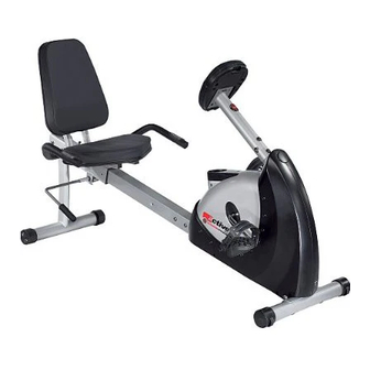
- Page 1 20 Series Recumbent Bike Assembly Manual Nautilus Bowflex Schwinn Fitness Pearl Izumi StairMaster Universal Nautilus Institute ® ® ® ® ® ® ® 001-7214-010808A...
-
Page 2: Table Of Contents
Table of Contents Product Specifications ................2 Safety Warnings ..................3 Exploded Drawing .................4 Parts List ....................5 Hardware Guide ..................6 Assembly Steps ..................8 Contact Information ................15 Product Specifications Dimensions xx” L xx” W x xx” H (xxcm x xxcm x xxcm) Assembled Unit Weight 73 lbs (33.2 kg) Packaged Shipping weight 81.4 lbs (37 kg) -
Page 3: Safety Warnings
Contact your doctor before using the machine again. • Examine this machine for loose parts or signs of wear. Pay special attention to the seat, pedals, and crank arms. Contact Nautilus Customer Service for repair information. Use only genuine Schwinn replacement parts supplied by ®... -
Page 4: Exploded Drawing
Exploded Drawing 24 9 Note: Some component images are for general reference only and may not represent the actual shape or detail of the part. Assembly is unaffected. Assembly Manual... -
Page 5: Parts List
Parts List PARTS LIST Ref. Description Main Frame Front Stabilizer Rear Stabilizer Saddle Support Frame Rail Tube Handlebar Saddle Back Cushion Pulse Wire Connector Console (Computer) Left Pedal Right Pedal Carriage Bolt M10 x 70mm Acorn Nut M10 Arc Washer ID 10.5; OD 25mm; T 1.5mm Hex Screw M8 x 15mm Flat Washer ID 8.4mm;... -
Page 6: Hardware Guide
Hardware Guide Ref. Description Carriage Bolt M10 x 70mm 2pcs Acorn Nut M10 2pcs Arc Washer ID 10.5mm; OD 25mm; T 1.5mm 2 pcs Hex Screw M8 x 15mm 16pcs Flat Washer ID 8.4mm; OD 16mm; T 1.5mm 14pcs Limit Rubber Pad 2pcs Phillips Head Screw M6 x 35mm 8pcs... - Page 7 Assembly Basic Assembly Principles Here are a few basic tips that will aid in the assembly process. By using these principles, you can simplify each process and save yourself extra time and effort. 1. To make the assembly process go faster, gather the pieces you need for each step and thoroughly read the assembly instructions for that step prior to starting assembly for the step.
-
Page 8: Assembly Steps
Assembly Steps Step 1: Install Front Stabilizers 1-1: Install Front Stabilizer (2) to Main Frame (1) using 2 Parts: Carriage Bolts (13), 2 Arc Washers (15), and 2 Acorn • #2 - Front Stabilizer (Qty 1) Nuts (14) as indicated (Figure 1). •... - Page 9 Assembly Steps Step 2: Assemble Saddle Support Parts: 2-1: Slide Saddle Support Frame (4) onto Rail Tube (5) as shown in Figure 2. The wires from the Rail Tube pass • #4 - Saddle Support Frame (Qty 1) through the Saddle Support Frame. •...
- Page 10 Assembly Steps Step 3: Install Rail Tube Assembly to Main Frame Parts: 3-1: Connect the Lower Pulse Wire (22) to the Middle Pulse Wire (23) as shown in Figure 3A. • Main Frame Assembly (#1) from Step 1 • Rail Tube Assembly (#5) from Step 2 3-2: Slide the Rail Tube Assembly (5) onto the Main Frame •...
- Page 11 Assembly Steps Step 4: Attach Rear Stabilizer Bar Parts: 4-1: Attach the Rear Stabilizer Bar (3) to the Rail Tube (5) using 4 Hex Screws (16) and 4 Flat Washers (17). • #3 - Rear Stabilizer Bar (Qty 1) • #5 - Rail Tube Assembly (Qty 1) Note: Make sure the Rear Stabilizer Bar (3) is •...
- Page 12 Assembly Steps Step 5: Attach Handlebar to Saddle Support Frame Parts: 5-1: Attach the Handlebar (6) to Saddle Support Frame (4) using 4 Hex Screws (26) and 4 Flat Washers (17) • #4 - Saddle Support Frame (Qty 1) as shown in Figure 5. •...
- Page 13 Assembly Steps Step 6: Attach Cushions Parts: 6-1: Install Saddle (7) and Back Cushion (8) onto the Saddle Support Frame (4) using 8 Phillips Screws • #4 - Support Frame (Qty 1) (20). Insert the Phillips Screws through the screw •...
- Page 14 Assembly Steps Step 7: Mount the Console Parts: 7-1: Feed Lower Pulse Wire (22) and Lower Computer Wire (24) through the Front Post (31). • #22 - Lower Pulse Wire (Qty 1) • #24 - Lower Computer Wire (Qty 1) 7-2: Install the Front Post (31) onto the Main Frame (1), •...
-
Page 15: Contact Information
Assembly Steps Step 8: Install Adjustment Handle Parts: 8-1: Insert the Adjustment Handle (29) into the handle mount (see Detail A). Finish install by tightening • #29 - Adjustment Handle (Qty 1) Screw (30). • #30 - Screw (Qty 1) Note: Do not overtighten and strip the threads on the screw (30). - Page 16 Assembly Steps Step 9: Install Pedals Parts: 9-1: Install the Left Pedal (11) to Left Crank (19). Install Right Pedal (12) to the Right Crank. • #11 - Left Pedal (Qty 1) • #12 - Right Pedal (Qty 1) Note: The Left Pedal has a left handed thread •...
- Page 17 Assembly Steps Step 10: Final Inspection 10-1: Tighten all hardware. 10-2: Read warnings on machine. Please read and refer to the Owner’s Manual for: • Operating Instructions • Maintenance Instructions • Warranty Information. Failure to visually check and test assembly before use can cause damage to the equipment. It can also cause serious injury to users and bystanders.
- Page 18 Assembly Assembly Manual...
- Page 19 Contact Information UNITED STATES OFFICES: INTERNATIONAL OFFICES: For technical assistance and a list of distributors in your E-mail: customerservice@nautilus.com area, please call or fax one of the following numbers. TECHNICAL/CUSTOMER SERVICE INTERNATIONAL CUSTOMER SERVICE Phone: 800-NAUTILUS (800-628-8458) Nautilus International S.A. Fax: (877) 686-6466 Rue Jean Prouvé...
- Page 20 ©2008. Nautilus, Inc. All rights reserved. Nautilus, the Nautilus Logo, Universal, the Universal Logo, Bowflex, StairMaster, Pearl Izumi, Nautilus Institute and Active Series are either registered trademarks or trademarks of Nautilus, Inc. Schwinn and the Schwinn Quality Seal are registered trademarks. All other trademarks are owned by their respective companies.
Need help?
Do you have a question about the 20 Series Bike and is the answer not in the manual?
Questions and answers