Advertisement
Quick Links
Download this manual
See also:
Owner's Manual
Advertisement

Summary of Contents for Schwinn 202
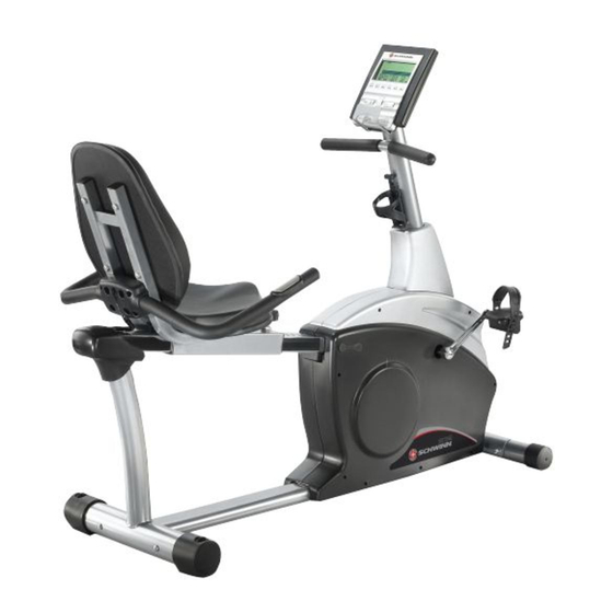
- Page 1 202 Schwinn Recumbent Exercise Bike ® Parts List Full Size Hardware Chart Product Illustration Assembly Instructions 202 Recumbent Exercise Bike...
-
Page 2: Important Precautions
9. Read all warnings posted on the exercise bicycle. 10. User weight limit on the Schwinn 202 is 300 lbs. This Schwinn 202 is intended for home use only. Do not use this equipment in any non-residential environment. WARNING: Before beginning this or any exercise program, consult your physician. - Page 3 • A flat area of 5’ x 7’ is suggested to assemble the 202 exercise bike. • You will need the following tools to complete the assembly:...
-
Page 4: Parts List
Check Quantity Parts List Description Allen Bolt M8 x P1.25 x 45mm Flat Washer Seat Pin Adjustment Knob Seat Seat Back Handlebar Assembly Flat Washer ф8*ф16*2T Seat Frame Assembly Seat Rail Rear Stabilizer Tube End Cap (for #9) Buffer Buffer Plate Flat Washer for 12/13 Screw for 12/13 Carriage Bolt M8 x P1.25 x 75mm... - Page 5 Stage#1 Allen Bolt M8xP1.25x16mm Flat Washer for ф 8* ф 16* 2T Flat Washer ф 8* ф 19* 2T Stage#4 Allen Bolt M8xP1.25x16mm Acorn Nut M8 Flat Washer ф 8* ф 16* 2T Flat Washer ф 8* ф 19* 2T Note: Please verify you have all correct parts and quantities before assembling unit.
- Page 6 202 Assembly Drawing with Reference Numbers...
-
Page 7: Replacement Parts List
Replacement Parts List Reference # Seat Pin Adjustment Knob Seat Seat Back Handlebar Assembly Seat Rail Rear Stabilizer Tube Seat Rail End Cap Buffer Buffer Plate Flat Washer Screws Carriage Bolt M8 x P1.25 x 75mm Front Stabilizer Tube (w/wheels) Acorn Nut Pedals (Left &... - Page 8 IMPORTANT!: To ensure ease of assembly please verify the size and quantity of all the required assembly hardware and parts with the enclosed parts list and full size hardware chart. Each step of the assembly process has been ro stages. Please take just a few moments to read over these instructions to familiarize yourself with the process to make assembly quick and trouble-fre Assembly Stage #1 Assemble Seat and Handle Bar...
- Page 9 Step 3: Attach SEAT BAC K (#5) to SEAT FRAME (#8 ) with 4 ALLEN BOL (#1) and 4 WASHERS (#2). Tighten Bolts. Note: Finished seat should look like picture below:...
- Page 10 Assembly Stage #2 Attach Rear Stabilizer and Seat Rai l to Seat Assembly Assembly hardware required: (4) M8 Allen Bolts 16mm (item #22) (4) Flat Washers Ø8 * Ø19 * 2T(item#2) Step 4: Attach SEAT RAIL (#9) to REAR STABILIZER TUBE (#10) with 4 FLAT WASHERS (#2) and 4 ALLEN BOLTS (#22).
- Page 11 Assembly Stage #3 Attach Front Stabilizer Tube and Pedals to Main Unit Assembly Hardware Required: Step 8: Attach FRONT STABILIZER TUBE (#17) to the MAIN UNIT (#31) with the M8 BOLT 75mm (#16), CURVED WASHER (#19), and ACORN NUT (#20). Tighten Bolts with provided wrench.
- Page 12 Assembly Stage #4 Attach Se at Rail and Lower Base Frame to M Assembly Hardware Required: p 10: Slide the LOWER BASE FRAME (#32) into the MAIN UNIT (#31), attach h 3, 16mm BOLTS (#22) and 3 FLAT WASHERS (#2). Do not completely tighte il after step 12.
- Page 13 Before proceeding to step 11 please complete the following steps. Failure to do so could lead to damage to the handgrip heart rate wires! 1) Remove END CAP (#11) from the end of the seat rail. The coiled wire seen above the seat rail needs to be re-routed out the back of the seat rail .
- Page 14 Assembly Stage #5 Attach Console Mast to Main Unit Step 16 Assembly Hardware Required: (4) Allen Bolts 16 mm long (item #22) tep 13: Run CONSOLE MAST (#30) through the CONSOLE MAST COVER (#27) nd onto the MAIN UNIT (#31). Before fastening the CONSOLE MAST, attach both R CABLES (#29 &...
- Page 15 Step 15: Attach UPPER COMPUTER CABLE (#28) and HR CABLE (#29) to under de of COMPUTER (#34). Place COMPUTER (#34) on top of CONSOLE MAST (#30), the reading rack should wrap around the bottom of the COMP UTER. Attach COMPUTER to CONS OLE MAST with COMPUTER MOUNTIN G SCREWS (#33).
- Page 16 Troubleshooting the Schwinn 202 Recumbent IP: Use assembly diagram(s) as reference when troubleshooting unit. PROBLEM: Computer will not start, function, or is blank… (SOLUTION): 1. Ensure the unit is plugged into a 110v outlet. 2. Check the wiring connections a made to the computer.


Need help?
Do you have a question about the 202 and is the answer not in the manual?
Questions and answers
What size crank puller for schwinn 202