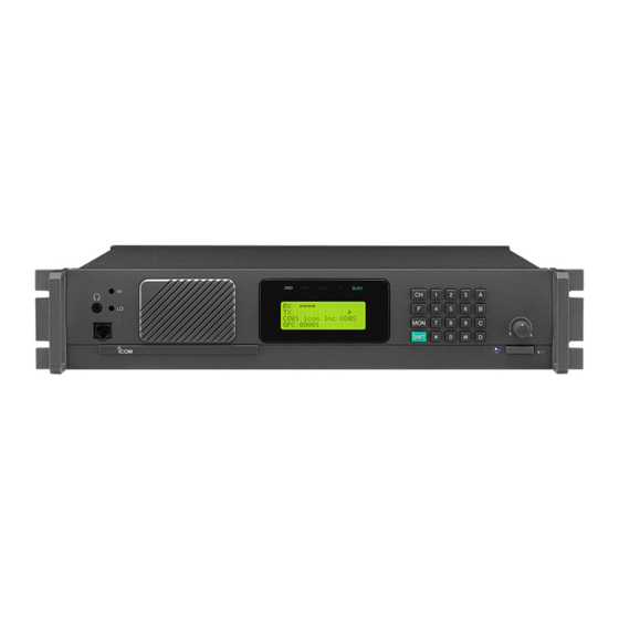
Summary of Contents for Icom IC-FR9020
- Page 1 INSTRUCTION MANUAL VHF P25 REPEATER iFR9010 UHF P25 REPEATER iFR9020 This device complies with Part 15 of the FCC Rules. Operation is subject to the condition that this device does not cause harm- ful interference.
-
Page 2: Forward
Icom is not responsible for the destruction or damage tenna easily during transmission. This may result in an to an Icom repeater in the event the Icom repeater is electrical shock or burn. used with equipment that is not manufactured or ap- proved by Icom. -
Page 3: Safety Training Information
Icom, Icom Inc, and the Icom logo are registered trademarks of Icom Incorporated (Japan) in Japan, the United States, the United Kingdom, Germany, France, Spain, Russia and/or other coun- tries. - Page 4 RF de la FCC et d’IC, pour une «utili- ricant ou une antenne spécialement autorisée par le sation grand public». En outre, votre radio Icom satis- fabricant pour être utilisée avec cette radio. • NE PAS émettre pendant plus de50% du temps fait les normes et directives qui suivent en matière de...
-
Page 5: Table Of Contents
TABLE OF CONTENTS 22.2 DIGITAL ............8 FORWARD ..............i 22.3 MIXED ............8 IMPORTANT .............. i 23 REMOTE CONTROL ........... 8 EXPLICIT DEFINITIONS ..........i 24 DISPLAYING THE FIRMWARE VERSIONS ..9 PRECAUTIONS ............i 25 DISPLAYING THE SERIAL NUMBER ....9 SAFETY TRAINING INFORMATION ......ii FCC INFORMATION ..........ii 26 DISPLAYING THE PROGRAMMING SOFTWARE... -
Page 6: Lcd Display
1 LCD DISPLAY 3 KEY CONTROLS LCD display consists of 4 x 20 characters as shown. 3.1 Key entry without [SHIFT] key [0]–[9] = Channel numbers and individual call RX = = = = = = = = = = address (target address) TX = = = = = = = = = = [A] = P25 calls (Group Call, All Call, and... -
Page 7: Control Knob
4 CONTROL KNOB 5 CHANNEL SELECTION 4.1 VOLUME The IC-FR9010/FR9020 has capability of up to 500 channels. Rotate the knob to change the volume level. Push [CH], and then enter the channel number. The volume level varies from 0 to 34. If the lo- Example-1 CH-8;... -
Page 8: Individual Call Entry (Digital Base Mode Only)
8 P25 CONVENTIONAL CONTROL 6.1 INDIVIDUAL CALL ENTRY (Digital Base Mode Only) SIGNALLING (SBC) (DIGITAL Push and release [A] repeatedly until “IDC-----” is BASE MODE ONLY) displayed. Push [B], and enter the numerical Unit ID. To deleted a digit, push the star [Q] key. Push [B] NOTE: SBC functions are selectable in the Program- or [#] to complete entry. -
Page 9: Call Alert
8.2 CALL ALERT 8.5 RADIO UNINHIBIT To send a Call Alert, push [F] then push [A] or [B] Used to enable a subscriber unit that has been until the selection is displayed, then enter the tar- disabled, the password must match the password get ID of the radio to alert and push [#]. -
Page 10: Predefined Messages
9 P25 SQUELCH ADJUSTMENT 8.8 PREDEFINED MESSAGES Used to send a predefined system message. Push [SHIFT] + [MON] to choose the P25 squelch mode. To send a Predefined Message, push [F] then push Normal SQL = If NAC is the same, the receiver will [A] or [B] until the selection is displayed, then enter unmute the target radio ID, push [D] and enter a message... -
Page 11: Key-Lock
Figure 30 be enabled in programming to use these functions.) Figure 26 shows CWID Sending. Figure 27 shows CWID function stop. Figure 28 shows CWID function start. CWID sending Code: ICOM C001 TAC 2 Figure 26 C001 TAC 2 CWID function stop... -
Page 12: Bar Graph/Channel Display
15 P25 CHANNEL DATA 17 LCD BACKLIGHT TOGGLE By Default, the Backlight illuminates for 5 seconds af- Push [SHIFT] + [Q] to scroll through the data, [Q] must ter pushed any key then goes out. Push [SHIFT] + [1] be depressed to scroll. for the backlight to stay ON. -
Page 13: Emergency Call Reception
20 EMERGENCY CALL RECEPTION 22 BASE MODE 22.1 ANALOG The 4th line of the LCD shows the Emergency Alarm when an emergency call is received. The LCD back If the received CTCSS/DCS matches the pro- light flashes and the audible tone heard from the grammed CTCSS/DCS, the radio’s receiver will speaker can be increased or decreased with the vol- open. -
Page 14: Displaying The Firmware Versions
24 DISPLAYING THE FIRMWARE 27 DATA CHECK VERSIONS The IC-FR9010/FR9020 has a self diagnostic function. All data in the EEROM is checked every time the radio Both the radio and DSP firmware versions are indi- is switched ON. If the data is not properly stored, the cated on the LCD after the radio switches ON for 2 radio automatically turns to programming mode. -
Page 15: Rs-232 Error Detection
30 RS-232 ERROR DETECTION If the communications between PC and the repeater have trouble, the following messages are shown on the LCD. - Overrun error - Framing error - Parity error - Unknown command - Data unmatched - Send error - Answer timeout - Receive timeout 31 DSP ERROR DETECTION... -
Page 16: Option Port Pinout
32 OPTION PORT PINOUT 25 pin D-sub connector for remote control is provided on the rear panel of IC-FR9010/FR9020. The functions of each pin are as follows: Pin No. Name Description I/O Levels Comments CH 0 LSB external binary channel 0 to +3.3 V DC 0000 is channel 1 selection CH 1... - Page 17 MEMO...
- Page 18 MEMO...
- Page 19 MEMO...
- Page 20 A-7090H-1EX-0A Printed in Japan © 2013 Icom Inc. 1-1-32 Kamiminami, Hirano-ku, Osaka 547-0003, Japan...


Need help?
Do you have a question about the IC-FR9020 and is the answer not in the manual?
Questions and answers