Table of Contents
Advertisement
Advertisement
Table of Contents

Related Manuals for Fire Sense PH03-SS


Summary of Contents for Fire Sense PH03-SS
- Page 2 TOOLS AND PARTS NEEDED FOR ASSEMBLY DANGER CARBON MONOXIDE HAZARD This appliance can produce carbon monoxide which has no odor. Using it in an enclosed space can kill you. Never use this appliance in a enclosed space such as a camper, tent, car or home. Tools needed WARNING:Improper installation, adjustment, Adjustable opening...
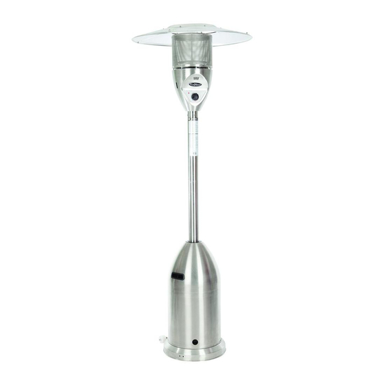
- Page 3 PARTS 1 Center Reflector Cap ● 3 Reflector Pieces ● 1 Head Assembly ● 1 Gas Hose (attached to Regulator 19) ● 1 Upper Post ● 1 Lower Post ● ● 1 Cylinder Cover 3 Post Mounts ● 1 Cylinder Base ●...
- Page 4 PRECAUTIONS NOTE: PLEASE READ THE FOLLOWING SAFETY RULES WARNING: At least once a year, the unit should be inspected for This appliance must only be used outdoors. the presence of spiders, spider webs or other insects. Using this product in an enclosed area may cause Check the heater immediately if any of the following injury, death or property damage.
- Page 5 ASSEMBLY ATTACHING WHEEL ASSEMBLY Step 1 1-1. Locate Wheel Assembly (24) and 2 nuts/bolts contained in Fig. 1 plastic bag with Wheel Assembly (Fig. 1). Step 2 Fig. 2 2-1. Turn Base (9) so that holes for attachment of Wheel Assembly are facing you (Fig. 2). 2-2.
- Page 6 ASSEMBLY WARNING: STEP 1 Proper assembly is the responsibility of the installer. Step 1 Attach 3pcs LPG cylinder fixed parts on the base with 6pcs M6x12mm bolts. Attach post mounts to cylinder base: Place the post mounts on the top of cylinder base, and connect them using 3pcs M8x16 bolts.
- Page 7 ASSEMBLY Step 2 STEP 2 Attach post support to post mounts: Place the post support on the top of post mounts and attach to post mounts using 6pcs M6x18 screw bolts and 6pcs M6 screw caps. STEP 3 Step 3 Attach lower post to base assembly: Attach the lower post to the post mounts using 4pcs M6x10 bolts.
- Page 8 ASSEMBLY Step 4 Step 4 Attach upper post to lower post: Screw the upper post to the lower post as illustrated by turning in a clockwise direction until securely tightened. Step 5 Step 5 Attach cylinder cover to post mounts.
- Page 9 ASSEMBLY Step 6 Attach double pointed bolts to head assembly: Attach M8x90 double pointed bolts (3pcs) to head assembly. Step 7 Step 7 Attach the gas hose to head assembly: Route the gas hose up through the post and out of top, then connect to the head assembly by turning in a clockwise direction.
- Page 10 ASSEMBLY Reflector (#2) is comprised of 3 – outer pieces and 1 – center piece. Locate all 4 pieces of Reflector (#2) which are wrapped in bubble wrap. Unwrap and remove all pieces and peel off the protective blue plastic on each piece. Locate 9 bolts and 9 cap nuts in the plastic bag.
- Page 11 ASSEMBLY Step 8 Attach the reflector to the top head assembly: Attach 3pcs M8 washers on the top of 3pcs double pointed bolts. Place assembled reflector on the top of double pointed bolts and secure with 3pcs M8washers and 3pcs M8 wing nuts. Step 9 Connect gas hose to cylinder (20lb.cylinder is not supplied): Attach regulator to cylinder.
- Page 12 ASSEMBLY Step 10 Step 10 Put the cylinder on the base: Attach the cylinder to the base with 3pcs M8x12 bolts and tighten it in order to prevent the cylinder from moving. Warning: The cylinder used must include a collar to protect the cylinder valve.
- Page 13 ASSEMBLY Step 12 Lower the cylinder cover onto cylinder base. Step 13 Step 13 Disconnect cylinder when storing or transporting: 1. Turn off the heater. 2. Turn off the valve of the cylinder. 3. Lift the cylinder cover above the post mounts. 4.
- Page 14 OPERATION WARNING: DO NOT attempt to operate heater until you have read and understood all precautions. Failure to do so can result in serious personal injury, death and/or WARNING property damage. FOR YOU SAFETY: Before turning gas supply ON If at any time you are unable to light Your heater was designed and approved for OUTDOOR USE ONLY .
-
Page 15: Shut Down Instructions
OPERATION CAUTION: Avoid inhaling fumes emitted from the heater’s first use. Smoke and odor from the burning of oils used in manufacturing will apper. Both smoke and odor will dissipate after approximately 30 minutes. The heater should NOT produce thick black smoke. Note: The burner may be noisy when initially turned on. - Page 16 LOCATION OF HEATER FOR USE WARNING: WHEN CERTAIN MATERIALS OR ITEMS ARE LEFT ABOVE, BESIDE, OR UNDER THIS HEATER WHILE IN USE, THEY WILL BE SUBJECT TO RADIANT HEAT AND COULD BE SERIOUSLY DAMAGED. This heater is primarily used for the heating of outdoor patios, decks, spas, pools and open working areas.
- Page 17 MAINTENANCE / STORAGE Check your hose assembly: The installation of fixed appliance shall only be carried out by competent persons and be in accordance with the relevant codes of practice. Warning: This appliance requires a ga s hose and regulator. Check with your gas supplier and or product supplier.
- Page 18 MAINTENANCE / STORAGE STORAGE: Between uses: Turn the control knob to “OFF” position. Turn LPG cylinder to “OFF” position. Store heater upright in an area sheltered from direct contact with inclement weather (such as rain, sleet, hail ,snow, dust and debris). If desired, cover heater to protect exterior surfaces and or help prevent debris in air passages.
- Page 19 TROUBLESHOOTING PROBLEM PROBABLE CAUSE SOLUTION Pilot will not light Gas valve may be OFF Turn the gas valve ON Fuel tank empty Refill LP gas tank Orifice blocked Clean or replace orifice Air in supply system Purge air from lines Loose connection Check all fittings Pilot will not stay on...
Need help?
Do you have a question about the PH03-SS and is the answer not in the manual?
Questions and answers