Table of Contents
Advertisement
Advertisement
Table of Contents

Related Manuals for Eaton Powerware 9170+ UPS 3–18 kVA


Summary of Contents for Eaton Powerware 9170+ UPS 3–18 kVA
- Page 1 Powerware Series ® Eaton 9170 3–18 kVA User's Guide...
- Page 2 Fax: +358-9-452 665 68 Eaton, Powerware, and FERRUPS are registered trademarks and ConnectUPS and BestDock are trademarks of Eaton Corporation or its subsidiaries and affiliates. Torx is a registered trademark of Textron, Inc. All other trademarks are property of their respective companies.
- Page 3 Class A EMC Statements FCC Part 15 This equipment has been tested and found to comply with the limits for a Class A digital device, pursuant to NOTE part 15 of the FCC Rules. These limits are designed to provide reasonable protection against harmful interference when the equipment is operated in a commercial environment.
-
Page 4: Special Symbols
Special Symbols The following are examples of symbols used on the UPS or accessories to alert you to important information: RISK OF ELECTRIC SHOCK - Indicates that a risk of electric shock is present and the associated warning should be observed. CAUTION: REFER TO OPERATOR'S MANUAL - Refer to your operator's manual for additional information, such as important operating and maintenance instructions. -
Page 5: Table Of Contents
............164201393 Rev E www.eaton.com/powerquality Eaton 9170 UPS (3–18 kVA) User's Guide... - Page 6 ............Reading the Eaton 9170+ System Logs .
-
Page 7: Introduction
To permit UPS removal from the power path while maintaining power to the loads, an external bypass switch is required. This switch is optional but recommended for system serviceability. 164201393 Rev E www.eaton.com/powerquality Eaton 9170 UPS (3–18 kVA) User's Guide... -
Page 8: Safety Warnings
120/120 for 208, or 127/127 for 220 Vac. Universal power modules (model ASY-0674) have black labels on the front and produce a single output voltage: 200, 208, 220, 230, or 240 Vac. DO NOT mix the two types of power modules in the same Eaton 9170+ cabinet. - Page 9 N'installez PAS plus de sept chargeurs de batteries optionnels et/ou de puissance dans le système. Les modules de batterie à utiliser dans le système Eaton 9170+ correspondent au modèle ASY-0529. Chaque module de batterie pèse 14 kg (30 lb). Levez ou déplacez les modules de batterie avec soin.
-
Page 10: Advertencias De Seguridad
NO instale en los módulos de potencia del sistema más de siete módulos de potencia y/o de cargadores opcionales de baterías. Los módulos de baterías a utilizarse en el sistema Eaton 9170+ son del modelo ASY-0529. Cada módulo de batería pesa 14 kg (30 lb). Levante y mueva con cuidado los módulos de baterías. -
Page 11: Physical Features
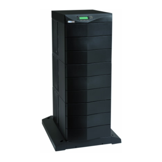
INTRODUCTION Physical Features The Eaton 9170+ UPS is available in four cabinet sizes. Figure 1 through Figure 6 show the 3-slot and 9-slot configurations and identify basic Eaton 9170+ system features. Six-slot and 12-slot cabinets are also available; external battery cabinets are available in 6-, 9-, and 12-slot sizes. - Page 12 INTRODUCTION Front Panel Display Front Cover Cabinet Base Figure 3. Nine-Slot Cabinet (Front View) 164201393 Rev E www.eaton.com/powerquality Eaton 9170 UPS (3–18 kVA) User's Guide...
- Page 13 Figure 4. Nine-Slot Cabinet (Rear View) Handle/Latch Handle Release Thumbscrew Insertion/Extraction Cams Figure 5. Power Module (ASY-0673 and ASY-0674) Secondary Stop Release Latch Release Figure 6. Battery Module (ASY-0529) 164201393 Rev E www.eaton.com/powerquality Eaton 9170 UPS (3–18 kVA) User's Guide...
- Page 14 INTRODUCTION 164201393 Rev E www.eaton.com/powerquality Eaton 9170 UPS (3–18 kVA) User's Guide...
-
Page 15: Installation Setup
Chapter 2 Installation Setup This chapter explains how to set up and install the Eaton 9170+ cabinets: Setup, including clearances and location requirements Caster cart installation (for 3- and 6-slot cabinets) Stabilizer bracket installation (for 12-slot cabinets) Rack-mount installation (for 3- and 6-slot cabinets) -
Page 16: Location Requirements
(LTS-1724) packed inside the UPS shipping carton. NOTE Verify that all Eaton 9170+ UPS power modules are the proper type for the UPS cabinet: Split-phase power modules have brown labels; universal (single-phase) power modules have black labels. Do not mix brown and black modules in the same UPS cabinet. -
Page 17: Nine- And Twelve-Slot Cabinets
If an optional floor anchor kit is included for extra stability, see ”Floor Anchor Kit Installation” on page 16 to install the floor anchor brackets. 164201393 Rev E www.eaton.com/powerquality Eaton 9170 UPS (3–18 kVA) User's Guide... -
Page 18: Caster Cart Installation (Three- And Six-Slot Cabinets)
Caster Cart Figure 7. Three-Slot Cabinet Being Lowered onto Caster Cart 164201393 Rev E www.eaton.com/powerquality Eaton 9170 UPS (3–18 kVA) User's Guide... -
Page 19: Stabilizer Bracket Installation (Twelve-Slot Cabinet Only)
Stabilizer Bracket Installation (Twelve-Slot Cabinet Only) The 12-slot Eaton 9170+ UPS cabinet is shipped with two stabilizer brackets. These brackets must be attached to the wall or the floor behind the UPS cabinet. Under all module-loading conditions, they act as a protective stop to prevent the cabinet from falling forward if it is unintentionally pushed away from the wall. -
Page 20: Rack-Mount Installation (Three- And Six-Slot Cabinets)
Set the cover aside. Remove the two cabinet side covers (four covers in 6-slot cabinets) by lifting the top edge. No other hardware must be detached. Store or discard the side covers. 164201393 Rev E www.eaton.com/powerquality Eaton 9170 UPS (3–18 kVA) User's Guide... - Page 21 UPS cabinet side frame. Using three 1/4-20 1/2” Phillips-head bolts, screw the bolts into the metal clip nuts installed in Step 4. Rack-Mount Ear Figure 10. Rack-Mount Ear Installed 164201393 Rev E www.eaton.com/powerquality Eaton 9170 UPS (3–18 kVA) User's Guide...
-
Page 22: Floor Anchor Kit Installation
Floor Anchor Kit Installation An optional floor anchor kit (ASY-0548) is available for all sizes of the Eaton 9170+ UPS. The kit helps to stabilize the UPS or battery cabinet in the event of accidental bumps or small floor movements. Any testing to specific seismic requirements is the responsibility of the customer. -
Page 23: Moving The Cabinets
C A U T I O N Do NOT attempt to raise the cabinet with the power or battery modules installed. The Eaton 9170+ UPS and the battery cabinet are very heavy with power and battery modules installed. Before moving the cabinets, remove the power and battery modules. - Page 24 After properly positioning and leveling the cabinet, insert power and battery modules into the cabinet as described in “Power and Battery Module Installation” on page 67. 164201393 Rev E www.eaton.com/powerquality Eaton 9170 UPS (3–18 kVA) User's Guide...
-
Page 25: Ups With Bypass Electrical Installation
Only qualified service personnel (such as a licensed electrician) should perform the electrical installation. Risk of electrical shock. The Eaton 9170+ UPS input power may be hardwired through conduit to either a main power source circuit breaker or to an optional external bypass switch. - Page 26 External Bypass Switch Service Line Building Load Service Distribution Panel Panel Service Line Service Line User-Supplied (if required) External Batteries (optional) Figure 12. Typical Installation with a Bypass Switch 164201393 Rev E www.eaton.com/powerquality Eaton 9170 UPS (3–18 kVA) User's Guide...
-
Page 27: Input Current Ratings
C A U T I O N To accommodate the feature of easy system expandability, it is recommended that initial installation of the Eaton 9170+ UPS contains wiring to support the maximum capacity of the UPS cabinet: 3 kVA for 3-slot cabinets; 9 kVA for 6-slot cabinets;... -
Page 28: Bypass Switches
If you turn a BBM switch from UPS to LINE, the switch disconnects the load from UPS output power before connecting the load to AC input power. The bypass switch has four positions as described in Table 3. 164201393 Rev E www.eaton.com/powerquality Eaton 9170 UPS (3–18 kVA) User's Guide... -
Page 29: Bypass Switch Operation
When the red button is pressed the UPS front panel displays “Manual Bypass.” The load position handle can now be turned from the UPS to LINE position or from the LINE to UPS position. 164201393 Rev E www.eaton.com/powerquality Eaton 9170 UPS (3–18 kVA) User's Guide... - Page 30 UPS WITH BYPASS ELECTRICAL INSTALLATION After turning the load position handle to the UPS position and releasing the red button, the Eaton 9170+ UPS remains in Bypass mode. For proper operation, return the UPS to Auto mode using the following procedure.
- Page 31 (31 lb) BPE20BBM1A BPE20MBB1A 125A/300 Vac 53.4 cm 35.6 cm 17.2 cm 28.0 cm 50.8 cm 15.9 kg (21.0”) (14.0”) (6.8”) (11.0”) (20.0”) (35 lb) Figure 13. Bypass Switch Dimensions 164201393 Rev E www.eaton.com/powerquality Eaton 9170 UPS (3–18 kVA) User's Guide...
-
Page 32: Ups Installation With An External Bypass Switch
Risk of electrical shock. C A U T I O N To prevent electrical shock or damage to the equipment, verify that the Eaton 9170+ UPS is OFF before you remove the entrance panel. The circuit breaker or disconnect switch must also be off at the AC input service panel. - Page 33 Input Signal Entrance Panel Battery Cable Figure 14. UPS Power Entrance Panel (Nine-Slot Cabinet Shown) Remove the knockouts in the entrance panel for AC input and AC output wiring. 164201393 Rev E www.eaton.com/powerquality Eaton 9170 UPS (3–18 kVA) User's Guide...
- Page 34 UPS output circuits must be installed in dedicated conduit systems and not shared with other electrical circuits. Figure 15 shows input and output wiring terminals inside the Eaton 9170+ UPS cabinet. Backplane Board Terminating Studs Figure 15.
- Page 35 Figure 16. Bypass Switch Wiring Label After installing bypass switch wiring, torque the screws holding all input and output power conductors to the values specified in Table 2 on page 22. 164201393 Rev E www.eaton.com/powerquality Eaton 9170 UPS (3–18 kVA) User's Guide...
- Page 36 (supplied in the accessory kit) may be installed on the proper terminating studs. Wires may also be terminated with ring terminals, which are attached to the output terminating studs. 164201393 Rev E www.eaton.com/powerquality Eaton 9170 UPS (3–18 kVA) User's Guide...
- Page 37 4 2 4 for the required output voltage as shown in the wiring configuration drawings. NOTE For Eaton 9170+ UPS models with low-voltage hardwire output, it is recommended to divide the total load as equally as possible between X1 and X2, as shown in Figure 18.
- Page 38 Generator On (normally open) Signal Common Plastic Cable Tie Emergency Power-off (normally closed) External Bypass *(short to common when active) Figure 20. Input Control Signal Wiring (for MBB Bypass Switch) 164201393 Rev E www.eaton.com/powerquality Eaton 9170 UPS (3–18 kVA) User's Guide...
- Page 39 EPO switch type.) 17. When all connections have been made and checked, reinstall the bypass switch front cover and UPS cabinet rear covers using the original screws. 164201393 Rev E www.eaton.com/powerquality Eaton 9170 UPS (3–18 kVA) User's Guide...
-
Page 40: System Wiring Diagrams
30 page 31 page 37 Figure 17b on Figure 19 on Figure 24 on L1 – N page 30 page 31 page 38 * Split-phase power modules required. 164201393 Rev E www.eaton.com/powerquality Eaton 9170 UPS (3–18 kVA) User's Guide... - Page 41 NOTE 6 External UPS battery cabinets are optional. See “Battery Cabinet Installation” on page 61 for installation instructions. NOTE 7 UPS output circuits shall be installed in dedicated conduit systems and not shared with other electrical circuits. 164201393 Rev E www.eaton.com/powerquality Eaton 9170 UPS (3–18 kVA) User's Guide...
- Page 42 127/220 Input, 127/220 Output Figure 22. External Bypass Switch (L1, L2, N), Split-Phase Power Modules NOTE To use Figure 22, refer to the list of Notes on page 35. 164201393 Rev E www.eaton.com/powerquality Eaton 9170 UPS (3–18 kVA) User's Guide...
- Page 43 230 Input, 230 Output 240 Input, 240 Output Figure 23. External Bypass Switch (L1, L2), Universal Power Modules NOTE To use Figure 23, refer to the list of Notes on page 35. 164201393 Rev E www.eaton.com/powerquality Eaton 9170 UPS (3–18 kVA) User's Guide...
- Page 44 230 Input, 230 Output 240 Input, 240 Output Figure 24. External Bypass Switch (L1, N), Universal Power Modules NOTE To use Figure 24, refer to the list of Notes on page 35. 164201393 Rev E www.eaton.com/powerquality Eaton 9170 UPS (3–18 kVA) User's Guide...
-
Page 45: Ups Electrical Installation
UPS. Without a bypass switch, power to the load cannot be maintained if the UPS is taken completely offline. Building Load Service Distribution Panel Panel User-Supplied External Batteries (if required) (optional) Figure 25. Typical Installation without a Bypass Switch 164201393 Rev E www.eaton.com/powerquality Eaton 9170 UPS (3–18 kVA) User's Guide... -
Page 46: Input Current Ratings
NOTE To accommodate the feature of easy system expandability, it is recommended that initial installation of the Eaton 9170+ UPS contains wiring to support the maximum capacity of the UPS cabinet: 3 kVA for 3-slot cabinets; 9 kVA for 6-slot cabinets; 18 kVA for 9- and 12-slot cabinets. - Page 47 (ampacity) wire. Code may require a larger AWG size than shown in this table because of temperature, number of conductors in the conduit, or long service runs. Follow local code requirements. 164201393 Rev E www.eaton.com/powerquality Eaton 9170 UPS (3–18 kVA) User's Guide...
-
Page 48: Ups Electrical Installation
Risk of electrical shock. C A U T I O N To prevent electrical shock or damage to the equipment, verify that the Eaton 9170+ UPS is OFF before you remove the entrance panel. The circuit breaker or disconnect switch must also be OFF at the AC input service panel. - Page 49 Input Signal Entrance Panel Battery Cable Figure 26. UPS Power Entrance Panel (Nine-Slot Cabinet Shown) Remove the knockouts in the entrance panel for AC input and AC output wiring. 164201393 Rev E www.eaton.com/powerquality Eaton 9170 UPS (3–18 kVA) User's Guide...
- Page 50 UPS output circuits must be installed in dedicated conduit systems and not shared with other electrical circuits. Figure 27 shows input and output wiring terminals inside the Eaton 9170+ UPS cabinet. Backplane Board Terminating Studs Figure 27.
- Page 51 Compression lugs (supplied in the accessory kit) may be installed on the proper terminating studs. Wires may also be terminated with ring terminals, which are attached to the output terminating studs. 164201393 Rev E www.eaton.com/powerquality Eaton 9170 UPS (3–18 kVA) User's Guide...
- Page 52 4 2 4 for the required output voltage as shown in the wiring configuration drawings. NOTE For Eaton 9170+ UPS models with low-voltage hardwire output, it is recommended to divide the total load as equally as possible between X1 and X2, as shown in Figure 29.
- Page 53 83 for information about accessing menu 4 3 2 to view or change the EPO switch type.) 11. When all connections have been made and checked, reinstall the UPS cabinet rear covers using the original screws. 164201393 Rev E www.eaton.com/powerquality Eaton 9170 UPS (3–18 kVA) User's Guide...
-
Page 54: System Wiring Diagrams
45 page 46 page 51 Figure 28b on Figure 30 on Figure 34 on L1 – N page 45 page 46 page 52 * Split-phase power modules required. 164201393 Rev E www.eaton.com/powerquality Eaton 9170 UPS (3–18 kVA) User's Guide... - Page 55 NOTE 5 External UPS battery cabinets are optional. See “Battery Cabinet Installation” on page 61 for installation instructions. NOTE 6 UPS output circuits shall be installed in dedicated conduit systems and not shared with other electrical circuits. 164201393 Rev E www.eaton.com/powerquality Eaton 9170 UPS (3–18 kVA) User's Guide...
- Page 56 127/220 Input, 127/220 Output Figure 32. No External Bypass (L1, L2, N), Split-Phase Power Modules NOTE To use Figure 32, refer to the list of Notes on page 49. 164201393 Rev E www.eaton.com/powerquality Eaton 9170 UPS (3–18 kVA) User's Guide...
- Page 57 230 Input, 230 Output 240 Input, 240 Output Figure 33. No External Bypass (L1, L2), Universal Power Modules NOTE To use Figure 33, refer to the list of Notes on page 49. 164201393 Rev E www.eaton.com/powerquality Eaton 9170 UPS (3–18 kVA) User's Guide...
- Page 58 230 Input, 230 Output 240 Input, 240 Output Figure 34. No External Bypass (L1, N), Universal Power Modules NOTE To use Figure 34, refer to the list of Notes on page 49. 164201393 Rev E www.eaton.com/powerquality Eaton 9170 UPS (3–18 kVA) User's Guide...
-
Page 59: Isolated Output Wiring Diagrams
NOTE This chapter is only for units manufactured before 2009. The wiring diagrams in this section are unique and specific to installations in which the output of the Eaton 9170+ UPS is galvanically isolated from the input. Figure 35 and Figure 36 describe output wiring configurations for various output voltages. -
Page 60: Neutral-To-Ground Bonding For Isolated Output
Figure 37. The other end of the wire (as shown by * in Figure 37) must be attached to the proper output neutral terminal, as specified in Figure 35 and Figure 36. 164201393 Rev E www.eaton.com/powerquality Eaton 9170 UPS (3–18 kVA) User's Guide... - Page 61 Ground terminations, inside the UPS rear cover, are located directly below the line input terminals. Figure 15 on page 28 shows input and output wiring terminals inside the Eaton 9170+ UPS cabinet. If there is any question as to the need for this bond wire, contact your local regulatory agency or your service representative.
-
Page 62: System Wiring Diagrams
NOTE 10 Do not connect output wiring to X1 when connecting L1 to X3. X1 produces only 88V at 208V nominal output, and 93V at 220V. 164201393 Rev E www.eaton.com/powerquality Eaton 9170 UPS (3–18 kVA) User's Guide... - Page 63 120/240 Input, 120/240 Output Figure 38. External Bypass Switch (L1, L2, N), Isolated Output for Single-Phase Voltages NOTE To use Figure 38, refer to the list of Notes on page 56. 164201393 Rev E www.eaton.com/powerquality Eaton 9170 UPS (3–18 kVA) User's Guide...
- Page 64 120/240 Input, 120/240 Output Figure 39. No External Bypass (L1, L2, N), Isolated Output for Single-Phase Voltages NOTE To use Figure 39, refer to the list of Notes on page 56. 164201393 Rev E www.eaton.com/powerquality Eaton 9170 UPS (3–18 kVA) User's Guide...
- Page 65 (Voltages require the bypass switch to be BBM; contact your service representative for details.) Figure 40. External Bypass Switch (L1, L2, N), Isolated Output for Derived Three-Phase Voltages NOTE To use Figure 40, refer to the list of Notes on page 56. 164201393 Rev E www.eaton.com/powerquality Eaton 9170 UPS (3–18 kVA) User's Guide...
- Page 66 127/220 Input, 127/220 Output Figure 41. No External Bypass (L1, L2, N), Isolated Output for Derived Three-Phase Voltages NOTE To use Figure 41, refer to the list of Notes on page 56. 164201393 Rev E www.eaton.com/powerquality Eaton 9170 UPS (3–18 kVA) User's Guide...
-
Page 67: Battery Cabinet Installation
Open the carton containing the external battery cabinet cable assembly. Locate the 3-slot section in the UPS cabinet that contains the power entrance panel. Unscrew and remove the rear panel of this section (see Figure 42). 164201393 Rev E www.eaton.com/powerquality Eaton 9170 UPS (3–18 kVA) User's Guide... - Page 68 Figure 43) until it breaks away. Figure 43. Breakaway Panel Links Verify all hazardous voltages have been removed from the backplane by testing with a voltmeter or other test device. 164201393 Rev E www.eaton.com/powerquality Eaton 9170 UPS (3–18 kVA) User's Guide...
- Page 69 11. Slip the terminals of the cable assembly onto the tabs of the bus-bar extension, putting the tabs between the stud block and the fuse end and between the other stud block and the cable terminal. 164201393 Rev E www.eaton.com/powerquality Eaton 9170 UPS (3–18 kVA) User's Guide...
- Page 70 16. If the battery cable will be installed in flexible or other conduit, pull the conductors through the conduit. Attach the conduit to both the UPS power entrance panel and the battery cabinet entrance panel as shown in Figure 46. 164201393 Rev E www.eaton.com/powerquality Eaton 9170 UPS (3–18 kVA) User's Guide...
- Page 71 19. Locate the daisy-chained cable on the rear of the first battery cabinet in the section below the location of the first cable assembly. Follow this procedure for connecting any additional daisy-chained battery cabinets. 164201393 Rev E www.eaton.com/powerquality Eaton 9170 UPS (3–18 kVA) User's Guide...
- Page 72 Battery Cabinet To Next Battery Cabinet Figure 47. Connecting Additional Battery Cabinets 20. Reinstall the remaining rear covers using the original screws. 21. Continue to “UPS Startup” on page 67. 164201393 Rev E www.eaton.com/powerquality Eaton 9170 UPS (3–18 kVA) User's Guide...
-
Page 73: Ups Startup
UPS is not connected to an AC supply. When AC input voltage is present, the Eaton 9170+ system can provide output voltage even though its batteries are disconnected. To confirm that there is no UPS output voltage, always disconnect all of the AC input sources and unplug all strings of internal battery modules;... - Page 74 UPS STARTUP NOTE All power modules in the Eaton 9170+ UPS cabinet must be of the same type: Split-phase power modules have brown labels; universal (single-phase) power modules have black labels. Do not mix brown and black modules in the same UPS cabinet.
-
Page 75: Startup For Plug-Receptacle Units
NOTE If the UPS has been manually set to operate in Bypass or Battery mode, change the System Control Mode Preference (menu 4 1) selection to Auto to return to normal Auto mode operation. 164201393 Rev E www.eaton.com/powerquality Eaton 9170 UPS (3–18 kVA) User's Guide... - Page 76 Failure to balance the loads may cause an overload alarm even if the full capacity of the UPS has not been reached. For Eaton 9170+ UPS models with low-voltage output receptacles, it is recommended to divide loads between upper and lower receptacles as equally as possible.
-
Page 77: Startup For Hardwired Units
At the bypass switch, press the red button and turn the switch to UPS. Remove the six screws in the bypass switch front cover and remove the cover to gain access to the terminal block for voltage measurements. 164201393 Rev E www.eaton.com/powerquality Eaton 9170 UPS (3–18 kVA) User's Guide... - Page 78 N to L1 (10 to 11*) 6 to 7* N to L2 (10 to 12*) 6 to 8* * For some installations, there is no connection at terminals 6, 8, 10, or 12. 164201393 Rev E www.eaton.com/powerquality Eaton 9170 UPS (3–18 kVA) User's Guide...
- Page 79 1/2-turn. Pull the button out to close the switch. Turn the key back counter-clockwise, and remove the key. 164201393 Rev E www.eaton.com/powerquality Eaton 9170 UPS (3–18 kVA) User's Guide...
-
Page 80: Initial Startup Parameters
<- and -> on the display. To change the value of the selected digit, press the buttons. When the password shows 0377, press the button. ENTER PASSWORD Password − 0000 <− −> 164201393 Rev E www.eaton.com/powerquality Eaton 9170 UPS (3–18 kVA) User's Guide... - Page 81 (two battery modules side-by-side equals one string). Each battery string contains 7.2 ampere-hours. Enter the total value in the next startup screen. External Capacity extamphr 0028.8 <− −> 164201393 Rev E www.eaton.com/powerquality Eaton 9170 UPS (3–18 kVA) User's Guide...
- Page 82 Press the ON button on this screen to start the UPS. These configuration parameters are accessible during normal UPS operation by pressing the Config button through the front panel display. 164201393 Rev E www.eaton.com/powerquality Eaton 9170 UPS (3–18 kVA) User's Guide...
-
Page 83: Operation
Chapter 8 Operation The Eaton 9170+ UPS operates in several different modes. Normally it operates under internal control (Auto mode) to automatically protect loads connected to it. An operator can enable manual override should servicing or testing be required. Figure 52 shows the operating modes. In Auto mode, the UPS automatically switches between modes depending on line and load conditions. - Page 84 Converter before 2009) Line/Battery Internal DC Power Relay Power Bus Output Relay EMI/RFI Filter Battery Charger Battery Capacitor Bank Modules (parallel) Figure 53. Eaton 9170+ UPS Functional Block Diagram 164201393 Rev E www.eaton.com/powerquality Eaton 9170 UPS (3–18 kVA) User's Guide...
-
Page 85: Turning The Ups On
Failure to properly power down the UPS could permanently damage any installed batteries. Also, if batteries become severely discharged, the UPS might not start immediately when input power is restored. 164201393 Rev E www.eaton.com/powerquality Eaton 9170 UPS (3–18 kVA) User's Guide... -
Page 86: Front Panel Display
Menu/Escape button, for moving into and out of display menus. Also, for avoiding a change to a parameter value. Menu scroll up and down buttons. Also, for increasing/decreasing parameter value digits. Enter button, to activate/accept displayed parameter or operating mode. 164201393 Rev E www.eaton.com/powerquality Eaton 9170 UPS (3–18 kVA) User's Guide... -
Page 87: Using The Front Panel Display
Top (button B) moves to the top item in the current menu level (in this example, 1 2 1). ESC (button C) exits the current menu level (in this example, to menu 1 2). 164201393 Rev E www.eaton.com/powerquality Eaton 9170 UPS (3–18 kVA) User's Guide... - Page 88 Phase 2 Input Voltage Phase 1 Output Voltage Phase 2 Output Voltage Total System Percent Load Phase 1 Percent Load Phase 2 Percent Load Battery Voltage Estimated Battery Runtime 164201393 Rev E www.eaton.com/powerquality Eaton 9170 UPS (3–18 kVA) User's Guide...
-
Page 89: Parameters
Enter the appropriate password, if applicable, and then change the parameter value. Press the button again to save the change. To not save the change, press ESC instead of the button. 164201393 Rev E www.eaton.com/powerquality Eaton 9170 UPS (3–18 kVA) User's Guide... -
Page 90: Reading The Eaton 9170+ System Logs
OPERATION Reading the Eaton 9170+ System Logs The Eaton 9170+ system makes an entry in its logs each time it sounds an alarm or runs on battery power. This information can help in diagnosing power problems. You can display the UPS Inverter and Alarm logs on the front panel display in menu 2. -
Page 91: Alarm Log
“Slot: nn” appears in the upper right hand corner, as shown in Figure 59, indicating the slot number where the fault occurred. 2 2 6 Slot: 02/05 17:51 00:01 Open Cell Slot Figure 59. Alarm Entry for Specific Slot Number 164201393 Rev E www.eaton.com/powerquality Eaton 9170 UPS (3–18 kVA) User's Guide... -
Page 92: Battery Test
To initiate a manual test, select menu 3 1 1. Use menu 3 1 to set the battery test parameters, including the test interval and time of day. During the battery test, the Eaton 9170+ performs an open cell test and displays the message “Open Cell Test” (firmware versions 2.22 and later) or “Open Cell”... -
Page 93: Menu Map
OPERATION Menu Map Figure 60 shows all the Eaton 9170+ system parameters. The menu structure has six primary-level menus, System Status Menu (1) through Service Menu (6). Each primary menu has secondary items numbered by their location under the primary menu. Use the various buttons as shown in the map to navigate to the desired parameter. - Page 94 5 1 Time 5 2 Date (ESC) 5 3 Model Name 5 4 Serial Number 5 5 Software Version 6 Service Menu (Top) Figure 60. Eaton 9170+ System Menu Map 164201393 Rev E www.eaton.com/powerquality Eaton 9170 UPS (3–18 kVA) User's Guide...
-
Page 95: Communication
Eaton provides several comprehensive power monitoring/management software products and UPS load protection software products. Each Eaton 9170+ UPS ships with a CD containing several of the software products. Visit www.eaton.com/pq/software for the latest updates to the products on the CD as well as any new power monitoring/management and protection software products. -
Page 96: Connectupst Web/Snmp Card (Bd Model)
Opening this connection creates an immediate shutdown of the Eaton 9170+ UPS output. Bypass: The signal from an external bypass switch, to isolate the Eaton 9170+ system for maintenance purposes, tells the UPS to go into Internal Bypass mode. - Page 97 These parameters are also available to trained service personnel through the Service Menu. See Figure 14 on page 27 and Figure 21 on page 33 to make the connection for all dedicated input signals. 164201393 Rev E www.eaton.com/powerquality Eaton 9170 UPS (3–18 kVA) User's Guide...
-
Page 98: Db-9 Communication Port
COMMUNICATION DB-9 Communication Port Table 13 explains the functions of the pins on the Eaton 9170+ DB-9 communication port. This port is on the Eaton 9170+ UPS rear panel, as shown in Figure 49 on page 69. Table 13. DB-9 Port Signals... -
Page 99: Maintenance
Maintenance Routine Maintenance NOTE Observe important safety precautions while performing these checks. NOTE Eaton recommends that you schedule preventive maintenance checks at least every six months. The Eaton 9170+ system is designed to provide years of trouble-free operation. Its internal control system checks the batteries and inverter periodically to ensure reliable operation. -
Page 100: Storage Temperature
The Eaton 9170+ hot‐swappable feature lets you replace the battery modules without disconnecting the load or damaging the batteries. NOTE The Eaton 9170+ UPS will operate with uncharged (or no) batteries, but will have limited (or no) battery backup capability. Backup protection requires at least three battery strings for every four power modules. -
Page 101: Power Module Replacement
Check the batteries in the slot indicated on the alarm screen. Power Module Replacement The Eaton 9170+ hot‐swap feature lets you replace a power module without disconnecting the load or damaging the UPS. NOTE The UPS may switch to internal Bypass mode if the remaining power modules are insufficient to supply the required power. - Page 102 Raise the power module handle to secure the module into the cabinet. Be sure the handle latch snaps into place. Tighten the thumbscrew on the handle. Replace the front cover. 164201393 Rev E www.eaton.com/powerquality Eaton 9170 UPS (3–18 kVA) User's Guide...
-
Page 103: Specifications
Chapter 11 Specifications This section provides the following specifications for the Eaton 9170+ models: Electrical input and output Model specifications Environmental and safety Battery Weights and dimensions Table 14. Electrical Input and Output Nominal Input Voltage 200–240 Vac or 100/200, 110/220, 120/208, 120/240, 127/220 Vac Input Voltage Range 176–276 Vac*... - Page 104 For redundant power module operation (N+X), increase the input current rating by 2A for each additional redundant power module. ** Maximum current rating for the cabinet size. If an additional charger is desired, it must be installed in external battery cabinet XXXXX-Model/Batt4. 164201393 Rev E www.eaton.com/powerquality Eaton 9170 UPS (3–18 kVA) User's Guide...
- Page 105 For redundant power module operation (N+X), increase the input current rating by 2A for each additional redundant power module. ** Maximum current rating for the cabinet size. If an additional charger is desired, it must be installed in external battery cabinet XXXXX-Model/Batt4. 164201393 Rev E www.eaton.com/powerquality Eaton 9170 UPS (3–18 kVA) User's Guide...
- Page 106 For redundant power module operation (N+X), increase the input current rating by 2A for each additional redundant power module. ** Maximum current rating for the cabinet size. If an additional charger is desired, it must be installed in external battery cabinet XXXXX-Model/Batt4. 164201393 Rev E www.eaton.com/powerquality Eaton 9170 UPS (3–18 kVA) User's Guide...
- Page 107 For redundant power module operation (N+X), increase the input current rating by 2A for each additional redundant power module. ** Maximum current rating for the cabinet size. If an additional charger is desired, it must be installed in external battery cabinet XXXXX-Model/Batt4. 164201393 Rev E www.eaton.com/powerquality Eaton 9170 UPS (3–18 kVA) User's Guide...
- Page 108 For redundant power module operation (N+X), increase the input current rating by 2A for each additional redundant power module. ** Maximum current rating for the cabinet size. If an additional charger is desired, it must be installed in external battery cabinet XXXXX-Model/Batt4. 164201393 Rev E www.eaton.com/powerquality Eaton 9170 UPS (3–18 kVA) User's Guide...
- Page 109 For redundant power module operation (N+X), increase the input current rating by 2A for each additional redundant power module. ** Maximum current rating for the cabinet size. If an additional charger is desired, it must be installed in external battery cabinet XXXXX-Model/Batt4. 164201393 Rev E www.eaton.com/powerquality Eaton 9170 UPS (3–18 kVA) User's Guide...
- Page 110 The air around the UPS must be clean and free of dust, corrosive chemicals, and other contaminants. The Eaton 9170+ UPS uses internal fans to circulate the air for cooling. The air must be free to circulate around the UPS and battery cabinet(s). Do not operate the UPS in a sealed room or container.
- Page 111 89 kg (196 lb) S Optional floor anchor kit weighs 4 kg (9 lb) S Each battery module weighs 14 kg (30 lb) S Each power module weighs 8 kg (17 lb) 164201393 Rev E www.eaton.com/powerquality Eaton 9170 UPS (3–18 kVA) User's Guide...
- Page 112 SPECIFICATIONS 164201393 Rev E www.eaton.com/powerquality Eaton 9170 UPS (3–18 kVA) User's Guide...
-
Page 113: Troubleshooting
Go to menus 1 1 2 and 1 1 3 for the input voltage; go to menus 1 2 2 and 1 2 3 for the voltage? output voltage. Check the battery voltage? Go to menu 1 3 1. To view other system status parameters, see the Menu map on page 88. 164201393 Rev E www.eaton.com/powerquality Eaton 9170 UPS (3–18 kVA) User's Guide... - Page 114 Set the UPS to operate in The Eaton 9170+ system will not change operating modes as a timed event. But, if you High Efficiency mode on wish to conserve energy, before leaving for the weekend, go to menu 4 1. Select High...
-
Page 115: Alarms
(Silence) (Clear) (ESC) Figure 62. Detailed Alarm Entry When the Eaton 9170+ UPS detects an alarm condition, the UPS displays the alarm with the following indications: Illuminates the red LED next to the front panel display Sounds an audible alarm Displays an alarm message 164201393 Rev E www.eaton.com/powerquality... - Page 116 If the UPS has not shut down, bypass the UPS or shut Temperature If the temperature reaches a preset down your equipment, and turn the UPS off. Contact limit, the unit will shut down. your service representative. 164201393 Rev E www.eaton.com/powerquality Eaton 9170 UPS (3–18 kVA) User's Guide...
- Page 117 Contact your service Incompatible Module system. representative. 5 Fan Failure The UPS has detected a module fan Contact your service representative. problem that requires service. 164201393 Rev E www.eaton.com/powerquality Eaton 9170 UPS (3–18 kVA) User's Guide...
- Page 118 Reduce the load or install additional power too few to provide the programmed modules. Insufficient redundancy level while protecting the Modules load. The UPS will protect the load, but will not be fault tolerant. 164201393 Rev E www.eaton.com/powerquality Eaton 9170 UPS (3–18 kVA) User's Guide...
-
Page 119: Service And Support
TROUBLESHOOTING Service and Support If you have any questions or problems with the UPS, call your Local Distributor or the Eaton Customer Support Center at one of the following telephone numbers. Available Support Services: Onsite Service Technician scheduling Technical product information or troubleshooting... - Page 120 TROUBLESHOOTING 164201393 Rev E www.eaton.com/powerquality Eaton 9170 UPS (3–18 kVA) User's Guide...
-
Page 121: Warranty
Eaton UPS Models: 9155, 9170+ and FERRUPS 4.3–18 kVA ® WARRANTOR: The warrantor for the limited warranties set forth herein is Eaton Corporation Corporation, an Ohio Corporation company (“Company”). LIMITED WARRANTY: This limited warranty (this “Warranty”) applies only to the original End-User (the “End-User”) of any Eaton 9155, 9170+, and FERRUPS 4.3–18 kVA Products (individually and collectively, the “Product”) - Page 122 In order to receive the benefits of this Warranty, the End-User must use the Product in a normal way; follow the Product's user's guide; and protect against further damage to the Product if there is a covered defect. 164201393 Rev E www.eaton.com/powerquality Eaton 9170 UPS (3–18 kVA) User's Guide...
-
Page 123: Load Protection Guarantee (Us And Canada)
In the USA, call the Customer Reliability Center 7x24 at 800-356-5737. Outside of the USA, contact your local Eaton product sales or service representative. For comments or questions about this Warranty, write to the Customer Quality Representative, 3301 Spring Forest Road, Raleigh, North Carolina 27616 USA. - Page 124 In the USA, call the Customer Reliability Center 7x24 at 800-356-5737. Outside of the USA, contact your local Eaton product sales or service representative. For comments or questions about this Load Protection Guaranty, write to the Customer Quality Representative, 3301 Spring Forest Road, Raleigh, North Carolina 27616 USA.
Need help?
Do you have a question about the Powerware 9170+ UPS 3–18 kVA and is the answer not in the manual?
Questions and answers