Eaton Powerware 9170+ User Manual
3–18 kva
Hide thumbs
Also See for Powerware 9170+:
- Flashing procedure (14 pages) ,
- Installation manual (12 pages) ,
- User manual (124 pages)
Table of Contents
Advertisement
Quick Links
Advertisement
Table of Contents

Related Manuals for Eaton Powerware 9170+


Summary of Contents for Eaton Powerware 9170+
- Page 1 Powerware 9170 ® 3–18 kVA User’s Guide...
- Page 2 Eaton Power Quality Corporation. Torx is a registered trademark of Textron, Inc. ECopyright 2000–2006 Eaton Corporation, Raleigh, NC, USA. All rights reserved. No part of this document may be reproduced in any way without the express written approval of Eaton Corporation.
- Page 3 Class A EMC Statements FCC Part 15 This equipment has been tested and found to comply with the limits for a Class A digital device, pursuant to NOTE part 15 of the FCC Rules. These limits are designed to provide reasonable protection against harmful interference when the equipment is operated in a commercial environment.
- Page 4 Special Symbols The following are examples of symbols used on the UPS or accessories to alert you to important information: RISK OF ELECTRIC SHOCK - Indicates that a risk of electric shock is present and the associated warning should be observed. CAUTION: REFER TO OPERATOR’S MANUAL - Refer to your operator’s manual for additional information, such as important operating and maintenance instructions.
-
Page 5: Table Of Contents
............® EATON Powerware 9170 UPS (3–18 kVA) User’s Guide... - Page 6 ..........® EATON Powerware 9170 UPS (3–18 kVA) User’s Guide...
-
Page 7: Introduction
To permit UPS removal from the power path while maintaining power to the loads, an external bypass switch is required. This switch is optional but recommended for system serviceability. ® EATON Powerware 9170 UPS (3–18 kVA) User’s Guide 164201393 Rev C www.powerware.com... -
Page 8: Safety Warnings
These must be within sight of the UPS and easily accessible. For a plug-receptacle unit, the plug serves as the power input disconnect device, which must also be readily accessible. ® EATON Powerware 9170 UPS (3–18 kVA) User’s Guide 164201393 Rev C www.powerware.com... - Page 9 Ceux-ci doivent se trouver dans le périmètre de l’onduleur et être faciles d’accès. En ce qui concerne l’unité de prise, la prise sert d’appareil de déconnexion de l’alimentation en entrée, laquelle doit également être facile d’accès. ® EATON Powerware 9170 UPS (3–18 kVA) User’s Guide 164201393 Rev C www.powerware.com...
-
Page 10: Advertencias De Seguridad
SIE. Éstos deben estar a la vista del SIE y ser de fácil acceso. Para una unidad con receptáculo de conexión, el conector funge como dispositivo de desconexión de entrada de alimentación, el cual también debe estar fácilmente accesible. ® EATON Powerware 9170 UPS (3–18 kVA) User’s Guide 164201393 Rev C www.powerware.com... -
Page 11: Physical Features
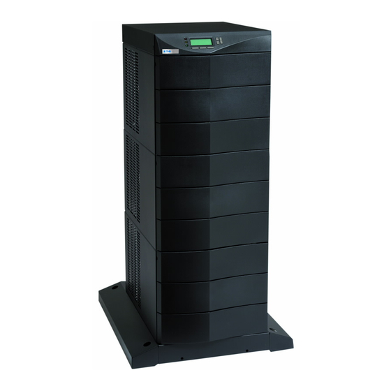
Display Front Cover Figure 1. Three-Slot Cabinet (Front View) Communication DB-9 Slots Communication Port Power Outlets (optional) Input Power Cable (optional) Figure 2. Three-Slot Cabinet (Rear View) ® EATON Powerware 9170 UPS (3–18 kVA) User’s Guide 164201393 Rev C www.powerware.com... - Page 12 INTRODUCTION Front Panel Display Front Cover Cabinet Base Figure 3. Nine-Slot Cabinet (Front View) ® EATON Powerware 9170 UPS (3–18 kVA) User’s Guide 164201393 Rev C www.powerware.com...
- Page 13 Figure 4. Nine-Slot Cabinet (Rear View) Handle/Latch Handle Release Thumbscrew Insertion/Extraction Cams Figure 5. Power Module (ASY-0673 and ASY-0674) Secondary Stop Release Latch Release Figure 6. Battery Module (ASY-0529) ® EATON Powerware 9170 UPS (3–18 kVA) User’s Guide 164201393 Rev C www.powerware.com...
- Page 14 INTRODUCTION ® EATON Powerware 9170 UPS (3–18 kVA) User’s Guide 164201393 Rev C www.powerware.com...
-
Page 15: Installation Setup
Nine- and 12-slot external battery cabinets may be installed with bases tight against the UPS cabinet base and against each other. Six-slot cabinets require 15.2 cm (6”) of separation. ® EATON Powerware 9170 UPS (3–18 kVA) User’s Guide 164201393 Rev C www.powerware.com... -
Page 16: Location Requirements
Cut the lifting straps or slip them off the cabinet base tabs. If an optional floor anchor kit is included for extra stability, see ”Floor Anchor Kit Installation” on page 16 to install the floor anchor brackets. ® EATON Powerware 9170 UPS (3–18 kVA) User’s Guide 164201393 Rev C www.powerware.com... -
Page 17: Nine- And Twelve-Slot Cabinets
If an optional floor anchor kit is included for extra stability, see ”Floor Anchor Kit Installation” on page 16 to install the floor anchor brackets. ® EATON Powerware 9170 UPS (3–18 kVA) User’s Guide 164201393 Rev C www.powerware.com... -
Page 18: Caster Cart Installation (Three- And Six-Slot Cabinets)
Caster Cart Figure 7. Three-Slot Cabinet Being Lowered onto Caster Cart ® EATON Powerware 9170 UPS (3–18 kVA) User’s Guide 164201393 Rev C www.powerware.com... -
Page 19: Stabilizer Bracket Installation (Twelve-Slot Cabinet Only)
Roll the UPS cabinet to its intended location. Position the rear section of the cabinet base under the open ends of the stabilizer brackets as far as the cabinet will go. ® EATON Powerware 9170 UPS (3–18 kVA) User’s Guide 164201393 Rev C www.powerware.com... -
Page 20: Rack-Mount Installation (Three- And Six-Slot Cabinets)
Remove the two cabinet side covers (four covers in 6-slot cabinets) by lifting the top edge. No other hardware must be detached. Store or discard the side covers. ® EATON Powerware 9170 UPS (3–18 kVA) User’s Guide 164201393 Rev C www.powerware.com... - Page 21 1/2” Phillips-head bolts, screw the bolts into the metal clip nuts installed in Step 4. Rack-Mount Ear Figure 10. Rack-Mount Ear Installed Select the position for the UPS in the equipment rack. ® EATON Powerware 9170 UPS (3–18 kVA) User’s Guide 164201393 Rev C www.powerware.com...
-
Page 22: Floor Anchor Kit Installation
® EATON Powerware 9170 UPS (3–18 kVA) User’s Guide 164201393 Rev C www.powerware.com... -
Page 23: Moving The Cabinets
“Caster Cart Installation (Three- and Six-Slot Cabinets)” on page 12 describes how to set the four foot pads on this cart to keep the cabinet from rolling when properly positioned. ® EATON Powerware 9170 UPS (3–18 kVA) User’s Guide 164201393 Rev C www.powerware.com... - Page 24 After properly positioning and leveling the cabinet, insert power and battery modules into the cabinet as described in “Power and Battery Module Installation” on page 68. ® EATON Powerware 9170 UPS (3–18 kVA) User’s Guide 164201393 Rev C www.powerware.com...
-
Page 25: Ups With Bypass Electrical Installation
UPS downtime. If a bypass switch is used, both UPS input and UPS output must be hardwired — through separate conduits — to the bypass switch, as shown in Figure 13. ® EATON Powerware 9170 UPS (3–18 kVA) User’s Guide 164201393 Rev C www.powerware.com... - Page 26 External Bypass Switch Service Line Building Load Service Distribution Panel Panel Service Line Service Line User-Supplied (if required) External Batteries (optional) Figure 13. Typical Installation with a Bypass Switch ® EATON Powerware 9170 UPS (3–18 kVA) User’s Guide 164201393 Rev C www.powerware.com...
-
Page 27: Input Current Ratings
UPS contains wiring to support the maximum capacity of the UPS cabinet: 3 kVA for 3-slot cabinets; 9 kVA for 6-slot cabinets; 18 kVA for 9- and 12-slot cabinets. ® EATON Powerware 9170 UPS (3–18 kVA) User’s Guide 164201393 Rev C www.powerware.com... -
Page 28: Bypass Switches
If you turn a BBM switch from UPS to LINE, the switch disconnects the load from UPS output power before connecting the load to AC input power. The bypass switch has four positions as described in Table 3. ® EATON Powerware 9170 UPS (3–18 kVA) User’s Guide 164201393 Rev C www.powerware.com... - Page 29 (11.0”) (20.0”) (31 lb) BPE20BBM1A BPE20MBB1A 125A/300 Vac 53.4 cm 35.6 cm 17.2 cm 28.0 cm 50.8 cm 15.9 kg (21.0”) (14.0”) (6.8”) (11.0”) (20.0”) (35 lb) ® EATON Powerware 9170 UPS (3–18 kVA) User’s Guide 164201393 Rev C www.powerware.com...
- Page 30 UPS WITH BYPASS ELECTRICAL INSTALLATION Figure 14. Bypass Switch Dimensions ® EATON Powerware 9170 UPS (3–18 kVA) User’s Guide 164201393 Rev C www.powerware.com...
-
Page 31: Ups Installation With An External Bypass Switch
Wiring for an optional generator input signal must pass through a separate opening. Installing this wiring is described in Steps 14 and 15 on page 32. ® EATON Powerware 9170 UPS (3–18 kVA) User’s Guide 164201393 Rev C www.powerware.com... - Page 32 Entrance Panel Battery Cable Figure 15. UPS Power Entrance Panel (Nine-Slot Cabinet Shown) Remove the knockouts in the entrance panel for AC input and AC output wiring. ® EATON Powerware 9170 UPS (3–18 kVA) User’s Guide 164201393 Rev C www.powerware.com...
- Page 33 Figure 16 shows input and output wiring terminals inside the Powerware 9170 UPS cabinet. Backplane Board Terminating Studs Figure 16. UPS Input and Output Terminals ® EATON Powerware 9170 UPS (3–18 kVA) User’s Guide 164201393 Rev C www.powerware.com...
- Page 34 Figure 17. Bypass Switch Wiring Label After installing bypass switch wiring, torque the screws holding all input and output power conductors to the values specified in Table 2 on page 22. ® EATON Powerware 9170 UPS (3–18 kVA) User’s Guide 164201393 Rev C www.powerware.com...
- Page 35 Compression lugs (supplied in the accessory kit) may be installed on the proper terminating studs. Wires may also be terminated with ring terminals, which are attached to the output terminating studs. ® EATON Powerware 9170 UPS (3–18 kVA) User’s Guide 164201393 Rev C www.powerware.com...
- Page 36 200, 208, 220, 230, or 240V Out * Menu 4 2 4 set to 200, 208, 220, 230, or 240, as required. N/-DC L2/N Figure 20. Universal Power Modules with Non-Isolated Output ® EATON Powerware 9170 UPS (3–18 kVA) User’s Guide 164201393 Rev C www.powerware.com...
- Page 37 (normally open) Signal Common Plastic Cable Tie Emergency Power-off (normally closed) External Bypass *(short to common when active) Figure 21. Input Control Signal Wiring (for MBB Bypass Switch) ® EATON Powerware 9170 UPS (3–18 kVA) User’s Guide 164201393 Rev C www.powerware.com...
- Page 38 EPO switch type.) 17. When all connections have been made and checked, reinstall the bypass switch front cover and UPS cabinet rear covers using the original screws. ® EATON Powerware 9170 UPS (3–18 kVA) User’s Guide 164201393 Rev C www.powerware.com...
-
Page 39: System Wiring Diagrams
30 page 36 Figure 18b on Figure 20 on Figure 25 on L1 – N page 29 page 30 page 37 * Split-phase power modules required. ® EATON Powerware 9170 UPS (3–18 kVA) User’s Guide 164201393 Rev C www.powerware.com... - Page 40 NOTE 6 External UPS battery cabinets are optional. See “Battery Cabinet Installation” on page 61 for installation instructions. NOTE 7 UPS output circuits shall be installed in dedicated conduit systems and not shared with other electrical circuits. ® EATON Powerware 9170 UPS (3–18 kVA) User’s Guide 164201393 Rev C www.powerware.com...
- Page 41 Figure 23. External Bypass Switch (L1, L2, N), Non-Isolated Output, Split-Phase Power Modules NOTE To use Figure 23, refer to the list of Notes on page 34. ® EATON Powerware 9170 UPS (3–18 kVA) User’s Guide 164201393 Rev C www.powerware.com...
- Page 42 240 Input, 240 Output Figure 24. External Bypass Switch (L1, L2), Non-Isolated Output, Universal Power Modules NOTE To use Figure 24, refer to the list of Notes on page 34. ® EATON Powerware 9170 UPS (3–18 kVA) User’s Guide 164201393 Rev C www.powerware.com...
- Page 43 240 Input, 240 Output Figure 25. External Bypass Switch (L1, N), Non-Isolated Output, Universal Power Modules NOTE To use Figure 25, refer to the list of Notes on page 34. ® EATON Powerware 9170 UPS (3–18 kVA) User’s Guide 164201393 Rev C www.powerware.com...
- Page 44 UPS WITH BYPASS ELECTRICAL INSTALLATION ® EATON Powerware 9170 UPS (3–18 kVA) User’s Guide 164201393 Rev C www.powerware.com...
-
Page 45: Ups Electrical Installation
UPS is taken completely offline. Building Load Service Distribution Panel Panel User-Supplied External Batteries (if required) (optional) Figure 26. Typical Installation without a Bypass Switch ® EATON Powerware 9170 UPS (3–18 kVA) User’s Guide 164201393 Rev C www.powerware.com... -
Page 46: Input Current Ratings
UPS contains wiring to support the maximum capacity of the UPS cabinet: 3 kVA for 3-slot cabinets; 9 kVA for 6-slot cabinets; 18 kVA for 9- and 12-slot cabinets. ® EATON Powerware 9170 UPS (3–18 kVA) User’s Guide 164201393 Rev C www.powerware.com... - Page 47 (ampacity) wire. Code may require a larger AWG size than shown in this table because of temperature, number of conductors in the conduit, or long service runs. Follow local code requirements. ® EATON Powerware 9170 UPS (3–18 kVA) User’s Guide 164201393 Rev C www.powerware.com...
-
Page 48: Ups Electrical Installation
Wiring for an optional generator input signal must pass through a separate opening. Installing this wiring is described in Steps 8 and 9 on page 47. ® EATON Powerware 9170 UPS (3–18 kVA) User’s Guide 164201393 Rev C www.powerware.com... - Page 49 Entrance Panel Battery Cable Figure 27. UPS Power Entrance Panel (Nine-Slot Cabinet Shown) Remove the knockouts in the entrance panel for AC input and AC output wiring. ® EATON Powerware 9170 UPS (3–18 kVA) User’s Guide 164201393 Rev C www.powerware.com...
- Page 50 Figure 28. UPS Input and Output Terminals Torque the screws holding all input and output power conductors to the values specified in Table 7 on page 41. ® EATON Powerware 9170 UPS (3–18 kVA) User’s Guide 164201393 Rev C www.powerware.com...
- Page 51 Compression lugs (supplied in the accessory kit) may be installed on the proper terminating studs. Wires may also be terminated with ring terminals, which are attached to the output terminating studs. ® EATON Powerware 9170 UPS (3–18 kVA) User’s Guide 164201393 Rev C www.powerware.com...
- Page 52 200, 208, 220, 230, or 240V Out * Menu 4 2 4 set to 200, 208, 220, 230, or 240, as required. N/-DC L2/N Figure 31. Universal Power Modules with Non-Isolated Output ® EATON Powerware 9170 UPS (3–18 kVA) User’s Guide 164201393 Rev C www.powerware.com...
- Page 53 85 for information about accessing menu 4 3 2 to view or change the EPO switch type.) 11. When all connections have been made and checked, reinstall the UPS cabinet rear covers using the original screws. ® EATON Powerware 9170 UPS (3–18 kVA) User’s Guide 164201393 Rev C www.powerware.com...
-
Page 54: System Wiring Diagrams
46 page 51 Figure 29b on Figure 31 on Figure 35 on L1 – N page 45 page 46 page 52 * Split-phase power modules required. ® EATON Powerware 9170 UPS (3–18 kVA) User’s Guide 164201393 Rev C www.powerware.com... - Page 55 NOTE 5 External UPS battery cabinets are optional. See “Battery Cabinet Installation” on page 61 for installation instructions. NOTE 6 UPS output circuits shall be installed in dedicated conduit systems and not shared with other electrical circuits. ® EATON Powerware 9170 UPS (3–18 kVA) User’s Guide 164201393 Rev C www.powerware.com...
- Page 56 Figure 33. No External Bypass (L1, L2, N), Non-Isolated Output, and Split-Phase Power Modules NOTE To use Figure 33, refer to the list of Notes on page 49. ® EATON Powerware 9170 UPS (3–18 kVA) User’s Guide 164201393 Rev C www.powerware.com...
- Page 57 Figure 34. No External Bypass (L1, L2), Non-Isolated Output, and Universal Power Modules NOTE To use Figure 34, refer to the list of Notes on page 49. ® EATON Powerware 9170 UPS (3–18 kVA) User’s Guide 164201393 Rev C www.powerware.com...
- Page 58 Figure 35. No External Bypass (L1, N), Non-Isolated Output, and Universal Power Modules NOTE To use Figure 35, refer to the list of Notes on page 49. ® EATON Powerware 9170 UPS (3–18 kVA) User’s Guide 164201393 Rev C www.powerware.com...
-
Page 59: Isolated Output Wiring Diagrams
L1, L2, N 127/220* 127/220 Figure 18a on Figure 37 on Figure 42 on page 29 page 54 page 60 * External bypass switch, if installed, must be Break-Before-Make. ® EATON Powerware 9170 UPS (3–18 kVA) User’s Guide 164201393 Rev C www.powerware.com... -
Page 60: Neutral-To-Ground Bonding For Isolated Output
Figure 38. The other end of the wire (as shown by * in Figure 38) must be attached to the proper output neutral terminal, as specified in Figure 36 and Figure 37. ® EATON Powerware 9170 UPS (3–18 kVA) User’s Guide 164201393 Rev C www.powerware.com... - Page 61 If there is any question as to the need for this bond wire, contact your local regulatory agency or your service representative. N-G Bond Wire Figure 38. N-G Bond Wire ® EATON Powerware 9170 UPS (3–18 kVA) User’s Guide 164201393 Rev C www.powerware.com...
-
Page 62: System Wiring Diagrams
NOTE 10 Do not connect output wiring to X1 when connecting L1 to X3. X1 produces only 88V at 208V nominal output, and 93V at 220V. ® EATON Powerware 9170 UPS (3–18 kVA) User’s Guide 164201393 Rev C www.powerware.com... - Page 63 Figure 39. External Bypass Switch (L1, L2, N), Isolated Output for Single-Phase Voltages NOTE To use Figure 39, refer to the list of Notes on page 56. ® EATON Powerware 9170 UPS (3–18 kVA) User’s Guide 164201393 Rev C www.powerware.com...
- Page 64 Figure 40. No External Bypass (L1, L2, N), Isolated Output for Single-Phase Voltages NOTE To use Figure 40, refer to the list of Notes on page 56. ® EATON Powerware 9170 UPS (3–18 kVA) User’s Guide 164201393 Rev C www.powerware.com...
- Page 65 Figure 41. External Bypass Switch (L1, L2, N), Isolated Output for Derived Three-Phase Voltages NOTE To use Figure 41, refer to the list of Notes on page 56. ® EATON Powerware 9170 UPS (3–18 kVA) User’s Guide 164201393 Rev C www.powerware.com...
- Page 66 Figure 42. No External Bypass (L1, L2, N), Isolated Output for Derived Three-Phase Voltages NOTE To use Figure 42, refer to the list of Notes on page 56. ® EATON Powerware 9170 UPS (3–18 kVA) User’s Guide 164201393 Rev C www.powerware.com...
-
Page 67: Battery Cabinet Installation
Locate the 3-slot section in the UPS cabinet that contains the power entrance panel. Unscrew and remove the rear panel of this section (see Figure 43). ® EATON Powerware 9170 UPS (3–18 kVA) User’s Guide 164201393 Rev C www.powerware.com... - Page 68 Figure 44) until it breaks away. Figure 44. Breakaway Panel Links Verify all hazardous voltages have been removed from the backplane by testing with a voltmeter or other test device. ® EATON Powerware 9170 UPS (3–18 kVA) User’s Guide 164201393 Rev C www.powerware.com...
- Page 69 11. Slip the terminals of the cable assembly onto the tabs of the bus-bar extension, putting the tabs between the stud block and the fuse end and between the other stud block and the cable terminal. ® EATON Powerware 9170 UPS (3–18 kVA) User’s Guide 164201393 Rev C www.powerware.com...
- Page 70 16. If the battery cable will be installed in flexible or other conduit, pull the conductors through the conduit. Attach the conduit to both the UPS power entrance panel and the battery cabinet entrance panel as shown in Figure 47. ® EATON Powerware 9170 UPS (3–18 kVA) User’s Guide 164201393 Rev C www.powerware.com...
- Page 71 19. Locate the daisy-chained cable on the rear of the first battery cabinet in the section below the location of the first cable assembly. Follow this procedure for connecting any additional daisy-chained battery cabinets. ® EATON Powerware 9170 UPS (3–18 kVA) User’s Guide 164201393 Rev C www.powerware.com...
- Page 72 To Next Battery Cabinet Figure 48. Connecting Additional Battery Cabinets 20. Reinstall the remaining rear covers using the original screws. 21. Continue to “UPS Startup” on page 67. ® EATON Powerware 9170 UPS (3–18 kVA) User’s Guide 164201393 Rev C www.powerware.com...
-
Page 73: Ups Startup
40°C (104°F). Do not operate near water or excessive humidity (95% maximum). For optimum battery life, ambient temperature should not exceed 25°C (77°F). Battery life is substantially reduced if ambient temperature is higher. ® EATON Powerware 9170 UPS (3–18 kVA) User’s Guide 164201393 Rev C www.powerware.com... -
Page 74: Power And Battery Module Installation
(see Figure 49). Raise the power module handle to secure the module into the cabinet. Be sure the handle latch snaps into place. Tighten the thumbscrew on the handle. ® EATON Powerware 9170 UPS (3–18 kVA) User’s Guide 164201393 Rev C www.powerware.com... -
Page 75: Startup For Plug-Receptacle Units
Insert the switch key supplied with the cabinet into the button and turn clockwise 1/2-turn. Pull the button out to close the switch. Turn the key back counter-clockwise, and remove the key. ® EATON Powerware 9170 UPS (3–18 kVA) User’s Guide 164201393 Rev C www.powerware.com... - Page 76 If applicable, test proper operation of optional external control signals and computer communication before connecting the load. (See “DB-9 Communication Port” on page 94 for details.) ® EATON Powerware 9170 UPS (3–18 kVA) User’s Guide 164201393 Rev C www.powerware.com...
- Page 77 3-wire plus ground input. If you have a universal power module (ASY-0674), all receptacles MUST be re-wired for a 2-wire plus ground input configuration as shown in Figure 20 on page 30. ® EATON Powerware 9170 UPS (3–18 kVA) User’s Guide 164201393 Rev C www.powerware.com...
-
Page 78: Startup For Hardwired Units
At the bypass switch, press the red button and turn the switch to UPS. Remove the six screws in the bypass switch front cover and remove the cover to gain access to the terminal block for voltage measurements. ® EATON Powerware 9170 UPS (3–18 kVA) User’s Guide 164201393 Rev C www.powerware.com... - Page 79 6 to 7* N to L2 (10 to 12*) 6 to 8* * For some installations, there is no connection at terminals 6, 8, 10, or 12. ® EATON Powerware 9170 UPS (3–18 kVA) User’s Guide 164201393 Rev C www.powerware.com...
- Page 80 1/2-turn. Pull the button out to close the switch. Turn the key back counter-clockwise, and remove the key. ® EATON Powerware 9170 UPS (3–18 kVA) User’s Guide 164201393 Rev C www.powerware.com...
-
Page 81: Initial Startup Parameters
<- and -> on the display. To change the value of the selected digit, press the buttons. When the password shows 0377, press the button. ENTER PASSWORD Password - 0000 <- -> ® EATON Powerware 9170 UPS (3–18 kVA) User’s Guide 164201393 Rev C www.powerware.com... - Page 82 Each battery string contains 7.2 ampere-hours. Enter the total value in the next startup screen. External Capacity extamphr 0028.8 <- -> ® EATON Powerware 9170 UPS (3–18 kVA) User’s Guide 164201393 Rev C www.powerware.com...
- Page 83 Press the ON button on this screen to start the UPS. These configuration parameters are accessible during normal UPS operation by pressing the Config button through the front panel display. ® EATON Powerware 9170 UPS (3–18 kVA) User’s Guide 164201393 Rev C www.powerware.com...
- Page 84 UPS STARTUP ® EATON Powerware 9170 UPS (3–18 kVA) User’s Guide 164201393 Rev C www.powerware.com...
-
Page 85: Operation
Double Conversion mode. Complete loss of input voltage causes the UPS to transfer to Battery mode. While in H.E. mode, the UPS provides passive EMI filtering in the power path. ® EATON Powerware 9170 UPS (3–18 kVA) User’s Guide 164201393 Rev C www.powerware.com... - Page 86 (optional) Line/Battery Internal DC Power Relay Power Bus Output Relay EMI/RFI Filter Battery Charger Battery Capacitor Bank Modules (parallel) Figure 54. Powerware 9170 UPS Functional Block Diagram ® EATON Powerware 9170 UPS (3–18 kVA) User’s Guide 164201393 Rev C www.powerware.com...
-
Page 87: Turning The Ups On
Failure to properly power down the UPS could permanently damage any installed batteries. Also, if batteries become severely discharged, the UPS might not start immediately when input power is restored. ® EATON Powerware 9170 UPS (3–18 kVA) User’s Guide 164201393 Rev C www.powerware.com... -
Page 88: Front Panel Display
Menu/Escape button, for moving into and out of display menus. Also, for avoiding a change to a parameter value. Menu scroll up and down buttons. Also, for increasing/decreasing parameter value digits. Enter button, to activate/accept displayed parameter or operating mode. ® EATON Powerware 9170 UPS (3–18 kVA) User’s Guide 164201393 Rev C www.powerware.com... -
Page 89: Using The Front Panel Display
Top (button B) moves to the top item in the current menu level (in this example, 1 2 1). ESC (button C) exits the current menu level (in this example, to menu 1 2). ® EATON Powerware 9170 UPS (3–18 kVA) User’s Guide 164201393 Rev C www.powerware.com... - Page 90 Phase 2 Input Voltage Phase 1 Output Voltage Phase 2 Output Voltage Total System Percent Load Phase 1 Percent Load Phase 2 Percent Load Battery Voltage Estimated Battery Runtime ® EATON Powerware 9170 UPS (3–18 kVA) User’s Guide 164201393 Rev C www.powerware.com...
-
Page 91: Parameters
Enter the appropriate password, if applicable, and then change the parameter value. Press the button again to save the change. To not save the change, press ESC instead of the button. ® EATON Powerware 9170 UPS (3–18 kVA) User’s Guide 164201393 Rev C www.powerware.com... -
Page 92: Reading The Powerware 9170+ System Logs
Line Fault UPS switched to battery because the input voltage was too high or low. Battery Test Battery test initiated inverter operation. Manual Operator initiated inverter operation. ® EATON Powerware 9170 UPS (3–18 kVA) User’s Guide 164201393 Rev C www.powerware.com... -
Page 93: Alarm Log
“Slot: nn” appears in the upper right hand corner, as shown in Figure 60, indicating the slot number where the fault occurred. 2 2 6 Slot: 02/05 17:51 00:01 Open Cell Slot Figure 60. Alarm Entry for Specific Slot Number ® EATON Powerware 9170 UPS (3–18 kVA) User’s Guide 164201393 Rev C www.powerware.com... -
Page 94: Battery Test
“Open Cell Test” (firmware versions 2.22 and later) or “Open Cell” (firmware versions prior to 2.22). Both of these messages are different from the Open Cell alarm. ® EATON Powerware 9170 UPS (3–18 kVA) User’s Guide 164201393 Rev C www.powerware.com... -
Page 95: Menu Map
Service Menu (6). Each primary menu has secondary items numbered by their location under the primary menu. Use the various buttons as shown in the map to navigate to the desired parameter. ® EATON Powerware 9170 UPS (3–18 kVA) User’s Guide 164201393 Rev C www.powerware.com... - Page 96 5 2 Date (ESC) 5 3 Model Name 5 4 Serial Number 5 5 Software Version 6 Service Menu (Top) Figure 61. Powerware 9170 System Menu Map ® EATON Powerware 9170 UPS (3–18 kVA) User’s Guide 164201393 Rev C www.powerware.com...
-
Page 97: Communication
For computer systems that already have UPS monitoring software, Powerware offers interface cable kits for connecting the Powerware 9170 system to your computer system. The kit includes the cable, adapters, and instructions. ® EATON Powerware 9170 UPS (3–18 kVA) User’s Guide 164201393 Rev C www.powerware.com... -
Page 98: Communication Slots
UPS output. Bypass: The signal from an external bypass switch, to isolate the Powerware 9170 system for maintenance purposes, tells the UPS to go into Internal Bypass mode. ® EATON Powerware 9170 UPS (3–18 kVA) User’s Guide 164201393 Rev C www.powerware.com... - Page 99 These parameters are also available to trained service personnel through the Service Menu. See Figure 15 on page 26 and Figure 22 on page 32 to make the connection for all dedicated input signals. ® EATON Powerware 9170 UPS (3–18 kVA) User’s Guide 164201393 Rev C www.powerware.com...
-
Page 100: Db-9 Communication Port
When enabled, Pin 9 provides supply voltage for use with external connectivity devices requiring DC power directly from the UPS DB-9 port (nominal 12 Vdc/5W; 8V minimum, 24V maximum). Use only Powerware brand connectivity devices. ® EATON Powerware 9170 UPS (3–18 kVA) User’s Guide 164201393 Rev C www.powerware.com... -
Page 101: Maintenance
Check and record the values of the parameters in the System Status Menu (menu 1) online and on battery. Check the MOV surge suppression pack. For more information on preventive maintenance checks, contact your service representative. ® EATON Powerware 9170 UPS (3–18 kVA) User’s Guide 164201393 Rev C www.powerware.com... -
Page 102: Storage Temperature
The covers have spring latches on the left and right sides that hold them in place. Grasp the battery module handle and press down on the latch release. ® EATON Powerware 9170 UPS (3–18 kVA) User’s Guide 164201393 Rev C www.powerware.com... -
Page 103: Power Module Replacement
As the module handle fully extends, the module disconnects. Slide the module slowly out of the cabinet. ® EATON Powerware 9170 UPS (3–18 kVA) User’s Guide 164201393 Rev C www.powerware.com... - Page 104 Raise the power module handle to secure the module into the cabinet. Be sure the handle latch snaps into place. Tighten the thumbscrew on the handle. Replace the front cover. ® EATON Powerware 9170 UPS (3–18 kVA) User’s Guide 164201393 Rev C www.powerware.com...
-
Page 105: Specifications
Efficiency in Bypass mode (with Isolated >96% Output) * 176–250 Vac for universal power modules producing 200 and 208 Vac nominal output voltage. 152–239 Vac for 120/208 and 127/220. ® EATON Powerware 9170 UPS (3–18 kVA) User’s Guide 164201393 Rev C www.powerware.com... - Page 106 * In High-Efficiency and Bypass modes the input current equals the output current plus 2A for each power module in the system. For redundant power module operation (N+X), increase the input current rating by 2A for each additional redundant power module. ® EATON Powerware 9170 UPS (3–18 kVA) User’s Guide 164201393 Rev C www.powerware.com...
- Page 107 * In High-Efficiency and Bypass modes the input current equals the output current plus 2A for each power module in the system. For redundant power module operation (N+X), increase the input current rating by 2A for each additional redundant power module. ® EATON Powerware 9170 UPS (3–18 kVA) User’s Guide 164201393 Rev C www.powerware.com...
- Page 108 * In High-Efficiency and Bypass modes the input current equals the output current plus 2A for each power module in the system. For redundant power module operation (N+X), increase the input current rating by 2A for each additional redundant power module. ® EATON Powerware 9170 UPS (3–18 kVA) User’s Guide 164201393 Rev C www.powerware.com...
- Page 109 * In High-Efficiency and Bypass modes the input current equals the output current plus 2A for each power module in the system. For redundant power module operation (N+X), increase the input current rating by 2A for each additional redundant power module. ® EATON Powerware 9170 UPS (3–18 kVA) User’s Guide 164201393 Rev C www.powerware.com...
- Page 110 * In High-Efficiency and Bypass modes the input current equals the output current plus 2A for each power module in the system. For redundant power module operation (N+X), increase the input current rating by 2A for each additional redundant power module. ® EATON Powerware 9170 UPS (3–18 kVA) User’s Guide 164201393 Rev C www.powerware.com...
- Page 111 Recharge time: 4 hr after full-load resistive discharge; 8 hr after half-load resistive discharge, using standard internal battery charger. Optional battery chargers at higher current ratings will be available for future product release. ® EATON Powerware 9170 UPS (3–18 kVA) User’s Guide 164201393 Rev C www.powerware.com...
- Page 112 12-slot cabinet: 125 kg (275 lb) Optional floor anchor kit weighs 4 kg (9 lb) Each battery module weighs 14 kg (30 lb) Each power module weighs 8 kg (17 lb) ® EATON Powerware 9170 UPS (3–18 kVA) User’s Guide 164201393 Rev C www.powerware.com...
-
Page 113: Troubleshooting
Go to menus 1 1 2 and 1 1 3 for the input voltage; go to menus 1 2 2 and 1 2 3 for the voltage? output voltage. Check the battery voltage? Go to menu 1 3 1. To view other system status parameters, see the Menu map on page 90. ® EATON Powerware 9170 UPS (3–18 kVA) User’s Guide 164201393 Rev C www.powerware.com... - Page 114 If you want to change the number of redundant power modules, go to menu 4 2 5 and change the level of system redundancy. ® EATON Powerware 9170 UPS (3–18 kVA) User’s Guide 164201393 Rev C www.powerware.com...
-
Page 115: Alarms
UPS detects an alarm condition, the UPS displays the alarm with the following indications: Illuminates the red LED next to the front panel display Sounds an audible alarm Displays an alarm message ® EATON Powerware 9170 UPS (3–18 kVA) User’s Guide 164201393 Rev C www.powerware.com... - Page 116 If the UPS has not shut down, bypass the UPS or shut Temperature If the temperature reaches a preset down your equipment, and turn the UPS off. Contact limit, the unit will shut down. your service representative. ® EATON Powerware 9170 UPS (3–18 kVA) User’s Guide 164201393 Rev C www.powerware.com...
- Page 117 Contact your service Incompatible Module system. representative. 5 Fan Failure The UPS has detected a module fan Contact your service representative. problem that requires service. ® EATON Powerware 9170 UPS (3–18 kVA) User’s Guide 164201393 Rev C www.powerware.com...
- Page 118 Insufficient redundancy level while protecting the Modules load. The UPS will protect the load, but will not be fault tolerant. ® EATON Powerware 9170 UPS (3–18 kVA) User’s Guide 164201393 Rev C www.powerware.com...
-
Page 119: Service And Support
A replacement or repair unit will be shipped, freight prepaid for all warrantied units. Help NOTE For critical applications, immediate replacement may be available. Call the Desk for the dealer or distributor nearest you. ® EATON Powerware 9170 UPS (3–18 kVA) User’s Guide 164201393 Rev C www.powerware.com... - Page 120 TROUBLESHOOTING ® EATON Powerware 9170 UPS (3–18 kVA) User’s Guide 164201393 Rev C www.powerware.com...
-
Page 121: Warranty
Powerware UPS Models: 9150, 9155, 9170+, and FERRUPS 4.3–18 kVA ® WARRANTOR: The warrantor for the limited warranties set forth herein is Eaton Power Quality Corporation, a Delaware Corporation company (“Company”). LIMITED WARRANTY: This limited warranty (this “Warranty”) applies only to the original end-user (the “End-User”) of any Powerware 9150, 9155, 9170+, and FERRUPS 4.3–18 kVA Products (individually and collectively, the... - Page 122 In order to receive the benefits of this Warranty, the End-User must use the Product in a normal way; follow the Product’s user’s guide; and protect against further damage to the Product if there is a covered defect. ® EATON Powerware 9170 UPS (3–18 kVA) User’s Guide 164201393 Rev C www.powerware.com...
-
Page 123: Ten-Year Pro-Rated Limited Warranty (Us And Canada)
Ten-Year Pro-Rated Limited Warranty (US and Canada) Powerware UPS Models: 5115, 5125, 5140, 9104, 9120, 9125, 9155, 9170+, and FERRUPS WARRANTOR: The warrantor for the limited warranties set forth herein is Eaton Power Quality Corporation, a Delaware Corporation company (“Company”). LIMITED WARRANTY: This pro-rated limited warranty (this “Warranty”) applies only to the original End-User (the... - Page 124 In order to receive the benefits of this Warranty, the End-User must use the Product in a normal way; follow the Product’s operation and maintenance manual; and protect against further damage to the Product if there is a covered defect. ® EATON Powerware 9170 UPS (3–18 kVA) User’s Guide 164201393 Rev C www.powerware.com...
-
Page 125: Load Protection Guarantee (Us And Canada)
Load Protection Guarantee (US and Canada) Powerware UPS Models 3105, 3110, 3115, 5110, 5115, 5125, 9120, 9125, 9150, 9155, 9170+, and FERRUPS GUARANTOR: The Guarantor for the load protection guaranty set forth herein is Eaton Power Quality Corporation, a Delaware Corporation company (“Company”). LIMITED GUARANTY: This load protection guaranty (this “Guaranty”) applies only to the original End-User (the... - Page 126 USA at 919-870-3149. For comments or questions about this Load Protection Guaranty, write to the Customer Quality Representative, 3301 Spring Forest Road, Raleigh, North Carolina 27616 USA. ® EATON Powerware 9170 UPS (3–18 kVA) User’s Guide 164201393 Rev C www.powerware.com...
Need help?
Do you have a question about the Powerware 9170+ and is the answer not in the manual?
Questions and answers