Table of Contents
Advertisement
Quick Links
Advertisement
Table of Contents
Troubleshooting

Related Manuals for Vaisala PR53 Series


Summary of Contents for Vaisala PR53 Series
- Page 2 M212898EN-C User Guide Vaisala Polaris Process Refractometer PR53 Series...
- Page 3 This product contains software developed Translated documents and translated by Vaisala or third parties. Use of the portions of multilingual documents are software is governed by license terms and based on the original English versions. In...
-
Page 4: Table Of Contents
Analog output....................24 Start-up......................26 Start-up......................26 5.1.1 Starting up stand-alone refractometer..........26 5.1.2 Starting up refractometer with Indigo520...........26 Using refractometer with Vaisala Indigo520........28 Vaisala Indigo520 transmitter...............28 Connecting to Indigo520................28 General settings....................29 Diagnostics menu................... 29 6.4.1 Viewing refractometer status..............29 Concentration measurement................ 29 6.5.1... - Page 5 6.8.1 Exponential damping................37 6.8.2 Linear damping..................38 6.8.3 Slew rate limit..................39 Using refractometer with Vaisala Insight software......41 Insight PC software..................41 Connecting to Insight software..............41 Insight main view................... 43 7.3.1 Basic and Advanced user modes............44 Concentration measurement................ 44 7.4.1...
- Page 6 Table of contents 10.3 PR53AC specifications................... 74 10.4 PR53AP specifications................... 77 10.5 PR53GC specifications.................. 80 10.6 PR53GP specifications................... 82 10.7 Spare parts and accessories................85 10.7.1 Interconnecting cable specifications............ 85 10.8 Recycling instructions..................85 Modbus registers..................88 11.1 Modbus registers.................... 88 Appendix A: Principle of measurement............ 98 Appendix B: Analyzing optical image.............100 Maintenance and calibration services............103 Warranty......................
- Page 7 PR53 Series User Guide M212898EN-C List of figures Figure Refractometer equipment................13 Figure 2 PR53 refractometer structure...............15 Figure 3 Connecting wires inside the refractometer (Modbus RTU or Indigo520)................... 17 Figure 4 Connecting wires inside the refractometer (analog output)....18 Figure 5 Wiring diagram for PR53 and Indigo520..........
- Page 8 List of tables List of tables Table Document versions (English)................9 Table 2 Related manuals....................10 Table 3 Product nomenclature..................12 Table 4 Default Modbus communication settings ..........24 Table 5 C-parameters.......................31 Table 6 C-parameters..................... 46 Table 7 Preventive maintenance..................62 Table 8 Hardware troubleshooting................
- Page 9 PR53 Series User Guide M212898EN-C...
-
Page 10: About This Document
• PR53AP specifications (page 77) • PR53GC specifications (page 80) • Cleaning refractometer and prism (page 62) Updated sections: • Refractometer connections (page 17) M212898EN-A May 2023 First version. 1.2 Related manuals For the latest versions of these documents, see docs.vaisala.com. -
Page 11: Documentation Conventions
M212931EN Vaisala Polaris Process Refractometer PR53GC Installation Guide M212873EN Vaisala Polaris Process Refractometer PR53GP Installation Guide M212808EN Vaisala Polaris Process Refractometer PR53 Prism Wash System User Guide M212287EN Vaisala Indigo500 Series Transmitters User Guide 1.3 Documentation conventions WARNING! Warning alerts you to a serious hazard. If you do not read and follow instructions carefully at this point, there is a risk of injury or even death. -
Page 12: Trademarks
Chapter 1 – About this document 1.4 Trademarks Vaisalaâ, Polaris ™ , and Indigo ™ are trademarks of Vaisala Oyj. Modbusâ is a registered trademark of Schneider Automation Inc. All other product or company names that may be mentioned in this publication are trade names, trademarks, or registered trademarks of their respective owners. -
Page 13: Product Overview
2.1.1 ESD protection Electrostatic discharge (ESD) can damage electronic circuits. Vaisala products are adequately protected against ESD for their intended use. However, it is possible to damage the product by delivering electrostatic discharges when touching, removing, or inserting any objects in the equipment housing. -
Page 14: Pr53 Product Overview
One or two refractometers can be connected to one Indigo520 transmitter. For service purposes, the PR53 refractometer can be connected directly to an Indigo80 handheld indicator, or to a PC using a USB adapter and Vaisala Insight software. 2.4 PR53 refractometer models There are different PR53 refractometer models. - Page 15 • The Vaisala Polaris PR53GC general-purpose compact process refractometer is designed for measuring concentrations of acids, alkaline solutions, alcohols, hydrocarbons, solvents, and various other solutions. • The Vaisala Polaris PR53GP general-purpose probe process refractometer is designed for measuring concentrations of sugars/Brix, acids, alkaline solutions, hydrocarbons, solvents, and various other solutions.
-
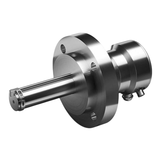
Page 16: Refractometer Structure
Chapter 2 – Product overview 2.5 Refractometer structure Figure 2 PR53 refractometer structure Main circuit board CCD Charge Coupled Device Disc springs CORE‑Module Light source Prism Prism gasket Integrated temperature sensor The measurement prism (6) is flush-mounted to the surface of the probe tip. The prism (6) and all the other optical components are fixed to the solid CORE‑Module (4), which is springloaded (3) against the prism gasket (8). -
Page 17: Storing And Transporting
PR53 Series User Guide M212898EN-C 2.6 Storing and transporting Soft shell packaging prevents damage to the components of the refractometer. Transport the device in its original packaging. Before storing, remove any dirt and grease from the refractometer and make sure that it is dry. -
Page 18: Refractometer Connections
3.6 mA. The output is configurable: The output value (refractive index, temperature, concentration, quality factor), scaling, and error status indication level can be configured using the Vaisala Insight software and a USB adapter. The connection header also has an RS-485 port. This allows using the refractometer directly as a Modbus RTU server device. -
Page 19: System Wiring
PR53 Series User Guide M212898EN-C Analog output (-) Analog output (+) VIN (+) VIN (-) SHIELD (Optional) Figure 4 Connecting wires inside the refractometer (analog output) More information ‣ Starting up refractometer with Indigo520 (page 26) 3.2 System wiring The analog and Modbus RTU wiring configurations are examples of system wiring. -
Page 20: Figure 5 Wiring Diagram For Pr53 And Indigo520
Chapter 3 – Refractometer connections Indigo520 wiring Indigo520 PR53 Relay 1 Relay 2 Analog outputs mA 1 mA 2 mA 3 mA 4 See manual for Indigo520 power options and specifications (M212287EN) 4 – 20 mA output 4 4 – 20 mA output 3 4 –... -
Page 21: Wiring Considerations
PR53 Series User Guide M212898EN-C Modbus RTU system Receiving system (Modbus RTU) PR53 Figure 7 Wiring diagram for PR53 and Modbus RTU 3.3 Wiring considerations The chassis ground and ground terminal are electrically connected. Grounding can be done either by connecting the cable shield to the respective terminal in the wiring header, or alternatively by connecting the cable shield to the cable gland. -
Page 22: Figure 8 Wiring Pr53 To Indigo520
Chapter 3 – Refractometer connections PR53 Indigo520 Terminal Terminal VIN + VIN + RS-485 - RS-485 - RS-485 - RS-485 - RS-485 + RS-485 + RS-485 + RS-485 + VIN - VIN - Signal Ground Signal Ground SHIELD Figure 8 Wiring PR53 to Indigo520... -
Page 23: User Interfaces
Indigo520 transmitter, Indigo80 handheld indicator or Insight software. • Red indicates a critical failure where user interference is required. When the red LED is on, the refractometer may need to be sent to Vaisala for service. Contact helpdesk@vaisala.com. The error codes can be read either through the Indigo520 transmitter, Modbus RTU port, Indigo80 handheld indicator, or Vaisala Insight software with a USB adapter. -
Page 24: Indigo520 User Interfaces
Chapter 4 – User interfaces 4.2 Indigo520 user interfaces Vaisala Indigo520 is a transmitter that accommodates maximum of two PR53 refractometers for liquid measurements. The transmitter can display measurements on the spot as well as transmit them to automation systems through analog signals, control relays, or Modbus TCP/IP protocol. -
Page 25: Vaisala Insight Pc Software
• See real-time measurement data. • Manage concentration curves • Calibrate and adjust the device. Download Insight at www.vaisala.com/insight. The refractometer can be connected to Insight using a Vaisala Indigo USB adapter (item code USB2). More information ‣ Connecting to Insight software (page 41) 4.4 Modbus RTU... - Page 26 Chapter 4 – User interfaces When PR53 is connected to Indigo520, Indigo provides more analog output channels. The integrated analog output channel and the Indigo520 analog outputs are independent from each other, and can also be used simultaneously. For configuring analog output with Indigo520, see Indigo500 User Guide (M212287EN).
-
Page 27: Start-Up
PR53 Series User Guide M212898EN-C 5. Start-up 5.1 Start-up The PR53 unit is configured at the factory and ready to be used. The concentration model has been set up according to the order. If the concentration model needs to be changed, it can be done using the service port and Insight software. - Page 28 Chapter 5 – Start-up 3. After the refractometer has been detected, configure the numerical and graphical display views and analog output channels using the Indigo520 display or the web user interface. Indigo500 User Guide (M212287EN) for details. If you have the optional prism wash system installed, you need to perform a prism wash test.
-
Page 29: Using Refractometer With Vaisala Indigo520
PR53 Series User Guide M212898EN-C 6. Using refractometer with Vaisala Indigo520 6.1 Vaisala Indigo520 transmitter With Vaisala Indigo520 Transmitter, you can: • View the refractometer status • Adjust concentration measurement • RI calibration • Configure analog output channel • Configure analog output signal damping •... -
Page 30: General Settings
Chapter 6 – Using refractometer with Vaisala Indigo520 4. Connect the wires inside the transmitter, see Indigo500 User Guide (M212287EN). 6.3 General settings You can edit the general settings of the refractometer in Menu > <your refractometer> > General. In General, you can give a custom name to the refractometer. -
Page 31: Concentration Curve
PR53 Series User Guide M212898EN-C Light area Pt-1000 Refractive index Concentration curve Temperature concentration Field adjustment Adjusted concentration Damping Concentration Analog output Figure 12 Concentration measurement layers Light area information comes from the CCD element and temperature information from Pt-1000 temperature element. The position of the shadow edge is light area and scaled 0–... -
Page 32: Table 5 C-Parameters
16 parameters, C-parameters. A concentration curve is specific to the given process medium, for example, sucrose or sodium hydroxide. The set of parameters is given by Vaisala. Do not alter the C-parameters, except if you are changing to another process medium. - Page 33 PR53 Series User Guide M212898EN-C Accurate calibration is only achieved if the sample is taken correctly. Pay special attention to following details: • Field adjustment using the process liquid must always be made inline. • The sampling valve and the refractometer should be installed close to each other in the process.
- Page 34 A concentration curve is specific to the given process medium, for example, sucrose or sodium hydroxide. The set of parameters is given by Vaisala. Do not alter the concentration curve parameters, except if you are changing to another process medium.
-
Page 35: Field Sample
Email the data to your local Vaisala representative. Vaisala makes a computer analysis of the data and sends optimal calibration parameters to be entered into the Indigo520 transmitter or Insight PC software. -
Page 36: Preparing Ri Calibration
Chapter 6 – Using refractometer with Vaisala Indigo520 The refractometer comes with a calibration certificate which ensures that it has fulfilled the measurement criteria when sent from the factory. RI calibration is needed when the optics of the device is serviced and RI adjustment needs to be performed. -
Page 37: Performing Ri Calibration With Indigo520
PR53 Series User Guide M212898EN-C 5. Let the refractometer and sample liquid temperature settle to room temperature, +20 … +30 ℃ (+68 … +86 ℉). Calibration must be done within this temperature range. The cooling of the refractometer may take several hours. -
Page 38: Configuring Analog Outputs With Indigo520
Chapter 6 – Using refractometer with Vaisala Indigo520 6. Once the calibration process is ready, results are displayed in the results screen. You can later view the results of a calibrated point by selecting a calibration point tile from the calibration view. -
Page 39: Linear Damping
PR53 Series User Guide M212898EN-C In the exponential damping, the damping time is the time it takes for the concentration measurement to reach half of its final value at a step change. For example, if the concentration changes from 50 % to 60 % and damping time is 10 s, it takes 10 s for the Indigo520 to display concentration 55 %. -
Page 40: Slew Rate Limit
Chapter 6 – Using refractometer with Vaisala Indigo520 The following figure shows how linear damping time affects the measurement. Figure 14 Linear damping 6.8.3 Slew rate limit If the process signal has short erroneous high or low peaks, the slew rate limiting can be used to cut their effects. -
Page 41: Figure 15 Slew Rate Damping
PR53 Series User Guide M212898EN-C The following figure gives an example of different slew rate limits. Figure 15 Slew rate damping To avoid overdamping, do not make the signal insensitive. -
Page 42: Using Refractometer With Vaisala Insight Software
Chapter 7 – Using refractometer with Vaisala Insight software 7. Using refractometer with Vaisala Insight software 7.1 Insight PC software With Vaisala Insight PC software, you can: • Configure analog output channel • Configure signal damping • Adjust concentration curves • Calibrate the RI measurement •... -
Page 43: Figure 16 Connecting Refractometer To Insight
PR53 Series User Guide M212898EN-C Figure 16 Connecting refractometer to Insight 1. Open the Insight software on your PC. 2. Connect the USB cable to a free USB port on the PC. -
Page 44: Insight Main View
Chapter 7 – Using refractometer with Vaisala Insight software 7.3 Insight main view Select to access the device-specific menu. • Configure device: environmental compensation settings, analog output 1 and 2 settings, filtering factor and general settings. • Export settings: creates a text file export of the device settings. -
Page 45: Basic And Advanced User Modes
Depending on the connected device, switching to Advanced mode may provide access to additional configuration options. Use these options only as described in the product documentation or as instructed by Vaisala support. 7.4 Concentration measurement Adjustment of the raw concentration value may be required to compensate for some process conditions or to fit the measurement to the laboratory results. -
Page 46: Concentration Curve
Chapter 7 – Using refractometer with Vaisala Insight software Light area Pt-1000 Refractive index Concentration curve Temperature concentration Field adjustment Adjusted concentration Damping Concentration Analog output Figure 17 Concentration measurement layers Light area information comes from the CCD element and temperature information from Pt-1000 temperature element. -
Page 47: Table 6 C-Parameters
16 parameters, C-parameters. A concentration curve is specific to the given process medium, for example, sucrose or sodium hydroxide. The set of parameters is given by Vaisala. Do not alter the C-parameters, except if you are changing to another process medium. - Page 48 Chapter 7 – Using refractometer with Vaisala Insight software Accurate adjustment is achieved only if the sample is taken correctly. Pay special attention to following details: • Field adjustment using the process liquid must always be made inline. • The sampling valve and the refractometer should be installed close to each other in the process.
- Page 49 A concentration curve is specific to the given process medium, for example, sucrose or sodium hydroxide. The set of parameters is given by Vaisala. Do not alter the concentration curve parameters, except if you are changing to another process medium.
- Page 50 Chapter 7 – Using refractometer with Vaisala Insight software 2. You can change the C parameters in > Configure device > Concentration curve 1/2/3/4. Changing from one concentration curve to another changes the way concentration is calculated from monitored liquids. The refractometer will restart to apply the change.
-
Page 51: Field Sample
Email the data to your local Vaisala representative. Vaisala makes a computer analysis of the data and sends optimal calibration parameters to be entered into the Indigo520 transmitter or Insight PC software. -
Page 52: Preparing Ri Calibration
Chapter 7 – Using refractometer with Vaisala Insight software • Environment with a good ventilation Nominal reference RI liquids There are two prism types, each of which have their own nominal reference RI liquid sets. You can check which prism your refractometer has from the configuration code by the side of the refractometer. -
Page 53: Completing Ri Calibration
PR53 Series User Guide M212898EN-C 5. Apply sample liquid onto the sample holder and place the light cover on top. Do not hold the refractometer or sample liquid container in your hand or near external heat sources during calibration. Changes in the refractometer or sample liquid temperature may decrease the quality of the measurement point or cause it to fail. -
Page 54: Ri Adjustment
In order to perform RI calculation adjustment, you need to calibrate at least five calibration points that all have a different Nominal RI. You can do this in the RI calibration menu. Vaisala recommends that you perform RI adjustment based on a recent calibration. -
Page 55: Adjusting Temperature Using Previously Measured Value
PR53 Series User Guide M212898EN-C 3. Wait for the measurement to stabilize fully. The graph shows readings of the last 60 minutes. 4. When the measurement has stabilized, select the Reference value, point 1 text box and enter the temperature of calibration point 1. Select ENTER or click outside the field when done. -
Page 56: Creating Blank Image
Chapter 7 – Using refractometer with Vaisala Insight software • Not applicable: Appears only if VD algorithm is used as detection algorithm. More information ‣ Creating blank image (page 55) 7.8.1 Creating blank image This is a maintenance operation only. The procedure should only be done if the prism has been replaced, for example. -
Page 57: Adjusting Output Level For Analog Output 1
PR53 Series User Guide M212898EN-C • No sample error output and No sample error output level allow you to set a secondary mA output value for empty pipe (message No liquid detected) to differentiate it from the other messages that cause the measurement to revert to default mA. By default the secondary mA output is disabled. -
Page 58: Configuring Analog Output Signal Damping
Chapter 7 – Using refractometer with Vaisala Insight software 10. Disable the Test mode (switch to OFF position) and select Close to exit the calibration mode. 11. Replace the original analog output wiring. 7.9.2 Configuring analog output signal damping You can apply signal damping in >... -
Page 59: Figure 18 Exponential Damping
PR53 Series User Guide M212898EN-C The following figure shows how exponential damping time affects the measurement. Figure 18 Exponential damping 7.9.2.2 Linear damping If the process has fast step changes, linear (fast) damping gives shorter settling time. In the linear damping, the output is the running average of the signal during the damping time. -
Page 60: Figure 19 Linear Damping
Chapter 7 – Using refractometer with Vaisala Insight software The following figure shows how linear damping time affects the measurement. Figure 19 Linear damping 7.9.2.3 Slew rate limit If the process signal has short erroneous high or low peaks, the slew rate limiting can be used to cut their effects. -
Page 61: Configuring Modbus Communication Settings With Insight
PR53 Series User Guide M212898EN-C The following figure gives an example of different slew rate limits. Figure 20 Slew rate damping To avoid overdamping, do not make the signal insensitive. 7.10 Configuring Modbus communication settings with Insight You can configure the following Modbus communication settings with the Insight PC software: •... -
Page 62: Restoring Factory Settings
Chapter 7 – Using refractometer with Vaisala Insight software 3. Select Save to store the settings. More information ‣ Modbus RTU (page 24) ‣ Modbus registers (page 88) ‣ System wiring (page 18) ‣ Starting up stand-alone refractometer (page 26) 7.11 Restoring factory settings... -
Page 63: Preventive Maintenance
PR53 Series User Guide M212898EN-C 8. Preventive maintenance 8.1 Preventive maintenance PR53 process refractometers do not have wearing parts or periodically changeable parts. Depending on the process conditions, PR53 process refractometers may never need to be serviced. There a few things that should be monitored: Table 7 Preventive maintenance... - Page 64 Chapter 8 – Preventive maintenance Cleaning the refractometer Clean the refractometer by using a suitable solvent and a moist cloth.
-
Page 65: Troubleshooting
PR53 Series User Guide M212898EN-C 9. Troubleshooting 9.1 Troubleshooting messages Table 8 Hardware troubleshooting Problem Severity Cause Corrective action level Message Internal Error The relative humidity Make sure that the prism humidity too high measured at the seal is intact and the cover refractometer's processor is closed. -
Page 66: Table 9 Measurement Troubleshooting
Chapter 9 – Troubleshooting Problem Severity Cause Corrective action level Analog output signal is not Check wiring, see the model-specific installation guide. working as expected If the analog output signal does not correspond to the concentration display, check output signal configuration, see Diagnostics. - Page 67 PR53 Series User Guide M212898EN-C Problem Severity Cause Corrective action level Message Blank image Critical Blank image is missing or A trained person can corrupted corrupted. create a blank image. Contact helpdesk@vaisala.com. Message External light Error The measurement is not...
- Page 68 Contact your used curve, the sales representative or measurement result may helpdesk@vaisala.com. be unreliable. 2. If you know that the measurement does not correspond to the true concentration value, the refractometer needs to be serviced.
-
Page 69: Diagnostic Message Priorities
PR53 Series User Guide M212898EN-C Problem Severity Cause Corrective action level Message Calibration Warning When calibration mode is Make sure that the mode active active, the refractometer calibration mode is off in will not calculate the all used user interfaces. -
Page 70: Measurement Status Details
Invalid calculation parameters: RI adjustment parameters are invalid. Perform RI adjustment or contact helpdesk@vaisala.com. Blank image corrupted: Blank image for IDS image detection algorithm is corrupted. Create blank image or contact helpdesk@vaisala.com. 9.3 Measurement status details There are different measurement statuses that you can view in the Diagnostics tab of the Insight software. -
Page 71: Calibration Check
PR53 Series User Guide M212898EN-C Message C measurement status T measurement status Field sample status Over range (O) Refractometer is Refractometer is measuring a value measuring a value outside concentration outside concentration curve measurement curve measurement range. range. Locked (L) - Page 72 Chapter 9 – Troubleshooting • Reference liquid related failures: • There is coating on the prism. Clean the prism and the sample holder, and then recalibrate. • There are impurities in the sample liquid. Clean the prism and the sample holder. Replace the sample liquid and then recalibrate.
-
Page 73: Technical Data
PR53 Series User Guide M212898EN-C 10. Technical data 10.1 Compatibility PR53 refractometer is mechanically compatible with most PR-23 and PR-43 refractometers. The communication and electronic system has to be updated with the refractometer change. 10.2 PR53 common specifications Table 12 Measurement performance Property Description/Value... -
Page 74: Table 14 Compliance
External connectors 1 × M12 F 4 pins, A-coded 2 × M16×1.5 cable gland, Cable D 5–10 mm / Adapter for conduit entry M16×1.5 / NPT ½" For USB2 adapter and Insight software, see www.vaisala.com/insight. Table 14 Compliance Property Specification Electromagnetic compatibility (EMC) EN 61326‑1, industrial environment... -
Page 75: Pr53Ac Specifications
PR53 Series User Guide M212898EN-C Property Specification Pressure CRN all territories, ASME BPVC Sec VIII Div. 1 Ed. 2021 Material compliance FDA 21 CFR 177.150, 177.2600, 177.1550 EC 1935/2004 EC 2023/2006, GMP EU 10/2011 Compliance marks CE, China RoHS, RCM, UKCA... -
Page 76: Figure 21 Pr53Ac Process Temperature, Options Sanitary 2.5" And Type N (Indicative)
Chapter 10 – Technical data Process temperature (°C) - 40 - 20 140 150 - 20 Normal operation Not recommended for continuous operation Out of operating range, do not install Figure 21 PR53AC process temperature, options Sanitary 2.5" and Type N (indicative) Process temperature (°C) - 25 Sanitary high pressure clamp 2.5"... -
Page 77: Table 17 Mechanical Specifications
Dummy plug EN 1.4305 (AISI 303) AGRO 8717.96.08.70 Conduit hub EN 1.4404 (AISI 316L) Vaisala, DRW257718, M16×1.5 / NPT ½ in M12 connector Gland, EN 1.4305 (AISI 303) Contacts, CuZn with Ni/Au plating Phoenix Contact, 1405233, M12/4(M), A, 4×0.34 mm , TPE, 0.5 m... -
Page 78: Pr53Ap Specifications
Chapter 10 – Technical data 3-A certificate, EHEDG certificate. 10.4 PR53AP specifications Table 18 Operating environment Property Specification Process parameters Process temperature –40 … +150 °C (–40 … +302 °F) Design temperature +180 °C (356 °F) Design pressure 40 bar Operating environment Storage temperature −40 …... -
Page 79: Figure 23 Pr53Ap Process Temperature (Indicative)
PR53 Series User Guide M212898EN-C Process temperature (°C) - 40 - 20 140 150 - 20 Normal operation Out of operating range, do not install Figure 23 PR53AP process temperature (indicative) Process temperature (°C) - 25 Sanitary high pressure clamp 2.5"... -
Page 80: Table 20 Mechanical Specifications
Dummy plug EN 1.4305 (AISI 303) AGRO 8717.96.08.70 Conduit hub EN 1.4404 (AISI 316L) Vaisala, DRW257718, M16×1.5 / NPT ½ in M12 connector Gland, EN 1.4305 (AISI 303) Contacts, CuZn with Ni/Au plating Phoenix Contact, 1405233, M12/4(M), A, 4×0.34 mm , TPE, 0.5 m... -
Page 81: Pr53Gc Specifications
PR53 Series User Guide M212898EN-C Property Specification Weight 3.6–4.2 kg (7.94–9.26 lb) Material certificate included. Manufacturer's declaration included. ADI free, FDA 21 C.F.R 177.1550, 3A Sanitary Standard, USP Class VI <88>, 70 °C. 3-A certificate, EHEDG certificate. 10.5 PR53GC specifications Table 21 Operating environment... -
Page 82: Figure 25 Pr53Gc Process Temperature (Indicative)
Chapter 10 – Technical data Process temperature (°C) - 40 - 20 140 150 - 20 Normal operation Not recommended for continuous operation Out of operating range, do not install Figure 25 PR53GC process temperature (indicative) Process temperature (°C) - 25 L coupling Figure 26 PR53GC process pressure Table 22 Mechanical specifications... -
Page 83: Pr53Gp Specifications
Dummy plug EN 1.4305 (AISI 303) AGRO 8717.96.08.70 Conduit hub EN 1.4404 (AISI 316L) Vaisala, DRW257718, M16×1.5 / NPT ½ in M12 connector Gland, EN 1.4305 (AISI 303) Contacts, CuZn with Ni/Au plating Phoenix Contact, 1405233, M12/4(M), A, 4×0.34 mm , TPE, 0.5 m... -
Page 84: Figure 27 Pr53Gp Process Temperature (Indicative)
Chapter 10 – Technical data Property Specification Process temperature –40 … +150 °C (–40 … +302 °F) Design temperature +180 °C (356 °F) Design pressure 40 bar -40 ... +130 °C EPDM gasket, -40... +150 °C EHEDG gasket. Maximum momentary temperature peak. Maximum at +20 °C, operating pressure to the clamp rating pressure. -
Page 85: Table 24 Mechanical Specifications
Dummy plug EN 1.4305 (AISI 303) AGRO 8717.96.08.70 Conduit hub EN 1.4404 (AISI 316L) Vaisala, DRW257718, M16×1.5 / NPT ½ in M12 connector Gland, EN 1.4305 (AISI 303) Contacts, CuZn with Ni/Au plating Phoenix Contact, 1405233, M12/4(M), A, 4×0.34 mm , TPE, 0.5 m... -
Page 86: Spare Parts And Accessories
10.8 Recycling instructions These recycling instructions guide you on the end-of-life treatment of this Vaisala product. As waste regulations and infrastructure vary in each country, these instructions only indicate the different components to be separated and common ways to handle them. Always follow local requirements when disposing of the product. -
Page 87: Figure 29 Materials For Recycling
PR53 Series User Guide M212898EN-C Electrical and electronical waste Metal waste Other Figure 29 Materials for recycling Table 26 Materials for recycling Part Material Recycling Cover Stainless Steel Metal waste... - Page 88 Chapter 10 – Technical data Part Material Recycling Screws and washers Stainless steel Metal waste O-rings Other Electronics Various Electrical and electronic waste Enclosure Stainless Steel Metal waste Prism Sapphire Other cables Various Electrical and electronic waste Cable gland Various Metal waste Conduit hub Various...
-
Page 89: Modbus Registers
PR53 Series User Guide M212898EN-C 11. Modbus registers 11.1 Modbus registers Table 27 Measurement data registers (read-only) Register number Address Register Data format Unit (decimal) (hexadecimal) description 0002 Concentration 32-bit float 0003 0004 Temperature 32-bit float °C 0005 0006 32-bit float concentration 0007... -
Page 90: Table 29 Status Registers (Read-Only)
Error code 32-bit integer 0203 0204 Error subcode 32-bit integer 0205 Error subcode is meant to be sent to Vaisala service along with error code. Table 30 Error code encoding … 17 16 15 14 13 12 11 10 … System Environment... -
Page 91: Table 31 Device Information Registers (Read-Only)
PR53 Series User Guide M212898EN-C Error code register value Corresponding error Image detection status Image quality low. External light level high. Prism coating detected. No liquid detected. No optical image. External light level too high. Temperature measurement status Temperature measurement error. -
Page 92: Table 32 Configuration Registers
Chapter 11 – Modbus registers Register number Address Register Data format Example output (decimal) (hexadecimal) description 7433 1D08 – ProductCode text “PR53” 1D0F 7441 1D10 –1D17 SerialNumber text “J1140501” 7449 1D18 – FirmwareVersion text “1.0.0” 1D1F Table 32 Configuration registers Register number Address Register Data format... - Page 93 PR53 Series User Guide M212898EN-C Register number Address Register Data format Unit / Valid range (decimal) (hexadecimal) description 1538 0601 Bit rate (b/s) 16-bit integer 0 = 300 1 = 600 2 = 1200 3 = 2400 4 = 4800...
-
Page 94: Table 33 Concentration Curve Configuration Registers
Chapter 11 – Modbus registers Register number Address Register Data format Unit / Valid range (decimal) (hexadecimal) description 1801 0708 No sample error 32-bit float 0.0–20.5 mA output level 0709 Temperature offset 8967 2306 T offset 32-bit float °C * Depends on the active concentration curve Table 33 Concentration curve configuration registers Register Address... - Page 95 PR53 Series User Guide M212898EN-C Register Address Register Data format Unit Writable number (hexadecimal) description (decimal) 14 + base 000E – Description text 002D base 95 + base 005F Chemical 32-bit float coefficients, base 0060 base 97 + base 0061...
- Page 96 Chapter 11 – Modbus registers Register Address Register Data format Unit Writable number (hexadecimal) description (decimal) 111 + base 006F Chemical 32-bit float coefficients, base 0070 base 113 + base 0071 + base Chemical 32-bit float coefficients, 0072 + base 115 + base 0073 + base Chemical...
-
Page 97: Table 34 Test Value Registers
PR53 Series User Guide M212898EN-C Register Address Register Data format Unit Writable number (hexadecimal) description (decimal) 131 + base 00A1 + base Field gain 32-bit float 00A2 base Concentration curve bases 3073 0C00 Concentration curve 1 3329 0D00 Concentration curve 2... - Page 98 Calibration date in YYYY-MM-DD format. Empty string if not set/ valid. 82hex ”Vaisala/HEL” CalibrationText Calibration information text. Empty string if not set/valid. Vaisala-specific device information object More information ‣ Modbus RTU (page 24) ‣ Configuring Modbus communication settings with Insight (page 60)
-
Page 99: Appendix A: Principle Of Measurement
M212898EN-C Appendix A. Principle of measurement The Vaisala K‑PATENTSâ inline process refractometer determines the refractive index (RI) of the process solution. It measures the critical angle of refraction using a yellow LED light source with the same wavelength (589 nm) as the sodium D line. Light from the light source (L) in the following figure is directed to the interface between the prism (P) and the process medium (S). -
Page 100: Figure 31 Optical Images
Appendix A – Principle of measurement The refractive index changes with the process solution concentration and temperature. For most solutions the refractive index increases when the concentration increases. At higher temperatures the refractive index is smaller than at lower temperatures. From this follows that the optical image changes with the process solution concentration as shown in the following figure. -
Page 101: Appendix B: Analyzing Optical Image
PR53 Series User Guide M212898EN-C Appendix B. Analyzing optical image The optical image can tell you about problems, for example, with the condition of the prism. Y-axis is light intensity and X-axis the position of the shadow edge. RI calibration follows the X- axis. -
Page 102: Table 37 Prism Scaling
Appendix B – Analyzing optical image Prism coated CCD card is disconnected or faulty, or LED card is disconnected or faulty, or the optical fiber is broken Table 37 Prism scaling Good • Measurement status Normal operation. • Observe the angle, drop from high intensity light to low light intensity should be as steep as possible. - Page 103 PR53 Series User Guide M212898EN-C...
-
Page 104: Maintenance And Calibration Services
Maintenance and calibration services Vaisala offers comprehensive customer care throughout the life cycle of our measurement instruments and systems. Our factory services are provided worldwide with fast deliveries. For more information, see www.vaisala.com/ calibration. • Vaisala Online Store at store.vaisala.com is available for most countries. - Page 107 www. v aisala.com...
Need help?
Do you have a question about the PR53 Series and is the answer not in the manual?
Questions and answers