
Related Manuals for Vaisala Polaris PR53AC


Summary of Contents for Vaisala Polaris PR53AC
- Page 1 M212866EN-B Installation Guide Vaisala Polaris Process Refractometer PR53AC...
- Page 2 This product contains software developed disclosed to a third party without prior by Vaisala or third parties. Use of the written permission of the copyright holder. software is governed by license terms and Translated documents and translated...
- Page 3 Table of contents English.............................5 Deutsch............................33 Français............................61 Español............................91 Italiano............................119 日本語......................147 中文........................ 175...
- Page 4 M212866EN-B...
-
Page 5: Table Of Contents
Table of contents About this document..................6 Version information........................6 Related manuals...........................6 Documentation conventions....................6 Trademarks............................ 7 Planning the installation...................8 PR53 product overview......................8 Installation safety.........................8 Required personnel........................9 Package contents........................10 Needed tools..........................10 Choosing the installation location..................10 Installation environment....................11 Installation dimensions for hygienic processes............12 Package recycling........................12 Mechanical installation..................13 Installing the refractometer.....................13... -
Page 6: About This Document
About this document Version information This document provides instructions for installing Vaisala Polaris PR53AC sanitary compact process refractometer. Table 1 Document versions (English) Document code Date Description M212866EN‑A April 2023 First release. M212866EN‑B June 2023 Language versions added to the manual. -
Page 7: Trademarks
Lists tools needed to perform the task. Indicates that you need to take some notes during the task. Trademarks Vaisalaâ is a registered trademark of Vaisala Oyj. Indigo ™ is a trademark of Vaisala Oyj. Varinlineâ is a registered trademark of GEA Tuchenhagen GMBH. -
Page 8: Planning The Installation
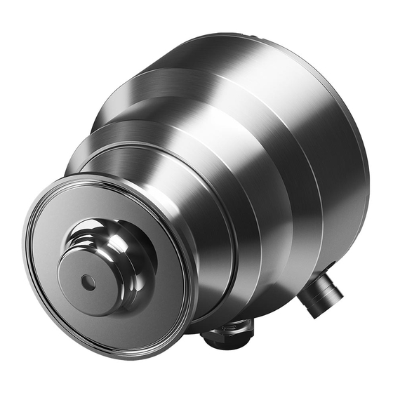
The measurement is based on the refraction of light in the process medium, an accurate and safe way of measuring liquid concentration. Figure 1 Refractometer equipment Vaisala Polaris ™ Process Refractometers Interconnecting cables Vaisala Indigo520 transmitter (optional) The inline process refractometer (1) measures the refractive index RI and the temperature of the process medium. -
Page 9: Required Personnel
WARNING! If you have a wash system in place or are planning to install a wash system, make sure to familiarize yourself with safety regulations related to hot steam and water. For more details, see related wash system user guide. WARNING! Follow local and state legislation and regulations on occupational safety. -
Page 10: Package Contents
Package contents Refractometer Cable gland and conduit hub Cable (ordered separately) Mounting kit with either standard or high‑pressure clamp (optional) Flow cell (optional) Cooling cover (optional) Needed tools • TX20 Torx key • 9/16 in wrench (for high pressure clamps) •... -
Page 11: Installation Environment
• If the process pipe diameter varies, select the position with the smallest diameter (and highest velocity). This keeps the prism cleaner. Table 3 Recommended mounting locations Location Details Image Outer pipe bend • There is sufficient process flow to the prism that keeps the prism clean. -
Page 12: Installation Dimensions For Hygienic Processes
When installing the refractometer in a hygienic process, make sure the length of the dead leg (L) is smaller than its inner diameter (D). With probe model refractometers, follow the equation L≤(D-d). Sensor Dead space Process area Package recycling Save the original packaging for safely transporting the device to Vaisala for servicing. M212866EN-B... -
Page 13: Mechanical Installation
• Gasket • Clamp These are general instructions for the refractometer mounting. Plan the process‑specific installation according to your requirements. Contact Vaisala helpdesk for further assistance if needed. If you are using a flow cell, see Installing refractometer with flow cell (page 15). - Page 14 3. Weld the ferrule into the process pipeline. For the optimal self-cleaning properties, install the refractometer in a 10 ° downwards angle. 10° mm [in] If your system must comply with EHEDG, 3-A or other sanitary standard, see the standard for more detailed welding instructions. 4.
-
Page 15: Installing Refractometer With Flow Cell
5. Mount the refractometer. Make sure the cable glands on the refractometer are in a downward position. a. Finger tighten to 3 Nm if you are using the standard clamp (with one tightening screw). b. Tighten to 28 Nm with a 9/16 inch wrench if you are using the high pressure clamp (with two tightening screws). - Page 16 Follow these instructions to install the refractometer with a flow cell. Notice that the images in this instruction may differ from the flow cell you have for your process. 1. Make sure the process line is depressurized. 2. Weld ferrules into the process pipeline according to material and system requirements. Table 5 Flow cell installation dimension Flow cells 1"...
- Page 17 4. Install flow cell using clamps. a. Finger tighten to 3 Nm if you are using the clamp with one tightening screw. b. Tighten to 28 Nm with 9/16" wrench if you are using the sanitary clamp with two tightening screws.
- Page 18 5. Install gasket for the refractometer. 6. Mount the refractometer. Make sure the cable glands on the refractometer are in a downward position. a. Finger tighten to 3 Nm if you are using the standard clamp (with one tightening screw). b.
-
Page 19: Electrical Installation
Electrical installation Connecting the refractometer wiring • Cable gland or conduit hub • Cables • TX20 Torx key • 22‑mm wrench • 24‑mm wrench WARNING! Make sure that electrical connections adhere to local and state legislation and regulations. WARNING! Make sure that you prepare and connect only de-energized wires. 1. - Page 20 3. Remove the dust plug from the refractometer. M212866EN-B...
- Page 21 4. Install the cable gland or conduit hub adapter. a. Tighten the upper part of the cable gland to 5 Nm using a 22‑mm wrench. b. Tighten the conduit hub adapter to 5 Nm using 24‑mm wrench.
- Page 22 5. Install the cable with the cable gland or conduit hub. a. Feed the cable through the cable gland. Ground the cable gland by removing the 15‑mm sleeve from the cable, brushing the metal braid upwards and folding it over. Make sure the wires reach the terminal.
- Page 23 CAUTION! If the conduit is metal, it grounds the cable at the refractometer side. If the conduit is not metal, use the SHIELD connection at the terminal block (shown in the figure). For the power side grounding, follow local regulations. 6.
- Page 24 7. Reinstall the refractometer cover. Tighten screws to 2 Nm using a TX20 Torx key. Be careful not to overtighten. The screws may break. If you are connecting to Indigo520 transmitter, see Indigo500 User Guide (M212287EN) for wiring options. M212866EN-B...
-
Page 25: Finalizing Installation
Finalizing installation • Check that the pipe connections are tightened properly. • Check that there are no leaks in the process. • Check that the piping is firmly in place and there is no excessive vibration. PR53 Series User Guide (M212898EN) for further instructions on startup and calibration. -
Page 26: Technical Data
Technical data Compatibility PR53 refractometer is mechanically compatible with most PR-23 and PR-43 refractometers. The communication and electronic system has to be updated with the refractometer change. Refractometer specifications Mechanical specifications Table 6 Mechanical specifications Property Specification Wetted parts Sensor head EN 1.4435 BN2 (AISI 316L) Surface roughness Ra 0.8 μm... - Page 27 Property Specification Weight 2.7 kg (5.95 lb) EN 10204 / 3.1 certificate included. Manufacturer's declaration included. ADI free, FDA 21 C.F.R 177.1550, 3A Sanitary Standard, USP Class VI <88>, 70 °C. 3-A certificate, EHEDG certificate. Electrical specifications Table 7 Inputs and outputs Property Specification Supply...
-
Page 28: Spare Parts And Accessories
1 × M12 F 4 pins, A-coded 2 × M16×1.5 cable gland, Cable D 5 ... 10 mm / Adapter for conduit entry M16×1.5 / NPT ½" For USB2 adapter and Insight software. See www.vaisala.com/insight. Environmental specifications Table 8 Operating environment... - Page 29 Item Sanitary clamp 2.5” High-pressure clamp 2.5" Blind flange 2.5” Sanitary gasket, 2.5", EPDM Sanitary gasket, 2.5”, EHEDG compliant, PTFE/steel, Combifit VOE-2034 (optional) Table 10 Mounting accessories for PR53AC Type N Item Type N clamp 2.5”, DN 50/40 Type N blind flange Gasket 59.5×3 mm, EPDM Flow cells Table 11 SEFC Sanitary Elbow Flow Cell...
- Page 30 Table 12 SEFCL Sanitary Elbow Flow Cell, for Large Pipelines Item Configuration code SEFCL Sanitary Elbow Flow Cell, for Large Pipelines Wetted parts Sanitary coupling 3” Sanitary coupling 4” Wash nozzle No wash nozzle option Steam wash nozzle Water wash nozzle Pressurized water wash nozzle Documentation Material certificate included...
-
Page 31: Sanitary Specifications
Sanitary specifications Table 15 Sanitary compliance Property Specification Hygienic design 3‑A 46-04 EHEDG Compliance marks 3‑A, EHEDG Biocompatibility USP Class VI <88>, 70 °C ADI free (Animal Derived Ingredients) For EHEDG compliant installation, use 2.5" / 4" sanitary gasket. Interconnecting cable specifications Table 16 Interconnecting cable specifications Property Specification... -
Page 32: Warranty
Please see the applicable supply contract or Conditions of Sale for details of the warranty for each product. Technical support Contact Vaisala technical support at helpdesk@vaisala.com. Provide at least the following supporting information as applicable: • Product name, model, and serial number •... - Page 33 Inhaltsverzeichnis Über dieses Dokument...................34 Versionsinformation......................... 34 Verwandte Handbücher......................34 Konventionen in der Dokumentation...................34 Marken............................35 Planen der Installation................... 36 PR53 Produktübersicht......................36 Sicherheit bei der Installation....................36 Erforderliches Personal......................37 Inhalt der Packung........................38 Benötigte Werkzeuge......................38 Auswahl der Installationsposition..................38 Installationsumgebung....................40 Einbaumaße für hygienische Prozesse............... 40 Verpackungsrecycling......................
-
Page 34: Über Dieses Dokument
Dokumentnum- Name M212898EN Vaisala Polaris Process Refractometer PR53 Series User Guide M212808EN Vaisala Polaris Process Refractometer PR53 Prism Wash System User Guide M212290EN Vaisala Indigo500 Series Transmitters Quick Guide M212287EN Vaisala Indigo500 Series Transmitters User Guide Konventionen in der Dokumentation WARNUNG! Eine Warnung weist auf eine ernste Gefahr hin. -
Page 35: Marken
Listet die zum Durchführen einer Aufgabe erforderlichen Tools auf. Weist darauf hin, dass Sie sich während der Aufgabe Notizen machen müssen. Marken Vaisalaâ ist eine eingetragene Marke von Vaisala Oyj. Indigo ™ ist eine Marke von Vaisala Oyj. Varinlineâ ist eine eingetragene Marke der GEA Tuchenhagen GmbH. -
Page 36: Planen Der Installation
Prozessleitung. Die Messung basiert auf der Lichtbrechung im Prozessmedium – eine genaue und sichere Methode zur Messung von Konzentrationen in Flüssigkeiten. Abbildung 2 Refraktometerausrüstung Vaisala Polaris ™ Prozessrefraktometer Verbindungskabel Messwertgeber Vaisala Indigo520 (optional) Der Inline-Refraktometersensor (1) misst den Brechungsindex RI und die Temperatur des Prozessmediums. -
Page 37: Erforderliches Personal
WARNUNG! Wenn Sie über ein Reinigungssystem verfügen oder die Installation eines Reinigungssystems planen, müssen Sie mit den Sicherheitsbestimmungen in Bezug auf heißen Dampf und heißes Wasser vertraut machen. Weitere Einzelheiten finden Sie im Benutzerhandbuch zum Reinigungssystem. WARNUNG! Halten Sie sich an die vor Ort und landesweit geltenden Gesetze und Vorschriften zum Arbeitsschutz. -
Page 38: Inhalt Der Packung
Inhalt der Packung Refraktometer Kabelverschraubung und Kabelkanalverschraubung Kabel (gesondert bestellen) Montagesatz mit Standard- oder Hochdruckklammer (optional) Durchflusszelle (optional) Kühlabdeckung (optional) Benötigte Werkzeuge • Torx-Schlüssel TX20 • 9/16"-Schraubenschlüssel (für Hochdruckschellen) • Schraubenschlüssel, 22 mm • Schraubenschlüssel, 24 mm • Schlitzschraubendreher Auswahl der Installationsposition Befolgen Sie diese Anweisungen zur Auswahl der richtigen Installationsposition für das Prozessrefraktometer. - Page 39 • Wenn die Temperatur im Verlauf des Prozessrohrs variiert, wählen Sie die Position mit der höchsten Prozesstemperatur. Dies minimiert das Risiko der Bildung geschichteter Ablagerungen auf dem Prisma, weil mit höherer Temperatur eine bessere Löslichkeit und eine niedrigere Viskosität einhergeht. •...
-
Page 40: Installationsumgebung
Länge der Totleitung (L) kleiner als sein Innendurchmesser (D) ist. Für Sonden-Refraktometer gilt die Gleichung L ≤ (D – d). Sensor Totraum Prozessbereich Verpackungsrecycling Bewahren Sie die Originalverpackung auf, um das Gerät zu Wartungszwecken sicher an Vaisala schicken zu können. M212866EN-B... -
Page 41: Mechanische Installation
• Dichtung • Klammer Diese allgemeinen Anleitungen gelten für die Montage des Refraktometers. Planen Sie die prozessspezifische Installation Ihren Anforderungen entsprechend. Kontaktieren Sie bei Bedarf den Vaisala Helpdesk. Wenn Sie eine Durchflusszelle verwenden, siehe Installation des Refraktometers mit Durchflusszelle (Seite 43). - Page 42 3. Schweißen Sie die Hülse in die Prozessleitung. Für optimale Selbstreinigung muss das Refraktometer in einem Abwärtswinkel von 10° montiert werden. 10° mm [in] Wenn das System EHEDG, 3-A oder anderen Hygienenormen entsprechen muss, beachten Sie die detaillierten Anweisungen zum Schweißen in der betreffenden Norm.
-
Page 43: Installation Des Refraktometers Mit Durchflusszelle
5. Montieren Sie das Refraktometer. Achten Sie darauf, dass die Kabelverschraubungen am Refraktometer nach unten weisen. a. Wenn Sie die Standardschelle (mit einer Befestigungsschraube) verwenden, ziehen Sie diese von Hand auf 3 Nm an. b. Ziehen Sie mit einem 9/16"-Schraubenschlüssel auf 28 Nm an, wenn Sie die Hochdruckschelle (mit zwei Befestigungsschrauben) verwenden. - Page 44 Befolgen Sie diese Anleitung, um das Refraktometer mit einer Durchflusszelle zu installieren. Beachten Sie, dass die Abbildungen in dieser Anleitung von der Durchflusszelle für Ihren Prozess abweichen können. 1. Stellen Sie sicher, dass die Prozessleitung drucklos ist. 2. Schweißen Sie je nach Material- und Systemanforderungen Hülsen in die Prozessleitung. Tabelle 21 Maße für die Montage der Durchflusszelle Durchfluss- 1"...
- Page 45 4. Montieren Sie die Durchflusszelle mit Klammern a. Wenn Sie die Schelle mit einer Befestigungsschraube verwenden, ziehen Sie diese von Hand auf 3 Nm an. b. Ziehen Sie mit dem 9/16"-Schraubenschlüssel auf 28 Nm an, wenn Sie die Sanitary- Klammer mit zwei Befestigungsschrauben verwenden.
- Page 46 5. Bauen Sie die Dichtung für das Refraktometer ein. 6. Montieren Sie das Refraktometer. Achten Sie darauf, dass die Kabelverschraubungen am Refraktometer nach unten weisen. a. Wenn Sie die Standardklammer (mit einer Befestigungsschraube) verwenden, ziehen Sie diese von Hand auf 3 Nm an. b.
-
Page 47: Elektrischer Anschluss
Elektrischer Anschluss Anschließen der Refraktometerkabel • Kabelverschraubung oder Kabelkanalverschraubung • Kabel • Torx-Schlüssel TX20 • Schraubenschlüssel, 22 mm • Schraubenschlüssel, 24 mm WARNUNG! Alle elektrischen Verbindungen müssen den örtlichen und staatlichen Gesetzen und Vorschriften entsprechen. WARNUNG! Sie dürfen nur Kabel vorbereiten und anschließen, an denen keine Spannung anliegt. - Page 48 3. Entfernen Sie den Staubstopfen vom Refraktometer. M212866EN-B...
- Page 49 4. Installieren Sie die Kabelverschraubung oder den Adapter des Rohrverschraubungsanschlusses. a. Ziehen Sie den oberen Teil der Kabelverschraubung mit einem 22-mm- Schraubenschlüssel auf 5 Nm an. b. Ziehen Sie den Adapter des Rohrverschraubungsanschlusses mit einem 24-mm- Schraubenschlüssel auf 5 Nm an.
- Page 50 5. Installieren Sie das Kabel mit der Kabelverschraubung oder der Kabelkanalverschraubung. a. Führen Sie das Kabel durch die Kabelverschraubung. Erden Sie die Kabelverschraubung, indem Sie die 15-mm-Hülse vom Kabel entfernen, das Metallgeflecht nach oben bürsten und dann umschlagen. Stellen Sie sicher, dass die Leiter bis zur Klemme reichen.
- Page 51 ACHTUNG! Wenn der Kabelkanal aus Metall besteht, erdet er das Kabel auf der Seite des Refraktometers. Wenn der Kabelkanal nicht aus Metall besteht, müssen Sie die SHIELD-Klemme im Klemmenblock verwenden (siehe Abbildung). Befolgen Sie für die Erdung auf Leistungsseite die örtlichen Vorschriften. 6.
- Page 52 7. Bringen Sie die Refraktometerabdeckung wieder an. Ziehen Sie die Schrauben mit einem Torxschlüssel (TX20) auf 2 Nm an. Überziehen Sie nicht. Die Schrauben können brechen. Wenn Sie eine Verbindung zu einem Indigo520 Messwertgeber herstellen, siehe Indigo500 User Guide (M212287EN) zu den Verdrahtungsoptionen.
-
Page 53: Abschließen Der Installation
Abschließen der Installation • Prüfen Sie, ob die Rohrverbindungen richtig angezogen sind. • Verifizieren Sie, dass es keine Lecks im Prozess gibt. • Verifizieren Sie, dass die Rohrleitungen fest sitzen und keine übermäßigen Vibrationen auftreten. PR53 Series User Guide (M212898EN) enthält weitere Anweisungen zu Inbetriebnahme und Kalibrierung. -
Page 54: Technische Daten
Technische Daten Kompatibilität Das Refraktometer PR53 ist mechanisch mit den meisten Refraktometern der Typen PR-23 und PR-43 kompatibel. Das Kommunikations- und Elektroniksystem muss dem Refraktometerwechsel entsprechend aktualisiert werden. Refraktometerspezifikationen Mechanische Spezifikationen Tabelle 22 Allgemeine Daten Eigenschaft Spezifikation Benetzte Teile Sensorkopf EN 1.4435 BN2 (AISI 316L) Oberflächenrauheit Ra 0,8 μm Prisma... - Page 55 Eigenschaft Spezifikation Gewicht 2,7 kg EN 10204/3.1-Zertifikat enthalten. Herstellerdeklaration liegt bei. ADI-frei, FDA 21 C.F.R 177.1550, 3A Sanitary-Standard, USP Class VI <88>, 70 °C. 3-A-Zertifikat, EHEDG-Zertifikat. Elektrische Spezifikationen Tabelle 23 Ein- und Ausgänge Eigenschaft Spezifikation Stromversorgung Betriebsspannungsbereich 24 VDC nominal (9 … 30 VDC) Leistungsaufnahme Unter 1 W Schutzklasse...
- Page 56 Spezifikation Externe Anschlüsse 1 × M12 F, 4-polig, A-codiert 2 Kabelverschraubungen, M16 × 1,5, Kabelquer- schnitt 5 … 10 mm/Adapter für Kabelrohreinfüh- rung, M16 × 1,5/NPT ½" Für USB2-Adapter und Software Insight Siehe www.vaisala.com/insight. Umgebungsspezifikationen Tabelle 24 Umgebungsbedingungen Eigenschaft Spezifikation Prozessparameter Prozesstemperatur –40 …...
-
Page 57: Ersatzteile Und Zubehör
Ersatzteile und Zubehör Zubehör Tabelle 25 Montagezubehör für PR53AC Sanitary 2,5" Artikel Schweißhülse 2,5" Sanitary-Klammer 2,5" Hochdruckklammer 2,5" Blindflansch 2,5" Sanitary-Dichtung 2,5", EPDM Sanitary-Dichtung 2,5", EHEDG-konform, PTFE/Stahl, Combifit VOE-2034 (optional) Tabelle 26 Montagezubehör für PR53AC Typ N Artikel Typ-N-Klammer 2,5", DN 50/40 Typ-N-Blindflansch Dichtung 59,5 ×... - Page 58 Artikel Konfigurationscode Dampfwaschdüse Wasserwaschdüse Druckwasserwaschdüse Dokumentation EN 1024 3.1, Werkstoffzertifikat inklusive Werkstoff: EN 1.4435 Andere Varianten, Oberflächenbehandlungen und Sondermaterialien auf Anfrage erhältlich Betriebsdruckbereich: 15 bar bei +20 °C, 9 bar bei +120 °C Tabelle 28 SEFCL, Sanitary-Winkeldurchflusszelle für große Rohrleitungen Artikel Konfigurationscode SEFCL, Sanitary-Winkeldurchflusszelle für große Rohrleitun- Benetzte Teile...
-
Page 59: Hygienespezifikationen
Ersatzteile Tabelle 30 Ersatzteile Kabelverschraubung, M16 × 1,5 Kabelrohr-Schutzarmatur, M16 × 1,5 auf NPT ½" Blindstopfen M16 × 1,5 M12-Schutzkappe Gehäusedeckel und Befestigungsschrauben Trockner-Ersatzkit Hygienespezifikationen Tabelle 31 Sanitary-Konformität Eigenschaft Spezifikation Hygienisches Design 3‑A 46-04 EHEDG Konformitätszeichen 3‑A, EHEDG Biokompatibilität USP Class VI <88>, 70 °C ADI-frei (frei von Inhaltsstoffen tierischen Ur- sprungs) Für EHEDG-konforme Installation eine Sanitary-Dichtung (2,5"/4") verwenden. -
Page 60: Gewährleistung
Technischer Support Wenden Sie sich unter helpdesk@vaisala.com an den technischen Support von Vaisala. Geben Sie mindestens folgende Informationen an (sofern relevant): • Produktname, Modell und Seriennummer • Software-/Firmwareversion • Name und Standort der Installation • Name und Kontaktinformationen eines Technikers für weitere Auskünfte Weitere Informationen finden Sie unter www.vaisala.com/support. - Page 61 Table des matières À propos de ce document................62 Informations sur la version..................... 62 Manuels associés........................62 Conventions de la documentation..................62 Marques commerciales......................63 Planification de l’installation................ 64 Vue d'ensemble du produit PR53..................64 Sécurité de l'installation......................64 Personnel nécessaire........................65 Contenu de l'emballage......................66 Outils requis..........................66 Choix de l'emplacement d'installation................
-
Page 62: À Propos De Ce Document
Code du docu- ment M212898EN Vaisala Polaris Process Refractometer PR53 Series User Guide M212808EN Vaisala Polaris Process Refractometer PR53 Prism Wash System User Guide M212290EN Vaisala Indigo500 Series Transmitters Quick Guide M212287EN Vaisala Indigo500 Series Transmitters User Guide Conventions de la documentation AVERTISSEMENT! L'avertissement signale un grave danger. -
Page 63: Marques Commerciales
Indique que vous devez prendre des notes pendant la tâche. Marques commerciales Vaisalaâ est une marque déposée de Vaisala Oyj. Indigo ™ est une marque déposée de Vaisala Oyj. Varinlineâ est une marque déposée de GEA Tuchenhagen GMBH. Chrome ™ est une marque déposée de Google Inc. -
Page 64: Planification De L'installation
La mesure est basée sur la réfraction de la lumière dans la matière à traiter, un moyen précis et sûr de mesurer la concentration du liquide. Figure 3 Équipement du réfractomètre Réfractomètre de procédé Vaisala Polaris ™ Câble d'interconnexion Transmetteur Vaisala Indigo520 (en option) Le réfractomètre de procédé... -
Page 65: Personnel Nécessaire
AVERTISSEMENT! Si vous avez un système de lavage en place ou prévoyez d'installer un système de lavage, assurez-vous de vous familiariser avec les règles de sécurité relatives à la vapeur et à l'eau chaudes. Pour plus de détails, consultez le guide d'utilisation du système de lavage correspondant. AVERTISSEMENT! Suivez les réglementations et la législation locales et nationales en vigueur en matière de sécurité... -
Page 66: Contenu De L'emballage
Contenu de l'emballage Réfractomètre Presse-étoupe et concentrateur de conduites Câble (doit être commandé séparément) Kit de montage avec pince standard ou haute pression (en option) Cellule d'écoulement (en option) Protection de refroidissement (en option) Outils requis • Clé Torx TX20 •... - Page 67 • Si la température varie le long de la conduite du process, sélectionnez l'emplacement qui présente la température de process la plus élevée. Le risque de revêtement de prisme est ainsi minimisé, car une température plus élevée signifie une solubilité plus élevée mais aussi une viscosité...
-
Page 68: Environnement D'installation
(L) est inférieure à son diamètre intérieur (D). Avec les réfractomètres à modèle de sonde, suivre l'équation L≤(Dd). Capteur Espace mort Zone de procédé Recyclage des emballages Conservez l'emballage d'origine pour envoyer en toute sécurité l'appareil à Vaisala pour entretien. M212866EN-B... -
Page 69: Installation Mécanique
Il s'agit d'instructions générales pour le montage du réfractomètre. Planifiez l'installation spécifique à votre process en fonction de vos besoins. Contactez l’assistance technique de Vaisala si vous avez besoin d’aide. Si vous utilisez une cellule d'écoulement, voir Installation d'un réfractomètre avec cellule d'écoulement (page... - Page 70 3. Soudez l'embout dans la conduite du process. Pour des propriétés autonettoyantes optimales, installez le réfractomètre dans un angle de 10° vers le bas. 10° mm [in] Si votre système doit être conforme à la norme sanitaire EHEDG, 3-A ou autre, consultez la norme pour des instructions de soudage plus détaillées.
-
Page 71: Installation D'un Réfractomètre Avec Cellule D'écoulement
5. Montez le réfractomètre. Assurez-vous que les presse-étoupes du réfractomètre sont orientés vers le bas. a. Serrez à la main à 3 Nm si vous utilisez la pince standard (avec une vis de serrage). b. Serrez à 28 Nm avec une clé 9/16 po si vous utilisez la pince haute pression (avec deux vis de serrage). - Page 72 • Matériel de soudage • Cellule d'écoulement • Viroles (2 pièces) • Joints (2 pièces) • Pinces (2 pièces) Suivez ces instructions pour installer le réfractomètre avec une cellule d'écoulement. Notez que les images de cette instruction peuvent différer selon la cellule d'écoulement dont vous disposez pour votre process.
- Page 73 3. Installez le joint dans l'embout.
- Page 74 4. Installez la cellule d'écoulement à l'aide de pinces. a. Serrez à la main à 3 Nm si vous utilisez la pince avec une vis de serrage. b. Serrez à 28 Nm avec une clé 9/16 po si vous utilisez le raccord sanitaire avec deux vis de serrage.
- Page 75 5. Installez le joint du réfractomètre. 6. Montez le réfractomètre. Assurez-vous que les presse-étoupes du réfractomètre sont orientés vers le bas. a. Serrez à la main à 3 Nm si vous utilisez la pince standard (avec une vis de serrage). b.
-
Page 76: Installation Électrique
Installation électrique Raccordement du câblage du réfractomètre • Presse-étoupe ou concentrateur de conduites • Câbles • Clé Torx TX20 • Clé de 22 mm • Clé de 24 mm AVERTISSEMENT! Assurez-vous que les connexions électriques respectent la législation et les réglementations locales et nationales. AVERTISSEMENT! Veillez à... - Page 77 3. Retirez le bouchon anti-poussière du réfractomètre.
- Page 78 4. Installez le presse-étoupe ou l'adaptateur du concentrateur de conduit. a. Serrez la partie supérieure du presse-étoupe à 5 Nm à l'aide d'une clé de 22 mm. b. Serrez l'adaptateur du concentrateur de conduit à 5 Nm à l'aide d'une clé de 24 mm. M212866EN-B...
- Page 79 5. Installez le câble avec le presse-étoupe ou le concentrateur de conduit. a. Faites passer le câble dans le presse-étoupe. Mettez le presse-étoupe à la terre en retirant le manchon de 15 mm du câble, en brossant la tresse métallique vers le haut et en la repliant.
- Page 80 ATTENTION! Si le conduit est en métal, il met le câble à la terre côté réfractomètre. Si le conduit n'est pas en métal, utilisez la connexion SHIELD au niveau du bornier (indiqué sur la figure). Pour la mise à la terre côté...
- Page 81 7. Réinstallez le couvercle du réfractomètre. Serrez les vis à 2 Nm à l'aide d'une clé Torx TX20. Attention à ne pas trop serrer. Les vis peuvent casser. Si vous vous connectez au transmetteur Indigo520, consultez Indigo500 User Guide (M212287EN) pour les options de câblage.
-
Page 82: Finalisation De L'installation
Finalisation de l'installation • Vérifiez que les raccords de tuyauterie sont correctement serrés. • Vérifiez qu'il n'y a pas de fuites dans le processus. • Vérifiez que la tuyauterie est bien en place et qu'il n'y a pas de vibrations excessives. Voir PR53 Series User Guide (M212898EN) pour plus d'instructions sur le démarrage et... -
Page 83: Données Techniques
Données techniques Compatibilité Le réfractomètre PR53 est mécaniquement compatible avec la plupart des réfractomètres PR-23 et PR-43. Le système de communication et électronique doit être mis à jour avec le changement de réfractomètre. Spécifications du réfractomètre Caractéristiques mécaniques Tableau 38 Caractéristiques mécaniques Propriété... - Page 84 Propriété Spécification Poids 2,7 kg Certificat EN 10204 / 3.1 inclus. Déclaration du fabricant incluse. Pas d'ingrédients d'origine animale, FDA 21 C.F.R 177.1550, Norme sanitaire 3A, USP Classe VI <88>, 70 °C. Certificat 3-A, certificat EHEDG. Spécifications électriques Tableau 39 Entrées et sorties Propriété...
- Page 85 1 × M12 F 4 broches, codé A 2 × presse-étoupe M16 × 1,5, câble D 5 ... 10 mm / adaptateur pour entrée de conduite M16×1,5 / NPT ½ po Pour adaptateur USB2 et logiciel Insight. Consultez www.vaisala.com/insight. Spécifications environnementales Tableau 40 Environnement d’exploitation Propriété...
-
Page 86: Pièces De Rechange Et Accessoires
Pièces de rechange et accessoires Accessoires Tableau 41 Accessoires de montage pour PR53AC sanitaire 2,5 po Élément Embout à souder 2,5 po Raccord sanitaire 2,5 po Pince haute pression 2,5 po Bride aveugle 2,5 po Joint d'étanchéité sanitaire, 2,5 po, EPDM Joint d'étanchéité... - Page 87 Élément Code de configuration Buse de nettoyage à eau à haute pression Documentation Certificat de matériau EN 1024 3.1 inclus Matériau : EN 1.4435 Autres variantes, traitements de surface et matériaux spéciaux disponibles sur demande Pression en fonctionnement : 15 bars à +20 °C, 9 bars à +120 °C Tableau 44 Cellule d'écoulement coudée sanitaire SEFCL, pour grandes conduites Élément Code de configuration...
-
Page 88: Spécifications Sanitaires
Pièces de rechange Tableau 46 Pièces de rechange Presse‑étoupe M16×1,5 Raccord pour conduit de câble de protection M16×1,5 vers NPT½” Prise aveugle M16×1,5 Capuchon de protection M12 Protection de boîtier et vis de montage Kit de remplacement de dessiccateur Spécifications sanitaires Tableau 47 Conformité... -
Page 89: Garantie
Assistance technique Contactez l’assistance technique de Vaisala via helpdesk@vaisala.com. Veuillez nous communiquer au minimum les informations suivantes selon le cas : • Nom du produit, modèle et numéro de série •... - Page 91 Índice de contenido Acerca de este documento................92 Información sobre la versión....................92 Manuales relacionados......................92 Convenciones de la documentación..................92 Marcas comerciales........................93 Planificación de la instalación..............94 Revisión del producto PR53....................94 Seguridad para la instalación....................94 Personal requerido........................95 Contenidos del paquete......................96 Herramientas necesarias......................96 Elección del lugar de instalación..................
-
Page 92: Acerca De Este Documento
Nombre cumento M212898ES Vaisala Polaris Process Refractometer PR53 Series User Guide M212808ES Vaisala Polaris Process Refractometer PR53 Prism Wash System User Guide M212290ES Vaisala Indigo500 Series Transmitters Quick Guide M212287EN Vaisala Indigo500 Series Transmitters User Guide Convenciones de la documentación ADVERTENCIA! Las advertencias avisan de un peligro grave. -
Page 93: Marcas Comerciales
Este símbolo indica que deberá tomar notas mientras lleve a cabo la tarea. Marcas comerciales Vaisalaâ es una marca comercial registrada de Vaisala Oyj. Indigo ™ es una marca comercial de Vaisala Oyj. Varinlineâ es una marca comercial registrada de GEA Tuchenhagen GMBH. -
Page 94: Planificación De La Instalación
La medición se basa en la refracción de la luz en el medio del proceso, que es una forma precisa y segura de medir la concentración de líquido. Figura 4 Equipo del refractómetro Refractómetros de proceso ™ Vaisala Polaris Cables de interconexión Transmisor Vaisala Indigo520 (opcional) El proceso del refractómetro en línea (1) mide el índice de refracción RI y la temperatura del... -
Page 95: Personal Requerido
ADVERTENCIA! En caso que tenga un sistema de lavado o desee instalar un sistema de lavado, asegúrese de aprender las normas de seguridad relacionadas con el agua y el vapor calientes. Consulte la guía del usuario del sistema de lavado relacionado si desea obtener más detalles. ADVERTENCIA! Deben respetar las leyes y las normas locales y estatales sobre seguridad laboral. -
Page 96: Contenidos Del Paquete
Contenidos del paquete Refractómetro Prensaestopas y cubo de conducto Cable (se pide por separado) Kit de montaje con abrazadera estándar o de alta presión (opcional) Celda de flujo (opcional) Cubierta de enfriamiento (opcional) Herramientas necesarias • llave Torx TX20 • Llave de 9/16 in (para abrazaderas de alta presión) •... -
Page 97: Entorno De Instalación
• Si el diámetro del tubo de proceso varía, seleccione la posición con el diámetro más pequeño (y velocidad más alta). Esto mantiene el prisma más limpio. Tabla 51 Ubicaciones de montaje recomendadas Ubicación Detalles Imagen Codo exterior de la tubería •... -
Page 98: Dimensiones De Instalación Para Procesos Higiénicos
(L) sea menor que su diámetro interior (D). Con refractómetros de modelo de sonda, siga la ecuación L≤(D-d). Sensor Espacio muerto Área de proceso Reciclaje de paquetes Guarde el embalaje original para transportar el dispositivo de forma segura a Vaisala para su reparación. M212866EN-B... -
Page 99: Instalación Mecánica
Estas son instrucciones generales para el montaje del refractómetro. Planifique la instalación específica del proceso de acuerdo con sus requisitos. Comuníquese con el servicio de asistencia de Vaisala si necesita más ayuda. Si utiliza una celda de flujo, consulte Instalación de refractómetro con celda de flujo (página... - Page 100 3. Suelde la férula en la tubería del proceso. Si desea tener las propiedades óptimas de autolimpieza, instale el refractómetro en un ángulo de 10 ° hacia abajo. 10° mm [in] Consulte el estándar para obtener instrucciones de soldadura más detalladas en caso que su sistema deba cumplir con EHEDG, 3-A u otro estándar sanitario.
-
Page 101: Instalación De Refractómetro Con Celda De Flujo
5. Monte el refractómetro. Asegúrese de que los prensaestopas del refractómetro miren hacia abajo. a. Apriete con los dedos a 3 Nm si utiliza la abrazadera estándar (con un tornillo de apriete). b. Apriete a 28 Nm con una llave de 9/16 pulgadas si está utilizando la abrazadera de alta presión (con dos tornillos de apriete). - Page 102 Siga estas instrucciones para instalar el refractómetro con una celda de flujo. Tenga en cuenta que las imágenes de esta instrucción pueden diferir de la celda de flujo que tiene para su proceso. 1. Asegúrese de que la línea de proceso está despresurizada. 2.
- Page 103 4. Instale la celda de flujo usando abrazaderas. a. Apriete con los dedos a 3 Nm si utiliza la abrazadera con un tornillo de apriete. b. Apriete a 28 Nm con una llave de 9/16" si está utilizando la abrazadera sanitaria con dos tornillos de apriete.
- Page 104 5. Instale la junta para el refractómetro. 6. Monte el refractómetro. Asegúrese de que los prensaestopas del refractómetro miren hacia abajo. a. Apriete con los dedos a 3 Nm si utiliza la abrazadera estándar (con un tornillo de apriete). b. Apriete a 28 Nm con una llave de 9/16 pulgadas si está utilizando la abrazadera de alta presión (con dos tornillos de apriete).
-
Page 105: Instalación Eléctrica
Instalación eléctrica Conexión del cableado del refractómetro • Prensaestopas o cubo de conducto • Cables • llave Torx TX20 • Llave de 22 mm • Llave de 24 mm ADVERTENCIA! Asegúrese de que las conexiones eléctricas cumplan con la legislación y los reglamentos locales y estatales. ADVERTENCIA! Asegúrese de preparar y conectar solo los cables desenergizados. - Page 106 3. Retire el tapón antipolvo del refractómetro. M212866EN-B...
- Page 107 4. Instale el prensaestopas o el adaptador del cubo del conducto. a. Apriete la parte superior del prensaestopas a 5 Nm con una llave de 22 mm. b. Apriete el adaptador del cubo del conducto a 5 Nm con una llave de 24 mm.
- Page 108 5. Instale el cable con el prensaestopas o el cubo del conducto. a. Introduzca el cable a través del prensacables. Conecte el prensaestopas a tierra quitando el manguito de 15 mm del cable, cepillando la malla metálica hacia arriba y doblándola.
- Page 109 PRECAUCIONES! Cuando el conducto es de metal, conecta a tierra el cable en el lado del refractómetro. Si el conducto no es de metal, use la conexión SHIELD en el bloque de terminales (que se muestra en la figura). En cuanto a la conexión a tierra del lado de alimentación, siga las normas locales.
- Page 110 7. Vuelva a instalar la tapa del refractómetro. Apriete los tornillos a 2 Nm con una llave Torx TX20. Intente no apretar demasiado. Los tornillos se pueden romper. Si se está conectando al transmisor Indigo520, consulte Indigo500 User Guide (M212287EN) para opciones de cableado.
-
Page 111: Finalización De La Instalación
Finalización de la instalación • Compruebe que los conectores de las tuberías estén bien apretados. • Compruebe que no haya fugas en el proceso. • Verifique que la tubería esté firmemente en su lugar y que no haya vibraciones excesivas. Consulte PR53 Series User Guide (M212898EN) para obtener más instrucciones sobre la puesta... -
Page 112: Datos Técnicos
Datos técnicos Compatibilidad El refractómetro PR53 es mecánicamente compatible con la mayoría de los refractómetros PR-23 y PR-43. El sistema de comunicación y electrónico tiene que ser actualizado con el cambio de refractómetro. Especificaciones del refractómetro Especificaciones mecánicas Tabla 54 Especificaciones mecánicas Propiedad Especificación Piezas húmedas... - Page 113 Propiedad Especificación Peso 2,7 kg Se incluye certificado EN 10204/3.1. Se incluye la declaración del fabricante. Sin IDA, FDA 21 C.F.R 177.1550, norma sanitaria 3A, clase VI de USP <88>, 70 °C. Certificados 3-A y EHEDG. Especificaciones eléctricas Tabla 55 Entradas y salidas Propiedad Especificación Suministro...
- Page 114 1 × M12 F 4 clavijas, con codificación A 2 × M16×1,5 prensacables, cable D 5 ... 10 mm/ Adaptador para entrada 5 ... 10 mm de conducto M16×1,5/NPT ½" Para el adaptador USB2 y el software de Insight. Consulte www.vaisala.com/insight. Especificaciones ambientales Tabla 56 Entorno de operación Propiedad Especificación...
-
Page 115: Repuestos Y Accesorios
Repuestos y accesorios Accesorios Tabla 57 Accesorios de montaje para PR53AC Sanitario 2,5" Elemento Casquillo de soldadura, 2,5” Abrazadera sanitaria de 2,5" Abrazadera de alta presión de 2,5" Brida ciega de 2,5" Junta sanitaria, 2,5", EPDM Junta sanitaria, 2,5", conforme con EHEDG, PTFE/acero, Combifit VOE-2034 (opcional) Tabla 58 Accesorios de montaje para PR53AC Tipo N Elemento... - Page 116 Elemento Código de configuración Boquilla de lavado con vapor Boquilla de lavado con agua Boquilla de lavado con agua presurizada Documentación Se incluye certificado de material EN 1024 3.1 Material: EN 1.4435 Otras variantes, tratamientos superficiales y materiales especiales están disponibles previa solici- Presión de funcionamiento: 15 bares a +20 °C, 9 bares a +120 °C Tabla 60 Celda de flujo en codo sanitario SEFCL, para tuberías grandes Elemento...
-
Page 117: Especificaciones Sanitarias
Repuestos Tabla 62 Repuestos Prensacables M16×1,5 Accesorio para conducto de cable protector M16×1,5 a NPT½” Tapón ciego M16×1,5 Tapa protectora M12 Cubierta de compartimiento y tornillos de mon- taje Kit de repuesto de secador Especificaciones sanitarias Tabla 63 Cumplimiento sanitario Propiedad Especificación Diseño higiénico 3‑A 46-04 EHEDG... -
Page 118: Garantía
Para conocer los detalles de la garantía de cada producto, consulte el contrato de suministro o las condiciones de venta correspondientes. Soporte técnico Comuníquese con el soporte técnico de Vaisala en helpdesk@vaisala.com. Proporcione, al menos, la siguiente información complementaria, según corresponda: •... - Page 119 Sommario Informazioni sul presente documento............120 Informazioni sulla versione....................120 Manuali correlati........................120 Convenzioni relative alla documentazione...............120 Marchi............................121 Pianificazione dell'installazione..............122 Panoramica del prodotto PR53....................122 Sicurezza dell'installazione....................122 Personale richiesto........................123 Contenuto del pacco.......................124 Strumenti necessari.........................124 Scelta della posizione di installazione................124 Ambiente di installazione....................125 Dimensioni di installazione per processi igienici.............126 Riciclaggio della confezione....................
-
Page 120: Informazioni Sul Presente Documento
Aprile 2023 Prima edizione. M212866EN‑B Giugno 2023 Versioni linguistiche aggiunte al manuale. Manuali correlati Per le ultime versioni di questi documenti, fare riferimento a docs.vaisala.com. Tabella 66 Manuali correlati Codice Nome documento M212898EN Vaisala Polaris Process Refractometer PR53 Series User Guide... -
Page 121: Marchi
Elenca gli strumenti necessari per eseguire l'attività. Indica che è necessario prendere appunti durante l'attività. Marchi Vaisalaâ è un marchio registrato di Vaisala Oyj. Indigo ™ è un marchio di Vaisala Oyj. Varinlineâ è un marchio registrato di GEA Tuchenhagen GMBH. -
Page 122: Pianificazione Dell'installazione
La misurazione si basa sulla rifrazione della luce nel mezzo di processo, un modo accurato e sicuro per misurare la concentrazione del liquido. Figura 5 Attrezzatura per il rifrattometro Rifrattometri da processo Vaisala Polaris ™ Cavi di interconnessione Trasmettitore Vaisala Indigo520 (opzionale) Il rifrattometro di processo in linea (1) misura l'indice di rifrazione RI e la temperatura del fluido di processo. -
Page 123: Personale Richiesto
AVVERTIMENTO! Se si dispone di un sistema di lavaggio o si intende installare un sistema di lavaggio, assicurarsi di familiarizzare con le norme di sicurezza relative al vapore caldo e all'acqua. Per maggiori dettagli, consultare la guida utente relativa al sistema di lavaggio. AVVERTIMENTO! Fare riferimento alla legislazione e ai regolamenti locali e statali in materia di sicurezza sul lavoro. -
Page 124: Contenuto Del Pacco
Contenuto del pacco Rifrattometro Pressacavo e mozzo del condotto Cavo (ordinato separatamente) Kit di montaggio con morsetto standard o ad alta pressione (opzionale) Cella di flusso (opzionale) Copertura di raffreddamento (opzionale) Strumenti necessari • Chiave Torx TX20 • Chiave da 9/16 pollici (per morsetti ad alta pressione) •... -
Page 125: Ambiente Di Installazione
• Se il diametro del tubo di processo varia, selezionare la posizione con il diametro minore (e la velocità maggiore). Ciò mantiene il prisma più pulito. Tabella 67 Posizioni di montaggio consigliate Posizione Particolari Immagine Curvatura esterna del tubo • È presente un flusso di processo sufficiente al prisma che mantiene pulito quest'ultimo. -
Page 126: Dimensioni Di Installazione Per Processi Igienici
(L) sia inferiore al suo diametro interno (D). Con i rifrattometri modello a sonda, seguire l'equazione L≤(Dd). Sensore Spazio morto Area di processo Riciclaggio della confezione Conservare l'imballaggio originale per trasportare in sicurezza il dispositivo a Vaisala per la manutenzione. M212866EN-B... -
Page 127: Installazione Meccanica
• Guarnizione • Morsetto Queste sono istruzioni generali per il montaggio del rifrattometro. Pianificare l'installazione specifica del processo in base alle proprie esigenze. Contattare l'helpdesk di Vaisala per ulteriore assistenza, se necessario. Se si utilizza una cella di flusso, vedere... - Page 128 3. Saldare il puntale nella condotta di processo. Per ottenere proprietà autopulenti ottimali, installare il rifrattometro con un angolo di 10° verso il basso. 10° mm [in] Se il sistema deve essere conforme a EHEDG, 3-A o altri standard sanitari, consultare lo standard per istruzioni di saldatura più...
-
Page 129: Installazione Del Rifrattometro Con Cella Di Flusso
5. Montare il rifrattometro. Assicurarsi che i pressacavi sul rifrattometro siano rivolti verso il basso. a. Serrare manualmente a 3 Nm se si utilizza il morsetto standard (con una vite di serraggio). b. Serrare a 28 Nm con una chiave da 9/16 di pollice se si utilizza il morsetto ad alta pressione (con due viti di serraggio). - Page 130 Seguire queste istruzioni per installare il rifrattometro con una cella di flusso. Si noti che le immagini presenti in queste istruzioni possono differire dalla cella di flusso in uso nel processo. 1. Assicurarsi che la linea di processo sia depressurizzata. 2.
- Page 131 4. Installare la cella di flusso utilizzando i morsetti. a. Serrare manualmente a 3 Nm se si utilizza il morsetto (con una vite di serraggio). b. Serrare a 28 Nm con chiave da 9/16" se si utilizza il morsetto sanitario con due viti di serraggio.
- Page 132 5. Installare la guarnizione per il rifrattometro. 6. Montare il rifrattometro. Assicurarsi che i pressacavi sul rifrattometro siano rivolti verso il basso. a. Serrare manualmente a 3 Nm se si utilizza il morsetto standard (con una vite di serraggio). b. Serrare a 28 Nm con una chiave da 9/16" se si utilizza il morsetto ad alta pressione (con due viti di serraggio).
-
Page 133: Installazione Elettrica
Installazione elettrica Collegamento del cablaggio del rifrattometro • Pressacavo o mozzo del condotto • Cavi • Chiave Torx TX20 • Chiave da 22 mm • Chiave da 24 mm AVVERTIMENTO! Assicurarsi che i collegamenti elettrici siano conformi alla legislazione e ai regolamenti locali e statali. AVVERTIMENTO! Assicurarsi di predisporre e collegare solo cavi diseccitati. - Page 134 3. Rimuovere il tappo antipolvere dal rifrattometro. M212866EN-B...
- Page 135 4. Installare il pressacavo o l'adattatore del mozzo del condotto. a. Serrare la parte superiore del pressacavo a 5 Nm utilizzando una chiave da 22 mm. b. Serrare l'adattatore del mozzo del condotto a 5 Nm utilizzando una chiave da 24 mm.
- Page 136 5. Installare il cavo con il pressacavo o il mozzo del condotto. a. Far passare il cavo attraverso il pressacavo. Mettere a terra il pressacavo rimuovendo il manicotto da 15 mm dal cavo, spazzolando la maglia metallica verso l'alto e ripiegandola.
- Page 137 ATTENZIONE! Se il condotto è in metallo, mette a terra il cavo sul lato del rifrattometro. Se il condotto non è metallico, utilizzare la connessione SHIELD in corrispondenza della morsettiera (mostrata in figura). Per la messa a terra lato alimentazione, seguire le normative locali.
- Page 138 7. Reinstallare il coperchio del rifrattometro. Serrare le viti a 2 Nm utilizzando una chiave Torx TX20. Fare attenzione a non stringere troppo. Le viti potrebbero rompersi. Se si effettua il collegamento al trasmettitore Indigo520, fare riferimento a Indigo500 User Guide (M212287EN) per le opzioni di cablaggio.
-
Page 139: Finalizzazione Dell'installazione
Finalizzazione dell'installazione • Verificare che i collegamenti dei tubi siano ben serrati. • Verificare che non vi siano perdite nel processo. • Verificare che le tubazioni siano saldamente in posizione e che non vi siano vibrazioni eccessive. Vedere PR53 Series User Guide (M212898EN) per ulteriori istruzioni sull'avvio e la calibrazione. -
Page 140: Dati Tecnici
Dati tecnici Compatibilità Il rifrattometro PR53 è meccanicamente compatibile con la maggior parte dei rifrattometri PR-23 e PR-43. Il sistema elettronico e di comunicazione deve essere aggiornato in seguito alla sostituzione del rifrattometro. Specifiche del rifrattometro Specifiche meccaniche Tabella 70 Specifiche meccaniche Proprietà... - Page 141 Proprietà Specifica Peso 2,7 kg Certificato EN 10204 / 3.1 incluso. Dichiarazione del produttore inclusa. senza ADI, FDA 21 C.F.R 177.1550, 3A Sanitary Standard, USP Classe VI <88>, 70°C. Certificato 3-A, certificato EHEDG. Specifiche elettriche Tabella 71 Ingressi e uscite Proprietà Specifiche Mandata Tensione di esercizio...
- Page 142 1 × M12 F 4 pin, codice A 2 × pressacavi M16×1,5, cavo D 5 ... 10 mm / Adattatore per ingresso cavi M16×1,5 / NPT ½" Per adattatore USB2 e software Insight. Fare riferimento a www.vaisala.com/insight. Specifiche ambientali Tabella 72 Ambiente di lavoro Proprietà...
-
Page 143: Parti Di Ricambio E Accessori
Parti di ricambio e accessori Accessori Tabella 73 Accessori di montaggio per PR53AC Sanitario 2,5" Articolo Puntale saldatura, 2,5” Attacco sanitario 2,5" Morsetto ad alta pressione 2,5" Flangia cieca 2,5" Guarnizione sanitaria da 2,5" EPDM Guarnizione sanitaria, 2,5", conforme a EHEDG, PTFE/acciaio, Combifit VOE-2034 (opzionale) Tabella 74 Accessori di montaggio per PR53AC Tipo N Articolo... - Page 144 Articolo Codice di configurazione Ugello di lavaggio ad acqua pressurizzata Documentazione Certificato materiale EN 1024 3.1 incluso Materiale: EN 1.4435 Altre varianti, trattamenti superficiali e materiali speciali disponibili su richiesta Pressione d'esercizio: 15 bar a +20°C, 9 bar a +120°C Tabella 76 Cella di flusso sanitaria a gomito SEFCL, per grandi tubazioni Articolo Codice di configurazione...
-
Page 145: Specifiche Sanitarie
Parti di ricambio Tabella 78 Parti di ricambio Pressacavo M16×1,5 Raccordo canalina per cavi protettivo M16×1,5 a NPT½" Tappo cieco M16×1,5 Tappo di protezione M12 Coperchio dell'alloggiamento e viti di montaggio Kit sostituzione asciugatrice Specifiche sanitarie Tabella 79 Conformità sanitaria Proprietà Specifiche Design igienico 3‑A 46-04 EHEDG... -
Page 146: Garanzia
Garanzia Per i termini e le condizioni di garanzia standard, vedere www.vaisala.com/warranty. Si noti che tale garanzia potrebbe non essere valida in caso di danni dovuti a normale usura, condizioni operative eccezionali, manipolazione o installazione improprie o modifiche non autorizzate. Per i dettagli della garanzia di ciascun prodotto, consultare il relativo contratto di fornitura o le condizioni di vendita. - Page 147 目次 本書について...................... 148 バージョン情報....................148 関連マニュアル....................148 本書の表記について..................148 商標........................ 149 設置の計画......................150 PR53 製品概要....................150 設置時の安全上の注意事項................150 必要な人員......................151 パッケージの内容................... 152 必要なツール....................152 設置場所の選択....................152 設置環境....................153 衛生設計のプロセスの取り付け時の寸法..........154 パッケージのリサイクル................154 機器の設置......................155 屈折計の設置....................155 屈折計とフローセルの設置................157 電気設備......................161 屈折計の配線の接続..................161 設置の最終確認................167 技術情報......................168 互換性......................168 屈折計の仕様....................168 スペアパーツとアクセサリ ................171 サニタリー仕様....................173 接続ケーブルの仕様..................
-
Page 148: 本書について
を参照してください。 表 82 関連マニュアル 文書コード 名前 M212898EN Vaisala Polaris Process Refractometer PR53 Series User Guide M212808EN Vaisala Polaris Process Refractometer PR53 Prism Wash System User Guide M212290EN Vaisala Indigo500 Series Transmitters Quick Guide M212287EN Vaisala Indigo500 Series Transmitters User Guide 本書の表記について... - Page 149 注はこの製品の使用に関する重要な情報を強調しています。 ヒントは製品をより効率的に使用するための情報を提供します。 タスクを実行するために必要なツールを一覧表示します。 タスクの実行中にメモを取る必要があることを示します。 商標 Vaisalaâ は Vaisala Oyj の登録商標です。 Indigo ™ は Vaisala Oyj の商標です。 Varinlineâ は GEA Tuchenhagen GMBH の登録商標です。 Chrome ™ は、Google Inc.の商標です。 本書に記載されている他のすべての 製品名または会社名は、それぞれの所有者の商号、商 標、または登録商標です。...
-
Page 150: 設置の計画
設置の計画 PR53製品概要 PR53 インライン屈折計は、プロセスライン内の液体の濃度を計測するための計測機器で す。計測はプロセス媒体の光の屈折率に基づいており、液体の濃度を正確かつ安全に計測 することができます。 図 6 屈折計の機器 ヴァイサラPolaris ™ プロセス屈折計 接続ケーブル ヴァイサラIndigo520 変換器(オプション) インラインプロセス屈折計(1)は、屈折率(RI)とプロセス媒体の温度を計測します。こ の情報は接続ケーブル(2)を介して Indigo520 変換器(3、オプション)に送信されます。 屈折計は、事前に定義されたプロセス条件を考慮に入れながら、屈折率と温度に基づいて プロセス溶液の濃度を計算します。屈折計または変換器(オプション)は、プロセス溶液 の濃度に比例した 4~20mA DC 出力信号を出力します。USB2 ケーブルを使用して、 Insight ソフトウェアを搭載したコンピューターにプロセスのデータをダウンロードする こともできます。 設置時の安全上の注意事項 この製品は、安全検査を実施しています。以下の注意事項に留意してください。 警告 プロセス屈折計は、高温、低温、苛性、またはその他の危険な液体を 使用するプロセスに設置される場合があります。屈折計をプロセスに設置 したり、プロセスから取り外したりするときは、設置場所の要件に従って、 プロセス媒体に適した個人用防護具(PPE)を使用します。 警告 高所(1.2 メートル超)で設置作業を行う場合、設置に関する安全指示 事項に従い、安全なリフトと安全ハーネスを使用します。 M212866EN-B... -
Page 151: 必要な人員
警告 洗浄システムを設置している場合、または設置する予定である場合、 高温蒸気と温水に関連する安全規則をよく把握してください。詳細につい ては、関連する洗浄システムの取扱説明書を参照してください。 警告 労働安全に関する自治体の法規制に従ってください。 注意 ユニットを改造したり、本書に記載されていない方法で使用したりしな いでください。不適切な改造や使用は、安全上の問題や機器の損傷に加えて、 仕様に準じた動作が行われなくなったり、機器の寿命が短くなったりする原 因となる場合があります。 屈折計の取り扱いには注意してください。接触面に損傷や摩耗があると、汚れ がたまり、プロセスの汚染を引き起こすことがあります。 保護ゴーグル、保護手袋、保護ヘルメット、および安全靴 を着用してください。 必要な人員 設置作業者は、必要なすべての 作業を合法的に実行するために必要なトレーニングを受け ている必要があります。... -
Page 152: パッケージの内容
パッケージの内容 屈折計 ケーブルグランドおよびコンジットハブ ケーブル(別途注文) 標準クランプまたは高圧クランプのいずれかを含む取り付けキット(オプション) フローセル(オプション) 冷却カバー(オプション) 必要なツール • TX20 Torxレンチ • 9/16インチレンチ(高圧クランプ用) • 22mmレンチ • 24mmレンチ • マイナスドライバー 設置場所の選択 本説明に従って、プロセス屈折計の正しい設置場所を選択してください。正しい場所に設 置すると、プリズムがセルフクリーニングされる状態が保たれ、機器の寿命が短縮するこ ともありません。 設置、メンテナンス、取り外しを行うときは、屈折計の周囲に十分なスペース を確保してください。 • プロセス配管に沿って温度が変化する場合は、プロセス温度が最大となる位置を選択 します。温度が高いほど溶解度が高くなり粘度が低くなるため、そうすることでプリ ズムコーティングのリスクを最小限に抑えることができます。 M212866EN-B... -
Page 153: 設置環境
• プロセス配管の直径が変化する場合は、直径が最小になる(流速が最大となる)位置 を選択します。これにより、プリズムを清浄な状態に維持できます。 表 83 推奨取り付け場所 場所 詳細 画像 外部曲管部 • 十分な流量の処理液があり、 プリズムが清浄な状態に維 持されます。 • プロセスが空になっている ときは、 プリズムに処理液が 残っていない状態です。 垂直配管 • プリズムを損傷する余分な 気泡や堆積物がありません。 • プロセスが空になっている ときは、 プリズムに処理液が 残っていない状態です。 水平配管(配管側) • 水平配管設置は、 他に選択肢 がない場合にのみ使用して ください。 • 配管の上部または下部には 取り付けないでください。 タンクまたは容器 • 攪拌機の近くに取り付けま す。 •... -
Page 154: 衛生設計のプロセスの取り付け時の寸法
• 図に従って、追加冷却を使用します。図に示されている値は指標値です。必要な冷却 は、設置場所と設置環境によって異なります。 プロセス温度(°C) - 40 - 20 140 150 - 20 通常動作 連続稼働は非推奨 動作範囲外 衛生設計のプロセスの取り付け時の寸法 屈折計を衛生設計のプロセスに設置する場合、デッドレグの長さ(L)はその内径(D)よ りも小さい必要があります。プローブモデルの屈折計については、式 L ≤ (D-d)に従いま す。 センサ デッドスペース プロセスエリア パッケージのリサイクル メンテナンス時に機器をヴァイサラに安全に輸送できるように、元の梱包材を保管してお いてください。 M212866EN-B... -
Page 155: 機器の設置
機器の設置 屈折計の設置 設置前に、設置場所を慎重に計画します。設置場所の選択 (ページ 152)を参照してくださ い。 標準設置: • 溶接機器 • 屈折計 • フェルール • ガスケット • クランプ 高圧環境への設置: • 溶接機器 • 9/16インチレンチ(高圧クランプ用) • 屈折計 • フェルール • ガスケット • クランプ ここでは、屈折計の取り付けについての一般的な指示を示します。要件に従い、プロセス に応じた設置計画を立てます。さらにサポートが必要な場合、ヴァイサラのヘルプデスク にお問い合わせください。 フローセルを使用する場合は、屈折計とフローセルの設置 (ページ 157)を参照してくださ い。 1. 設置場所の安全指示事項をよく把握してください。 2. プロセスラインが減圧されていることを確認します。... - Page 156 3. フェルールをプロセス配管に溶接します。 最適なセルフクリーニング効果を得るため、屈折計を10°下向きに取り付 けます。 10° mm [in] システムがEHEDG、3-A、またはその他のサニタリー規格に準拠している 必要がある場合、詳細な溶接手順については規格を参照してください。 4. ガスケットを取り付けます。 システムがEHEDGサニタリー規格に準拠している必要がある場合、 現行版 のEHEDG Position Paperに準拠するガスケットを使用してください。 M212866EN-B...
-
Page 157: 屈折計とフローセルの設置
5. 屈折計を取り付けます。屈折計のケーブルグランドが下向きになっていることを確認 します。 a. 標準クランプ(留めネジ1個)を使用している場合、指で3Nmで締め付けます。 b. 高圧クランプ(留めネジ2個)を使用している場合、9/16インチレンチで28Nmで 締め付けます。 6. 屈折計がしっかりと固定されており、過剰な振動がないことを確認します。必要に応 じて配管を支持します。 屈折計とフローセルの設置 設置前に、設置場所を慎重に計画します。設置場所の選択 (ページ 152)を参照してくださ い。 • 溶接機器 • フローセル • フェルール(2個) • ガスケット(2個) • クランプ(2個)... - Page 158 本説明に従って、屈折計とフローセルを設置します。この手順の画像は、実際のプロセス に設置するフローセルとは異なる場合があります。 1. プロセスラインが減圧されていることを確認します。 2. 材質とシステムの要件に従って、フェルールをプロセス配管に溶接します。 表 85 フローセルの設置時の寸法 フローセル 1インチ 1½インチ 2インチ 2½インチ 3インチ 4インチ A(mm) 52.5 [2.0] 72.2 [2.8] 91.0 [3.5] 110.2 [4.3] 128.3 [5.0] 169.6 [6.6] 3. フェルールにガスケットを取り付けます。 M212866EN-B...
- Page 159 4. クランプを使用してフローセルを設置します。 a. クランプ(留めネジ1個)を使用している場合、指で3Nmで締め付けます。 b. サニタリークランプ(留めネジ2個)を使用している場合、9/16インチレンチで 28Nmで締め付けます。...
- Page 160 5. 屈折計にガスケットを取り付けます。 6. 屈折計を取り付けます。屈折計のケーブルグランドが下向きになっていることを確認 します。 a. 標準クランプ(留めネジ1個)を使用している場合、指で3Nmで締め付けます。 b. 高圧クランプ(留めネジ2個)を使用している場合、9/16インチレンチで28Nmで 締め付けます。 7. 漏れを防ぐために、フローセルの洗浄システム接続部が適切に塞がれていることを確 認します。 8. 屈折計がしっかりと固定されており、過剰な振動がないことを確認します。必要に応 じて配管を支持します。 M212866EN-B...
-
Page 161: 電気設備
電気設備 屈折計の配線の接続 • ケーブルグランドまたはコンジットハブ • ケーブル • TX20 Torxレンチ • 22mmレンチ • 24mmレンチ 警告 電気接続が自治体の法規制に従っていることを確認します。 警告 通電していない配線のみを用意または接続するようにしてください。 1. プロセスへのすべての 通信をオフにします。 2. TX20 Torxレンチを使用して、屈折計のカバーのボルトを緩めます。ボルトを落とさな いように注意してください。... - Page 162 3. ダストプラグを屈折計から取り外します。 M212866EN-B...
- Page 163 4. ケーブルグランドまたはコンジットハブアダプタを取り付けます。 a. 22mmレンチを使用して、ケーブルグランドの上部を5Nmで締め付けます。 b. 24mmレンチを使用して、コンジットハブアダプタを5Nmで締め付けます。...
- Page 164 5. ケーブルグランドまたはコンジットハブを使用してケーブルを取り付けます。 a. ケーブルをケーブルグランドに 通します。15mmスリーブをケーブルから 取り外 し、金属製の編組を上向きにブラッシングして折り曲げて、ケーブルグランドを接 地します。配線が端子に到達していることを確認します。22mmレンチを使用し て、ケーブルグランドを5Nmで締め付けます。配線がねじれていないことを確認 します。 b. ケーブルをコンジットに通します。配線が端子に到達していることを確認します。 24mmレンチを使用して、コンジットハブを5Nmで締め付けます。ケーブルがね じれていないことを確認します。 M212866EN-B...
- Page 165 注意 コンジットが金属製の場合、 屈折計側でケーブルを接地します。 コンジットが金属製でない場合、端子ブロックのシールド接続を使 用します(図を参照) 。電源側の接地については、地域の規制に従っ てください。 6. 屈折計内の配線を接続します。 a. デジタル接続 RS-485 (-) RS-485 (+) VIN (+) VIN (-) シールド(オプション) b. アナログ、mA接続 アナログ出力(-) アナログ出力(+) VIN (+) VIN (-) シールド(オプション)...
- Page 166 7. 屈折計のカバーを再び取り付けます。TX20 Torxレンチを使用して、 ネジを2Nmで締め 付けます。締め付けすぎないように注意してください。ネジが破損する場合がありま す。 Indigo520変換器に接続する場合は、Indigo500 User Guide (M212287EN) で配線オプションを参照してください。 M212866EN-B...
-
Page 167: 設置の最終確認
設置の最終確認 • 配管の接続部が適切に締め付けられていることを確認します。 • プロセスに漏れがないことを確認します。 • 配管がしっかりと固定されており、過剰な振動がないことを確認します。 起動と校正の詳細については、 PR53 Series User Guide (M212898EN)を参照してください。... -
Page 168: 技術情報
技術情報 互換性 PR53 屈折計には、ほとんどの PR-23 および PR-43 屈折計との機械的な互換性があります。 屈折計を変更した場合は、通信および電子システムを更新する必要があります。 屈折計の仕様 機械的仕様 表 86 機械的仕様 項目 仕様 接液部品 センサヘッド EN 1.4435 BN2(AISI 316L) 表面粗さ Ra 0.8μm プリズム サファイア単結晶、99.996% Al プリズムガスケット 変性 PTFE サニタリー 2.5 インチガスケット EPDM タイプ N ガスケット EPDM 溶接フェルール 1) 4) EN 1.4435(AISI 316L)... - Page 169 項目 仕様 重量 2.7kg EN 10204/3.1 証明書付き。 メーカーの宣言書付き。 ADI 不使用、FDA 21 C.F.R 177.1550、3A サニタリー規格、USP Class VI <88>、70°C。 3-A 証明書、EHEDG 証明書。 電気的仕様 表 87 入出力 項目 仕様 電源 動作電圧 24V DC 公称(9~30V DC) 消費電力 1W 未満 保護等級 3、PELV 出力 計測項目 RI、温度、濃度、品質係数 診断 画像検出:外光エラー、光学イメージなし、サ...
- Page 170 項目 仕様 外部コネクタ 1 × M12 F 4 ピン、A コード 2 × M16×1.5 ケーブルグランド、ケーブル D 5~10mm/コンジット入口用アダプタ M16× 1.5/NPT ½インチ USB2 アダプタおよび Insight ソフトウェア用。www.vaisala.com/insight をご覧くだ さい。 環境仕様 表 88 動作環境 項目 仕様 プロセスパラメータ プロセス温度 -40~+150°C 設計温度 +180°C 設計圧力 40bar 動作環境 保管温度範囲 -40~+65°C 動作温度範囲...
-
Page 171: スペアパーツとアクセサリ
スペアパーツとアクセサリ アクセサリ 表 89 PR53ACサニタリー2.5インチ用取り付けアクセサリ 品目 溶接フェルール、2.5 インチ サニタリークランプ 2.5 インチ 高圧クランプ 2.5 インチ ブラインドフランジ 2.5 インチ サニタリーガスケット 2.5 インチ、EPDM サニタリーガスケット、2.5 インチ、EHEDG 準拠、PTFE/鋼、Combifit VOE-2034(オプション) 表 90 PR53ACタイプN用取り付けアクセサリ 品目 タイプ N クランプ 2.5 インチ、DN 50/40 タイプ N ブラインドフランジ ガスケット 59.5 × 3mm、EPDM フローセル 表... - Page 172 品目 設定コード 蒸気洗浄ノズル 水洗浄ノズル 加圧水洗浄ノズル 文書類 EN 1024 3.1 材料証明書付き 材質:EN 1.4435 ご要望に応じて、その他の種類、表面処理、および特殊な材質をご利用いただけます 動作圧力:15bar(+20°C) 、9bar(120°C) 表 92 SEFCLサニタリーエルボフローセル、大口径パイプライン用 品目 設定コード SEFCL サニタリーエルボフローセル、大口径パイプライン 用 接液部品 サニタリーカップリング 3 インチ サニタリーカップリング 4 インチ 洗浄ノズル 洗浄ノズルオプションなし 蒸気洗浄ノズル 水洗浄ノズル 加圧水洗浄ノズル 文書類 材料証明書付き 材質:AISI 316L ご要望に応じて、その他の種類、表面処理、および特殊な材質をご利用いただけます 動作圧力:15bar(+20°C) 、9bar(120°C) 表...
-
Page 173: サニタリー仕様
スペアパーツ 表 94 スペアパーツ ケーブルグランド M16×1.5 保護ケーブルコンジットフィッティング M16 ×1.5~NPT½インチ ブラインドプラグ M16×1.5 M12 保護キャップ ハウジングカバーおよび取り付けネジ ドライヤー交換キット サニタリー仕様 表 95 サニタリー規格 項目 仕様 衛生設計 3-A 46-04 EHEDG コンプライアンスマーク 3-A、EHEDG 生体適合性 USP Class VI <88>、70°C ADI(動物由来成分)不使用 該当 EHEDG に準拠した設置とするには、 2.5 インチ/4 インチサニタリーガスケットを使用し ます。 接続ケーブルの仕様 表 96 接続ケーブルの仕様 項目... -
Page 174: テクニカルサポート
保証 標準的な保証条件については、www.vaisala.com/warranty を参照してください。 通常の損耗、特別な環境における使用、不注意な使い方またはインストール、もしく認証 されていない改造による損傷に対しては、上記保証は無効となります。各製品の保証の詳 細については、適用される供給契約または販売条件を参照してください。 テクニカルサポート ヴァイサラのテクニカルサポート(helpdesk@vaisala.com)までお問い合わ せください。サポートに必要な以下の情報をご提供ください(該当する場合) 。 • 製品の名前、モデル、シリアル番号 • ソフトウェア/ファームウェアバージョン • 設置場所の情報(会社名、用途など含む) • 情報をご提供いただける担当者様の氏名および連絡先 詳細については、www.vaisala.com/support を参照してください。 リサイクル 地域の規制に従って、該当するすべての 素材をリサイクルしてください 。 M212866EN-B... - Page 175 目录 关于本文档......................176 版本信息......................176 相关手册......................176 文件制作惯例....................176 商标........................ 177 制定安装 划....................... 178 PR53 产品概述....................178 安装注意事项....................178 人员要求......................179 包装内容......................179 所需工具......................180 选择安装位置....................180 安装环境....................181 卫生过程的安装尺寸................. 181 包装回收......................182 安装.........................183 安装折光仪......................183 安装带流通池的折光仪..................185 气安装.......................189 折光仪接线......................189 最终完成安装..................195 技 数据.......................196 兼容性......................
-
Page 176: 关于本文档
有关这些文档的最新版本,请参见 docs.vaisala.com。 表 98 相关手册 文档编号 名称 M212898EN Vaisala Polaris Process Refractometer PR53 Series User Guide M212808EN Vaisala Polaris Process Refractometer PR53 Prism Wash System User Guide M212290EN Vaisala Indigo500 Series Transmitters Quick Guide M212287EN Vaisala Indigo500 Series Transmitters User Guide 文件制作惯例... - Page 177 注意事项强调了有关产品使用的重要信息。 小窍门可提供有关更有效使用产品的信息。 执行任务所需的工具列表。 指明您在执行任务期间需做笔记。 商标 Vaisalaâ 是维萨拉的注册商标。 Indigo ™ 是维萨拉的商标。 Varinlineâ 是 GEA Tuchenhagen GMBH 的注册商标。 Chrome ™ 是 Google Inc. 的商标。 本出版物中可能提及的所有其他产品名称或公司名称是各自所有者的商品名称、商标或注册 商标。...
-
Page 178: 制定安装 划
制定安装计划 PR53 产品概述 PR53 在线折光仪是一种用于测量工艺管线中液体浓度的仪器。该测量基于光在过程介质中 的折射,是一种准确、安全的液体浓度测量方法。 图 7 折光仪设备 Vaisala Polaris ™ 在线折光仪 信号线 Vaisala Indigo520 数据处理单元(可选) 在线过程折光仪 (1) 测量过程介质的折射率 RI 和温度。通过信号电缆 (2) 发送到 Indigo520 数据处理单元(3,可选)。在预设的工况条件范围内,折光仪根据折射率和温度计算过程 液体的浓度。折光仪或数据处理单元输出 4 到 20 mA 信号,与过程溶液浓度成比例。过程数 据也可以通过 USB2 服务线缆传输至装有 Insight 软件的计算机上。 安装注意事项 本产品已通过安全性测试。请注意如下预防措施: 警告 折光仪可以安装在有热、冷、腐蚀性或其他危险液体的过程中。在安装... -
Page 179: 人员要求
警告 请务必遵守当地和政府有关职业安全的法律和规定。 小心 请勿采用文档未述及的方法改动或使用设备。不正确的改动或使用可能导 致安全危险、设备损坏、不能达到产品样本中承诺的性能或者缩短设备使用寿 命。 安装折光仪时请小心操作。接液面和棱镜处的损坏或磨损,可能会聚集灰尘并 在过程中造成污染。 戴护目镜、防护手套、安全帽,穿安全鞋。 人员要求 安装人员必须接受必要的培训才能执行相关任务。 包装内容 折光仪 电缆格兰和管毂 电缆(单独订购) 标准或高压卡箍的安装套件(可选) 流通池(可选) 冷却盖(可选)... -
Page 180: 所需工具
所需工具 • TX20 梅花内六角扳手 • 9/16 英寸扳手(用于高压卡箍) • 22 mm 扳手 • 24 mm 扳手 • 一字螺丝刀 选择安装位置 按照这些说明为过程折光仪选择正确的安装位置。正确的位置可确保棱镜保持自清洁状态, 并且不会缩短设备的生命周期。 在折射器周围规划足够的空间,以便安装、维护和拆卸。 • 如果温度沿工艺管道变化,则选择工艺温度最高的位置。这最大限度地降低了棱镜涂层 的风险,因为更高的温度意味着更高的溶解度和更低的粘度。 • 如果工艺管道直径不同,请选择直径最小(速度最高)的位置。这使棱镜更清洁。 表 99 推荐的安装位置 位置 详细信息 图像 外侧弯管 • 有足够的棱镜工艺流以保持 棱镜清洁。 • 当过程清空时,棱镜上不会 残留任何过程液体。 垂直管道 • 没有多余的气泡或沉积物损 坏棱镜。... -
Page 181: 安装环境
位置 详细信息 图像 罐或容器 • 安装在搅拌器附近。 • 请勿安装到带有接触刮刀的 罐或容器。 反馈控制回路 • 缩短滞后时间。 • 安装在稀释点附近。 • 确保工艺液体在测量点处已 正确混合。 为获得理想的自清洁性能,请以 10° 向下的角度安装折光仪。 安装环境 请遵循以下指南,确保为在线折光仪提供良好的工作环境: • 室内或室外均可安装折光仪。在室外安装时,应保护设备免受阳光的照射和雨水的侵 蚀。 • 如果管道是半透明的,请保护棱镜免受阳光的照射。外部光线可能会干扰测量。 • 根据下图的温度区间,在超出使用温度时,需使用额外的冷却措施。请注意,图中的温 度数值是概数。所需的具体冷却数值取决于安装位置和环境。 过程温度 (°C) - 40 - 20 140 150 - 20 正常工作... -
Page 182: 包装回收
传感器 死角 过程流体 包装回收 保留原始包装,以便将设备安全地运送到 Vaisala 进行维修。 M212866EN-B... -
Page 183: 安装折光仪
安装前仔细规划安装位置。请参见选择安装位置 (第 180 页)。 标准安装: • 焊接设备 • 折光仪 • 焊接底座 • 垫片 • 卡箍 高压安装: • 焊接设备 • 9/16 英寸扳手(用于高压卡箍) • 折光仪 • 焊接底座 • 垫片 • 卡箍 以下是有关安装折光仪的一般说明。请根据您的要求制定特定过程的安装计划。如果您需要 进一步协助,请与 Vaisala 技术支持部门联系。 如果您使用的是流通池,请参阅 安装带流通池的折光仪 (第 185 页)。 1. 熟悉安装现场的安全说明。 2. 确保工艺管线内部无压力。... - Page 184 3. 将套圈焊接到工艺管道中。 为获得理想的自清洁性能,请以 10° 向下的角度安装折光仪。 10° mm [in] 如果您的系统必须符合 EHEDG、3-A 或其他卫生标准,请参阅该标准以获 取更详细的焊接说明。 4. 安装垫片。 如果您的系统必须符合 EHEDG 卫生标准,请使用符合 EHEDG 立场文件当 前版本的垫片。 M212866EN-B...
-
Page 185: 安装带流通池的折光仪
5. 安装折光仪。确保折光仪上的电缆压盖处于向下位置。 a. 如果您使用标准夹具(使用一个紧固螺钉),请用手拧紧至 3 Nm。 b. 如果您使用高压夹具(使用两个紧固螺钉),请使用 9/16 英寸扳手将其拧紧至 28 Nm。 6. 确保折光仪固定到位且没有过度振动。如果需要,请为管道提供支撑。 安装带流通池的折光仪 安装前仔细规划安装位置。请参见选择安装位置 (第 180 页)。 • 焊接设备 • 流通池 • 焊接底座(2 个) • 垫圈(2 个) • 卡箍(2 个) 按照如下说明安装带流通池的折光仪。请注意,本说明中的图像可能与您工艺中所用的流通 池不同。... - Page 186 1. 确保工艺管线内部无压力。 2. 根据材料和系统要求将底座焊接到工艺管道中。 表 101 流通池安装尺寸 流通池 1" 1 ½" 2" 2 ½" 3" 4" A (mm [in]) 52.5 [2.0] 72.2 [2.8] 91.0 [3.5] 110.2 [4.3] 128.3 [5.0] 169.6 [6.6] 3. 将垫片安装到卡盘上。 M212866EN-B...
- Page 187 4. 使用卡箍安装流通池。 a. 如果您使用标准卡箍(使用一个紧固螺钉),请拧紧至 3 Nm。 b. 如果您使用带两个紧固螺钉的卫生卡箍,请使用 9/16" 扳手将其拧紧至 28 Nm。...
- Page 188 5. 为折光仪安装垫片。 6. 安装折光仪。确保折光仪上的电缆格兰处于向下位置。 a. 如果您使用标准卡箍(使用一个紧固螺钉),请拧紧至 3 Nm。 b. 如果您使用高压卡箍(使用两个紧固螺钉),请使用 9/16 英寸扳手将其拧紧至 28 Nm。 7. 确保流通池上的清洗喷嘴正确插入,避免泄漏。 8. 确保折光仪固定到位且没有过度振动。如果需要,请使用支撑架加固。 M212866EN-B...
-
Page 189: 气安装
电气安装 折光仪接线 • 电缆格兰或管毂 • 电缆 • TX20 梅花内六角扳手 • 22 mm 扳手 • 24 mm 扳手 警告 确保电气连接符合本地法律法规。 警告 请确保您准备和连接的仅为去磁电线。 1. 关闭与过程的所有连接。 2. 使用 TX20 Torx 扳手松开折光仪盖上的螺栓。注意不要让螺栓遗失。... - Page 190 3. 从折光仪上取下防尘塞。 M212866EN-B...
- Page 191 4. 安装电缆格兰或管毂。 a. 使用 22 毫米扳手将电缆格兰上部拧紧至 5 Nm。 b. 使用 24 毫米扳手将管毂拧紧至 5 Nm。...
- Page 192 5. 使用电缆格兰或管毂安装电缆。 a. 电缆从格兰中穿入。将电缆开放端剥线 15 毫米、向上散开金属编织屏蔽层,并将其 折叠起来,将电缆格兰接地。确保电缆裸线接触到接线端子。使用 22 毫米扳手将电 缆格兰拧紧至 5 Nm。电线不要扭曲。 b. 将电缆穿过管毂。确保电缆裸线接触到接线端子。使用 24 毫米扳手将管毂拧紧至 5 Nm。电缆不要扭曲。 小心 如果格兰是金属的,靠近折光仪一侧接地。如果格兰是非金属 的,请使用接线盒上的 SHIELD 接地(如图所示)。电源侧接地需遵 循当地法规。 M212866EN-B...
- Page 193 6. 折光仪内部接线。 a. 数字信号接线方式 RS-485 (-) RS-485 (+) VIN (+) VIN (-) 屏蔽(可选) b. 模拟,毫安信号接线方式 模拟输出 (-) 模拟输出 (+) VIN (+) VIN (-) 屏蔽(可选)...
- Page 194 7. 安装折光仪后盖。使用 TX20 Torx 扳手将螺钉拧紧至 2 Nm。小心不要拧得太紧。螺钉 可能会断裂。 如果您要连接到 Indigo520 数据处理单元,请参阅 Indigo500 User Guide (M212287EN)接线选项。 M212866EN-B...
-
Page 195: 最终完成安装
最终完成安装 • 检查管道卡箍是否拧紧。 • 检查过程中是否有泄漏。 • 检查管道是否稳固,没有过度振动。 参见 PR53 Series User Guide (M212898EN)有关启动和校准的详细说明。... -
Page 196: 技 数据
技术数据 兼容性 PR53 折光仪与大多数 PR-23 和 PR-43 折光仪设备尺寸兼容。通讯和电子系统必须随着折射 仪的变化而更新。 折光仪规格 设备规格 表 102 机械规范 参数 规范 接液部件 传感器头 EN 1.4435 BN2 (AISI 316L) 表面粗糙度 Ra 0.8 μm 棱镜 单晶蓝宝石,99.996 % Al 棱镜垫片 改性 PTFE 卫生型垫片,2.5" EPDM N 型垫片 EPDM 焊座 1) 4) EN 1.4435 (AISI 316L) ASME BPE-2019 (DIN 32676-C) 非接液部件... - Page 197 全量程的 ±0.1 % (±0.00002 RI) 数字输出 数字输出 RS-485,非隔离 最大电缆长度 300 m(数字信号) 支持协议 Modbus RTU 接头 外部接头 1 × M12 母头 4 针 ,A 型 2 × M16×1.5 电缆格兰,电缆 D 5 ... 10 mm/ 用于转接头 M16×1.5/NPT ½" 用于 USB2 适配器和 Insight 软件。请访问 www.vaisala.com/insight。...
-
Page 198: 备件和附件
环境规格 表 104 工作环境 参数 规格 工艺参数 过程温度 –40 … +150 °C 设计温度 +180 °C 设计压力 40 bar 工作环境 贮存温度 −40 … +65 °C 工作温度 −40 … +60 °C 最高工作海拔高度 2000 m 工作湿度 0 … 100 %RH 储存湿度 0 … 100 %RH,无冷凝 UL 50E (NEMA) 等级... - Page 199 表 106 PR53AC N 型安装配件 选项 N 型卡箍 2.5",DN 50/40 N 型盲法兰 垫片 59.5×3 mm,EPDM 流通池 表 107 SEFC 卫生型弯头流通池 选项 配置代码 SEFC 卫生型弯头流通池,DIN 32676-C 卫生型卡箍 接液部件 卫生型卡箍 1",流速小于 1.5 m/s 时缩小型入口 卫生型卡箍 1.5",流速小于 1.5 m/s 时缩小型入口 卫生型卡箍 2.5",流速小于 1.5 m/s 时缩小型入口 卫生型卡箍...
- Page 200 选项 配置代码 清洗喷嘴 无清洗喷嘴 蒸汽清洗喷嘴 水清洗喷嘴 加压水清洗喷嘴 文档 包括材质证书 材质:AISI 316L 可根据要求提供其他尺寸、表面处理工艺和特殊材质 工作压力:+20 °C 时为 15 bar,+120 °C 时为 9 bar 表 109 SMFC 卫生微型流通池 选项 配置代码 SMFC 卫生微型流通池 材质:包括 EN 1.4435,EN 1024 3.1 材质证书 接液表面 Ra:0.4 um 电抛,批次可追溯,含证书 可根据要求提供其他尺寸、表面处理工艺和特殊材质 工作压力:+20 °C 时为 15 bar,+120 °C 时为 9 bar 备件...
-
Page 201: 卫生规范
卫生规范 表 111 卫生合规性 参数 规格 卫生设计 3-A 46-04 EHEDG 合规标志 3-A,EHEDG 生物兼容性 USP VI 类 <88>, 70 °C 不含 ADI(动物源性成分) 是 要使安装符合 EHEDG 规定,请使用 2.5"/4" 卫生型垫片。 信号电缆规格 表 112 信号电缆规格 参数 规格 最大电缆长度 300 m 类型 屏蔽,多股 尺寸 OD 5 … 10 mm, 0.2 ... 2.5 mm2 剥线长度 10-12 mm 最大电流... -
Page 202: 技术支持
质保 有关标准质保条款和条件,请参见 www.vaisala.com/warranty。 请注意,因正常磨损、异常工作环境、操作或安装疏忽或未经授权的改动导致的设备损坏, 不在任何此类质保的范围之列。 有关每种产品质保的详细信息,请参见适用的供货合同或销 售条款。 技术支持 请与维萨拉技术支持部门联系,网址为 helpdesk@vaisala.com。请至少提供以 下支持信息(如果适用): • 产品名称、型号和序列号 • 软件/固件版本 • 安装地点的名称和位置 • 可对问题提供更多信息的技术人员的姓名和联系信息 有关更多信息,请参见 www.vaisala.com/support。 环保 根据当地法规回收所有适用材料。 M212866EN-B... - Page 204 docs. v aisala.com Visit for product documentation updates and translations. www. v aisala.com...
Need help?
Do you have a question about the Polaris PR53AC and is the answer not in the manual?
Questions and answers