Table of Contents
Advertisement
Quick Links
Advertisement
Table of Contents
Troubleshooting

Related Manuals for Vaisala K-PATENTS PR-21 Series


Summary of Contents for Vaisala K-PATENTS PR-21 Series
- Page 1 IM-EN-PR21S-C User Guide Process Refractometer PR-21 Series...
- Page 2 This product contains software developed by party without prior written permission of the Vaisala or third parties. Use of the software is copyright holder. Translated documents and governed by license terms and conditions...
-
Page 3: Table Of Contents
Table of contents Table of contents About this document..................7 Version information..................... 7 Documentation conventions................7 Trademarks......................8 Product overview....................9 Safety........................11 Storage conditions, packaging and transportation........12 In-line refractometer sensor................12 Mounting......................14 Choosing sensor mounting location..............14 Mounting examples....................17 Mounting sensor....................19 Pipe mounting checklist...................20 Checklist for mounting in tank, vessel or large pipe........21 Indicating transmitter DTR................22... - Page 4 PR-21 Series User Guide IM-EN-PR21S-C Configuration and calibration..............54 Configuring output signal damping............... 54 7.1.1 Exponential damping.................54 7.1.2 Linear damping................... 55 7.1.3 Slew rate limit....................56 Configuring output signal hold functionality..........57 7.2.1 External hold....................58 7.2.2 Hold during wash..................58 7.2.3 Tolerance time.....................58 7.2.4 QF threshold....................59 7.2.5...
- Page 5 Table of contents 11.2 PR-21-S part list....................103 11.3 Sensor PR-21-S....................105 11.4 Standard specifications.................. 107 11.5 PR-21-S process refractometers in potentially explosive atmosphere..108 11.5.1 Equipment....................108 11.6 Intrinsically safe refractometers PR-21-…-IA..........110 11.6.1 Equipment....................111 11.6.2 Intrisincally safe mounting................114 11.6.3 Isolator/barriers..................116 Ethernet connection specification............
- Page 6 PR-21 Series User Guide IM-EN-PR21S-C List of figures Figure Sensor LPH, model PR-21-S................10 Figure 2 Refractometer equipment PR-21-S.............. 10 Figure 3 Labels........................11 Figure 4 Sensor structure....................12 Figure 5 Image detector system..................13 Figure 6 Mounting guide 1/2................... 15 Figure 7 Mounting guide 2/2..................
- Page 7 List of figures Figure 52 Diagnostic LED functions................88 Figure 53 Indicating transmitter serial number labels..........96 Figure 54 Indicating transmitter DTR and STR parts (STR-specific parts in italics)....................98 Figure 55 Probe parts....................... 103 Figure 56 Sensor........................ 105 Figure 57 Refractometer system PR‑21‑…‑FM............109 Figure 58 FM nameplate....................
- Page 8 PR-21 Series User Guide IM-EN-PR21S-C List of tables Table 1 Document versions (English)................7 Table 2 Recommended wash pressures and times...........44 Table 3 Chemical curve parameters................68 Table 4 Diagnostic LEDs....................87 Table 5 Hardware troubleshooting................89 Table 6 Measurement troubleshooting................91 Table 7 Wash troubleshooting..................
-
Page 9: About This Document
Chapter 1 – About this document 1. About this document 1.1 Version information This document provides instructions for installing, using and maintaining Vaisala K‑Patentsâ Process Refractometer PR‑21‑S. Table 1 Document versions (English) Document code Date Description IM‑EN‑PR21S, C June 2021 Model codes and specifications updated. Minor structure and style updates. -
Page 10: Trademarks
Indicates that you need to take some notes during the task. 1.3 Trademarks Vaisalaâ and K-PATENTSâ are registered trademarks of Vaisala Oyj. Linuxâ is a registered trademark of Linus Torvalds. Windowsâ is either a registered trademark or trademark of Microsoft Corporation in the United States and other countries. -
Page 11: Product Overview
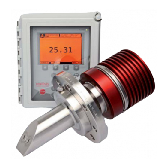
Chapter 2 – Product overview 2. Product overview The Vaisala K-PATENTSâ In-line Refractometer is an instrument for measuring liquid concentration in the process line. The measurement is based on the refraction of light in the process medium, an accurate and safe way of measuring liquid concentration. -
Page 12: Figure 2 Refractometer Equipment Pr-21-S
PR-21 Series User Guide IM-EN-PR21S-C Figure 1 Sensor LPH, model PR-21-S Figure 2 Refractometer equipment PR-21-S... -
Page 13: Safety
Chapter 2 – Product overview Model: INDICATING TRANSMITTER Product code: DTR-U-GP-AC S/N: T06802 Tag: 100-240 V AC, 50/60 Hz, 30 VA Made by VAISALA Oyj, Vantaa, Finland www.vaisala.com IP66 Dual transmitter label Figure 3 Labels 2.1 Safety This product has been tested for safety. Note the following precautions: WARNING! Only licensed experts may install electrical components. -
Page 14: Storage Conditions, Packaging And Transportation
PR-21 Series User Guide IM-EN-PR21S-C It is the user’s responsibility to follow manufacturer’s safety and operating instructions. The client’s organization has the responsibility to develop and maintain occupational safety and create a safety culture where individuals are expected to follow safety instructions at all times. -
Page 15: Figure 5 Image Detector System
Chapter 2 – Product overview The image detector output is a pulse train, as shown in Figure 5 (page 13). This number of high pulses corresponds to the position of the shadow edge in the optical image. The number of high pulses is a direct measure of the critical angle. The sensor processor card (E) receives the raw data from CCD element (C) and the temperature probe (F). -
Page 16: Mounting
PR-21 Series User Guide IM-EN-PR21S-C 3. Mounting 3.1 Choosing sensor mounting location The sensor is delivered with mounting guides attached. The sensor is designed to be installed directly in a process line. If the sensor is located outdoors, protect the sensor against direct exposure to sunlight and rain. -
Page 17: Figure 6 Mounting Guide 1/2
Chapter 3 – Mounting Figure 6 Mounting guide 1/2... -
Page 18: Figure 7 Mounting Guide 2/2
PR-21 Series User Guide IM-EN-PR21S-C Figure 7 Mounting guide 2/2... -
Page 19: Mounting Examples
Figure 9 (page 18), and Figure 10 (page 19). For flanged mounting, the user has to provide the counter flange. For clamp mounting Vaisala provides a weld-on ring. Flow cells can be supplied by Vaisala. Figure 8 Sandvik LPL and LPS... -
Page 20: Figure 9 Flange Lpl And Lps
PR-21 Series User Guide IM-EN-PR21S-C 63.50 63.50 LPL: DIN, JIS and ANSI 150 lbs or 300 lbs LPS: DIN, JIS and ANSI 150 lbs or 300 lbs Figure 9 Flange LPL and LPS... -
Page 21: Mounting Sensor
Chapter 3 – Mounting Figure 10 DIN, JIS and ANSI 150lbs or 300lbs flanges 3.3 Mounting sensor Follow these instructions when mounting the sensor. -
Page 22: Pipe Mounting Checklist
PR-21 Series User Guide IM-EN-PR21S-C Figure 11 Mounting procedure 1. Make sure the sensor is connected to the process line. 2. Identify the sensor by the serial number (a). 3. Check flow direction. If the fitting has a fixed flange, the bolt holes should allow proper flow alignment of the probe. -
Page 23: Checklist For Mounting In Tank, Vessel Or Large Pipe
Chapter 3 – Mounting 3. If the temperature varies along the process pipe, select the position with the highest process temperature. Then the risk of prism coating is minimized, because higher temperature means higher solubility and also lower viscosity. 4. Often the position with the highest process pressure (= after pump + before valve) has favorable flow conditions without sedimentation or air trapping risks. -
Page 24: Indicating Transmitter Dtr
PR-21 Series User Guide IM-EN-PR21S-C 4. Indicating transmitter DTR 4.1 Mounting indicating transmitter Warning Warning! The DTR does not have a built-in power Varování! DTR nemá vestavěný vypínač napájení. Po switch. The system is always powered on when připojení ke zdroji napájení je systém vždy zapnutý. connected to a power source. -
Page 25: Electrical Connections
Chapter 4 – Indicating transmitter DTR Mount the indicating transmitter indoors, preferably in an easily accessible, well-lit and dry area. Avoid vibration. Take interconnecting cable length into consideration when choosing the mounting location. The enclosure is mounted vertically on an upright surface (wall) using four mounting feet, see the following figure. -
Page 26: Connecting Sensor
PR-21 Series User Guide IM-EN-PR21S-C 4.2.2 Connecting sensor Old PR‑01‑S cables (model codes PR‑8001‑XXX) can be used if they are in good shape and shorter than 100 m (328 ft). Figure 13 Wiring of PR-21-S with DTR... -
Page 27: Connecting Indicating Transmitter
Chapter 4 – Indicating transmitter DTR More information ‣ Interconnecting cable (page 23) 4.2.3 Connecting indicating transmitter Warning Warning! Check that the power is off before opening Varování! Před otevřením předního panelu the front panel. If the green power indicator light is zkontrolujte, zda je napájení... - Page 28 PR-21 Series User Guide IM-EN-PR21S-C Warning Warning! Install the external power switch in Varování! Externí vypínač nainstalujte v souladu s accordance to the local installation requirements. místními požadavky na instalaci. Varoitus! Asenna ulkoinen virtakytkin paikallisten Figyelmeztetés! A külső tápkapcsolót a helyi asennusvaatimusten mukaisesti.
-
Page 29: Figure 14 Opening Indicating Transmitter Front Panel
Chapter 4 – Indicating transmitter DTR Figure 14 Opening indicating transmitter front panel Power indicator light Front panel screw Make sure that you mount an external power switch for the divert control unit that is close to the unit and easily reachable. Make sure that you mark it as a disconnecting device. The following figure shows the recommended external power switch, spare part nr PR‑10900. -
Page 30: Figure 15 External Power Switch
PR-21 Series User Guide IM-EN-PR21S-C 100 … 240 V AC / 50 … 60 Hz Figure 15 External power switch... -
Page 31: Figure 16 Motherboard (Ac Power)
Chapter 4 – Indicating transmitter DTR The following figure shows the motherboard of the indicating transmitter for AC power. Figure 16 Motherboard (AC power) -
Page 32: Figure 17 Motherboard (24 V Dc)
PR-21 Series User Guide IM-EN-PR21S-C The following figure shows the motherboard of the indicating transmitter for 24 V DC power. POWER Figure 17 Motherboard (24 V DC) The following table describes the terminals on the H1 interface card PR‑10701 and on the transmitter motherboard PR‑10600. -
Page 33: Power Terminals For Ac Power
Chapter 4 – Indicating transmitter DTR Terminal Usage Power, L (31), N (32), protective earth (33), 100 … 240 V AC, 50 … 60 Hz, 31 32 33 fuse with voltage 250 V AC, max. size 10 A and speed slow. An external power switch is mandatory. -
Page 34: Relay Connections
PR-21 Series User Guide IM-EN-PR21S-C 4.2.6 Relay connections Warning Warning! Connect only AC or DC power to relays. Varování! K relé připojte pouze střídavé nebo You can connect AC power to both relays or DC stejnosměrné napájení. Můžete připojit střídavé power to both relays, but never connect AC in one napájení... - Page 35 Chapter 4 – Indicating transmitter DTR Warning Warning! Multiple power sources. The relays are Varování! Více zdrojů napájení. Relé jsou napájena z powered from external circuits. externích obvodů. Varoitus! Useita virtalähteitä. Releet saavat virtaa Figyelmeztetés! Több áramforrás. A relék táplálása ulkoisista piireistä.
-
Page 36: Reset Button
PR-21 Series User Guide IM-EN-PR21S-C 4.2.7 Reset button You can reset and restart both the indicating transmitter DTR and the sensor by pushing the reset button. You can access the button through the cable hole in the front panel shield as shown in the following figure. -
Page 37: Prism Wash Systems
Chapter 5 – Prism wash systems 5. Prism wash systems Three alternatives of prism wash systems can be provided: 1. Steam wash with integral nozzle, see Prism wash with integral steam nozzle (page 36) 2. High-pressure water with integral nozzle, see Prism wash with integral high-pressure water nozzle (page 38) 3. -
Page 38: Prism Wash With Integral Steam Nozzle
Figure 20 (page 38) shows recommended components for a prism wash system with integral steam nozzle. The components are provided by Vaisala. The steam line should be equipped with a check valve (see Figure 20 (page 38)). If the process medium solidifies at ambient... -
Page 39: Figure 19 Mounting Of Integral Steam Nozzles With Din, Jis, Ansi And Sandvik Connections
Chapter 5 – Prism wash systems Figure 19 Mounting of integral steam nozzles with DIN, JIS, ANSI and Sandvik connections... -
Page 40: Prism Wash With Integral High-Pressure Water Nozzle
PR-21 Series User Guide IM-EN-PR21S-C Figure 20 Mounting summary of integral prism wash system Part Part specification Supplied by Indicating transmitter DTR Vaisala Sensor PR‑21‑S Vaisala Cable PR‑8023 between indicating transmitter and Vaisala sensor Shut‑off valve and steam trap PR‑3340‑230/110 Vaisala Check valve PR‑3303... - Page 41 43). High‑pressure pump Use Vaisala PR‑3602‑SP‑400 high pressure pump. The recommendation is to use 3 (3 phase) pumps with local voltages. Inlet water temperature should be warm, about +60 °C (+140 °F). Vaisala delivers high pressure pump with 8 m rubber high‑pressure hose.
-
Page 42: Figure 21 Mounting Drawing For Integral High-Pressure Wash System
PR-21 Series User Guide IM-EN-PR21S-C Figure 21 Mounting drawing for integral high‑pressure wash system Part Part specification Supplied by Indicating transmitter DTR Vaisala Sensor PR‑21‑xxx‑HPN Vaisala Cable between indicating transmitter and Vaisala sensor PR‑8230 Check valve R ¼ in PR‑3303 Vaisala High‑pressure hose 8 m (26.25 ft) -
Page 43: Figure 22 Wiring Drawing: High-Pressure Wash System For Water
Chapter 5 – Prism wash systems Figure 22 Wiring drawing: High‑pressure wash system for water... -
Page 44: Prism Wash With Flow Through Cells
PR-21 Series User Guide IM-EN-PR21S-C 5.4 Prism wash with flow through cells Figure 23 Prism wash with flow through cells... -
Page 45: Recommended Wash Pressures And Times
Chapter 5 – Prism wash systems Figure 24 Flow through cell nozzles 5.5 Recommended wash pressures and times To select the recommended wash pressure and wash time use the following table. -
Page 46: Table 2 Recommended Wash Pressures And Times
PR-21 Series User Guide IM-EN-PR21S-C Table 2 Recommended wash pressures and times Nozzle type Wash medium Wash time Min. above Max. above process pressure process pressure Integral nozzles steam 2 … 3 s 2 bar (30 psi) 6 bar (85 psi) ‑HPS pressure water 10 …... -
Page 47: Startup And Use
Chapter 6 – Startup and use 6. Startup and use 6.1 Startup 6.1.1 Initial check Main display for two sensors Main display for single sensor, concentration only Main display for single sensor, Main display for single sensor, concentration and temperature concentration and bar graph Figure 25 Main display alternatives 1. -
Page 48: Calibration Check
PR-21 Series User Guide IM-EN-PR21S-C 6. For a connected sensor, the diagnostic message at start-up is Normal operation or NO SAMPLE if the process pipe is empty. If another diagnostic message is shown instead, Diagnostic message priorities (page 94). 7. The TEMP value shows the current process temperature. 8. -
Page 49: Keyboard Functions
Chapter 6 – Startup and use More information ‣ Configuration and calibration (page 54) 6.2.1 Keyboard functions Number keys: The 10 number keys, minus sign, and decimal point are used to enter numerical parameters. They are also used for menu selections. ENTER key: The ENTER key is used to implement the selected (highlighted) menu command or to accept an entered value. -
Page 50: Display Setup
PR-21 Series User Guide IM-EN-PR21S-C P OWE R INSTRUMENTS Figure 26 DTR keyboard and Main menu for sensor B Press the key under the display. The display is not touch sensitive. 6.2.2 Display setup Selecting MENU / MENU A / MENU B or SENSOR A or SENSOR B (depending on your Main display format) in the Main display gives the menu display. -
Page 51: Figure 27 Display Setup Menu
Chapter 6 – Startup and use Figure 27 Display setup menu Main display format: As shown in Figure 25 (page 45), there are four different Main display formats: the dual sensor format shows information on both sensors while the three different single sensor formats show selected information on one sensor at a time. -
Page 52: Viewing System Information
PR-21 Series User Guide IM-EN-PR21S-C Display appearance: The 2 DISPLAY BACKLIGHT & CONTRAST can be selected from the Display setup menu, see Figure 27 (page 49). The values can be changed by using the arrow soft keys or alternatively a one digit input, for example 8 designates 80 % when adjusting contrast. -
Page 53: Viewing Sensor Status
Chapter 6 – Startup and use Figure 29 System description More information ‣ Ethernet connection specification (page 117) 6.4 Viewing sensor status Select SENSOR STATUS from the Main menu. 6.4.1 Optical image With the image detection algorithm the Optical image graph (See Figure 5 (page 13) explanation) should look like Figure 30 (page 52), right side. -
Page 54: Diagnostic Values
PR-21 Series User Guide IM-EN-PR21S-C Figure 30 Typical optical images Figure 31 A slope graph 6.4.2 Diagnostic values The values at the left of the graph are used for diagnostic purposes: • CONC is the final concentration value including field calibration adjustment, see Figure 40 (page 67). -
Page 55: Temperature Measurement
Chapter 6 – Startup and use • QF or Quality Factor is a value in the range of 0 to 200. The QF value depends on process medium optical properties. A typical good value is 100, but there are process media where 50 is acceptable. -
Page 56: Configuration And Calibration
PR-21 Series User Guide IM-EN-PR21S-C 7. Configuration and calibration All changes of configuration and calibration are made through the Calibration menu selected from the Main menu by 5 CALIBRATION. Password: It may be necessary to enter a password before proceeding to the Calibration menu. -
Page 57: Linear Damping
Chapter 7 – Configuration and calibration Figure 32 Exponential damping 7.1.2 Linear damping If the process has fast step changes, linear (fast) damping gives shorter settling time. In the linear damping (fast damping), the output is the running average of the signal during the damping time. -
Page 58: Slew Rate Limit
PR-21 Series User Guide IM-EN-PR21S-C Figure 33 Linear damping 7.1.3 Slew rate limit If the process signal has short erroneous high or low peaks, the slew rate limiting can be used to cut their effects. The slew rate damping limits the maximum change for the output signal in 1 s. -
Page 59: Configuring Output Signal Hold Functionality
Chapter 7 – Configuration and calibration Figure 34 Slew rate damping Avoid overdamping, the signal should not be made insensitive. 7.2 Configuring output signal hold functionality The refractometer can be configured to temporarily hold its measurement result in three different cases: 1. By using an external hold switch, see Configuring input switches (page 62). -
Page 60: External Hold
PR-21 Series User Guide IM-EN-PR21S-C 7.2.1 External hold When a switch input is configured for external hold functionality, see Configuring input switches (page 62), and the switch contact is closed, the measurement result is in hold. The measurement result is kept in hold until the switch contact is opened. A status message EXTERNAL HOLD is displayed. -
Page 61: Qf Threshold
Chapter 7 – Configuration and calibration Figure 35 Effect of tolerance time on output 7.2.4 QF threshold The QF threshold setting can be used to prevent the instrument from measuring when the image quality is below a certain limiting value. When QF value lower than the defined value, the image status changes to NO OPTICAL IMAGE after the defined tolerance time, see Tolerance time (page 58). -
Page 62: Hold And Signal Damping
PR-21 Series User Guide IM-EN-PR21S-C 7.2.6 Hold and signal damping The signal filtering (damping) is stopped during hold. The last filtered value is shown on the screen and set to the mA output (if the concentration output is configured). The following figure shows this behavior (gray areas represent the periods when the hold is active). -
Page 63: Figure 37 Relay Menu For Relay 1
Chapter 7 – Configuration and calibration Figure 37 Relay menu for relay 1 1. Select Menu > 5 CALIBRATION > 3 RELAYS. 2. Select the relay that you want to configure, either 1 RELAY 1 or 2 RELAY 2. 3. To assign the current relay to either sensor A or sensor B, select 1 SENSOR. The current assignment of the relay is shown at the bottom of the Relay menu display. -
Page 64: Configuring Input Switches
PR-21 Series User Guide IM-EN-PR21S-C 5. If you choose either low limit or high limit as relay function, you must define a limit source. To set the limit source, select Relay > 3 LIMIT SOURCE. Limit source selection: Function name Description NOT DEFINED Factory setting. - Page 65 Chapter 7 – Configuration and calibration 2. Select switch, 1, 2, 3 or 4, to be configured. The Switch menu shows the following options. 3. Select 1 SENSOR to assign the chosen switch to a given sensor. The selection line automatically goes to the currently valid setting. In the following figure, switch 1 has been assigned to sensor A.
-
Page 66: Configuring Ma Outputs
PR-21 Series User Guide IM-EN-PR21S-C 4. To set the switch function, select Switch > 2 FUNCTION. The current assignment of the switch is shown at the bottom of the Switch menu display. For example, in the previous figure, switch 1 is assigned to sensor A with function Wash stop. -
Page 67: Figure 38 Output Menu For Ma Output 1
Chapter 7 – Configuration and calibration • Select 5 CALIBRATION in the Main menu and enter password if necessary. Select 2 OUTPUTS in the Calibration menu. In the Outputs menu, select 5 mA OUTPUTS. • Select the mA output, 1 or 2, to get to the Output menu (as shown in the following figure) where the output can be configured. -
Page 68: Calibrating Concentration Measurement
PR-21 Series User Guide IM-EN-PR21S-C • 5 DEFAULT OUTPUT sets a mA default output value that the instrument returns to in certain malfunction situations. The value can be set to a low or high mA value, for example, 3.0 mA or 22 mA. The factory setting for default output is 3.4 mA. For a list of malfunctions that are affected, see Diagnostic message priorities (page 94). -
Page 69: Figure 40 Concentration Calibration Layers
Chapter 7 – Configuration and calibration Pt-1000 TEMP Sensor Indicating transmitter CHEMICAL CURVE CALC FIELD CALIBRATION DAMPING CONC mA OUTPUT Figure 40 Concentration calibration layers The information from the CCD element and the Pt-1000 temperature element. The position of the shadow edge, see Figure 88 (page 147), is described by a number called CCD and scaled 0 …... -
Page 70: Chemical Curve
A chemical curve is specific to the given process medium, for example, sucrose or sodium hydroxide. The set of parameters is given by Vaisala and should not be altered, except in case of changing to another process medium. The parameters can be changed by selecting 5 CALIBRATION from the Main menu, then, in the Calibration menu, 1 CHEMICAL &... -
Page 71: Field Calibration
Chapter 7 – Configuration and calibration 7.4.3 Field calibration Vaisala provides a field calibration service that adapts the calibration to the factory laboratory determinations based on the data supplied. The field calibration procedure should be made under normal process conditions using standard laboratory determinations of sample concentration. -
Page 72: Entering Field Calibration Parameters
Calibration using the process liquid must always be made in‑line. 7.4.4 Entering field calibration parameters Enter the field calibration parameters supplied by Vaisala by selecting 5 CALIBRATION from the Main menu, followed by 1 CHEMICAL & FIELD PARAMETERS and then 2 FIELD CALIBRATION PARAMETERS. -
Page 73: Configuring Prism Wash
Chapter 7 – Configuration and calibration The value of the bias parameter f00 is added to the concentration value: NEW CONC = OLD CONC + f00. 7.5 Configuring prism wash In some applications the process flow does not keep the prism clean because of sticky process medium or low flow velocity. - Page 74 PR-21 Series User Guide IM-EN-PR21S-C For safety reasons two sensors never wash simultaneously. If the manual wash button for sensor A is pressed while sensor B is washing, the wash cycle for sensor A is started after B has finished. Similarly, if the interval time for sensor B elapses when A is washing, the wash for sensor B is delayed until A has finished.
-
Page 75: Figure 43 Wash Logic
Chapter 7 – Configuration and calibration sensor washing? MANUAL been WASH pressed? Remote wash requested? Wash interval reached? Temp limit active? Temp above limit? Message Figure 43 Wash logic... - Page 76 PR-21 Series User Guide IM-EN-PR21S-C Remote wash is triggered at the closing of the switch. If the switch is held closed, only one wash cycle is carried out. The wash is inhibited if there is no sample, no sensor or the sensor cannot measure correctly.
-
Page 77: Figure 44 Wash Cycle
Chapter 7 – Configuration and calibration Precondition enabled? Precondition 1 s wait Start washing Wash auto-cut enabled? nD < nD limit? Wash time reached? Wash time reached? Stop washing Recovery Figure 44 Wash cycle More information ‣ Troubleshooting messages (page 89) -
Page 78: Setting Prism Wash Parameters
PR-21 Series User Guide IM-EN-PR21S-C 7.5.2 Setting prism wash parameters To set the prism wash parameters for a given sensor, first select the sensor, then select 5 CALIBRATION from the Main menu, and then 4 PRISM WASH. This menu contains the alternatives (factory settings are given in parentheses): Parameter Value... -
Page 79: Mechanical Zero Adjustment
Chapter 7 – Configuration and calibration To activate (or deactivate) a temperature limit, choose 7 TEMP LIMIT ACTIVATION and then the appropriate command in the menu. To set a low temperature limit, choose 8 TEMP LIMIT VALUE °C and enter the temperature (in °C) where the limit should be. -
Page 80: Sensor Rangeability
PR-21 Series User Guide IM-EN-PR21S-C B=adjusting screw A=locking screw C=fiber optics holder Figure 45 Mechanical zero adjustment 7.6 Sensor rangeability The sensor is made in two versions: Probe tip angle is either 50 degrees or 57 degrees. The value is stamped on the probe tip. The rangeability of the two sensor versions is described in the following figure. -
Page 81: Regular Maintenance
Chapter 8 – Regular maintenance 8. Regular maintenance The need for regular maintenance is minimal, due to the construction with no moving parts, no mechanical adjustments and with a solid-state light source. The following rules apply: • Keep the sensor head and the indicating transmitter clean and dry. •... -
Page 82: Disassembling The Sensor
PR-21 Series User Guide IM-EN-PR21S-C 8.3.1 Disassembling the sensor 1. To remove the cover, open the clamp using a 11 mm wrench. Lift cover carefully, the O‑ring seal causes some friction. 2. Remove the processor card. All connectors have latches. 3. Remove the image detector module. a. -
Page 83: Removing Electronic Cards Pr-10301 And Pr-10201
Chapter 8 – Regular maintenance 4. Remove the light source module. a. Remove screw B. b. Pull out the light source module. The hole C should always be empty. c. Remove the emitter assembly that is locked by screw D. 5. -
Page 84: Troubleshooting
PR-21 Series User Guide IM-EN-PR21S-C 9. Troubleshooting 9.1 Hardware Warning Warning! Hazardous voltage, contact may cause Varování! Nebezpečné napětí, kontakt může electric shock or burn. Beware of the live wires in the způsobit úraz elektrickým proudem nebo popálení. lower right-hand corner of the H1 interface card. Dejte si pozor na vodiče pod napětím v pravém dolním rohu karty rozhraní... -
Page 85: Figure 48 Transmitter Card Positions
Chapter 9 – Troubleshooting To troubleshoot refractometer hardware problems, it is often important to localize the different cards inside the DTR. The Diagnostic LEDs on the cards help solve the problems and give an indication on whether a connection is good. Figure 48 Transmitter card positions Power indicator light Transmitter processor card PR‑10500... -
Page 86: Figure 49 Motherboard Pr-10600 And H1 Interface Card Pr-10701
PR-21 Series User Guide IM-EN-PR21S-C Figure 49 Motherboard PR‑10600 and H1 interface card PR‑10701... -
Page 87: Blank Display
Chapter 9 – Troubleshooting 9.1.1 Blank display Is Power indicator light on? Processor See figure on next page to Power supply card LEDs troubleshoot power supply. problem blinking? Processor card PR-10500 or Front panel bad. Processor Processor card card LEDs PR-10500 bad. blinking? Contrast and backlight are reset by pressing . -
Page 88: Diagnostic Leds
PR-21 Series User Guide IM-EN-PR21S-C Important safety considerations +24 V - Always switch off the mains before Power supply OK disconnecting or reconnecting cables, modules, and similar - Beware of the high voltage terminals 34 and 35 Mains Have it fixed Measuring instructions - Use a DMM (Digital Multimeter) to measure the voltage... -
Page 89: Table 4 Diagnostic Leds
Chapter 9 – Troubleshooting Table 4 Diagnostic LEDs Status Indication See section Front panel Green LED DTR power is on; processor card Blank display PR‑10500 is active. (page 85) Transmitter processor card PR‑10500 2 yellow LEDs Blinking Processor card OK. Transmitter motherboard PR‑10600 Yellow LED (D17) Blinking Motherboard processor working. -
Page 90: Display Unreadable
PR-21 Series User Guide IM-EN-PR21S-C Transmitter processor card POWER DISPLAY 24 V/3 V KEYBOARD 3 V DC 24 V DC Power supply module DC/DC Relay 1 Relay 2 mA outputs Transmitter motherboard H1 interface card Figure 52 Diagnostic LED functions 9.1.3 Display unreadable If the display is unreadable because of extreme display backlight and contrast settings or wrong display language, you can perform a display reset. -
Page 91: Troubleshooting Messages
Chapter 9 – Troubleshooting 4. Hold down the decimal point key until the DTR has started completely and you see the main display. The reset on the display language is temporary and the language returns to original next time the DTR is powered off, except if the language is permanently changed through the display settings menu. - Page 92 PR-21 Series User Guide IM-EN-PR21S-C Problem Cause Corrective action Message SHORT-CIRCUIT The most likely cause of these Check that the cable is undamaged messages is a problem in the cable and replace it if necessary, then The current in the cable to the connecting the sensor in question turn the DTR off and back on.
-
Page 93: Figure 48
Chapter 9 – Troubleshooting Problem Cause Corrective action Message HIGH TRANSMITTER The temperature of the To read this temperature, select 3 TEMP motherboard of the Indicating SENSOR STATUS from the Main transmitter exceeds 60 °C (140 °F). menu and check DTR TMP. If the warning persists, move the transmitter to a cooler place (for example out of the sun). - Page 94 PR-21 Series User Guide IM-EN-PR21S-C Problem Cause Corrective action Message NO OPTICAL IMAGE The optical image can be seen from selecting 3 SENSOR STATUS at the Main menu, see Optical image (page 51). There are several possible causes: 1. The prism is heavily coated, see Prism coating (page 35).
-
Page 95: Table 7 Wash Troubleshooting
Chapter 9 – Troubleshooting Problem Cause Corrective action Message TEMP MEASUREMENT Indicates faulty temperature Replace the temperature element. FAULT element. A difference to some other process temperature measurement is not a fault. PR‑23 measures the true temperature of the prism surface. -
Page 96: Diagnostic Message Priorities
PR-21 Series User Guide IM-EN-PR21S-C More information ‣ Wash cycle (page 71) 9.1.5 Diagnostic message priorities The messages are listed in descending order of priority. For example, if both NO OPTICAL IMAGE and TEMP MEASUREMENT FAULT are activated, only NO OPTICAL IMAGE displays. - Page 97 Chapter 9 – Troubleshooting Message Instrument OK Returns to default mA Conc Temp PRISM WASH FAILURE PRISM WASH WARNING NO SENSOR NORMAL OPERATION...
-
Page 98: Indicating Transmitter Dtr Specifications
Model: INDICATING TRANSMITTER Product code: DTR-U-GP-AC S/N: T06802 Tag: 100-240 V AC, 50/60 Hz, 30 VA Made by VAISALA Oyj, Vantaa, Finland www.vaisala.com IP66 Figure 53 Indicating transmitter serial number labels 10.1 Compatibility The indicating transmitter DTR is only compatible with the PR-21-S refractometers and the PR-23 range. -
Page 99: Model Code
Chapter 10 – Indicating transmitter DTR specifications 10.2 Model code 10.2.1 Indicating transmitter model codes Table 8 Indicating transmitter DTR and STR model codes Model Description Indicating transmitter (connectivity for two sensors) Indicating transmitter (connectivity for one ‑IA/‑IF/‑CI sensor) Cable connection ½ in NPT type conduit hubs for CSA certified transmitter M20x1.5 metric cable glands for general purpose Electrical classification General purpose... -
Page 100: Transmitter Parts List
PR-21 Series User Guide IM-EN-PR21S-C 10.3 Transmitter parts list 7,1 7,2 15,2 15,1 Figure 54 Indicating transmitter DTR and STR parts (STR-specific parts in italics) 10.4 Specifications 10.4.1 Indicating transmitter specifications Table 10 Indicating transmitter specifications Feature Specification Display 320 x 240 pixel graphical LCD with LED backlight Keypad 18 membrane keys... - Page 101 Chapter 10 – Indicating transmitter DTR specifications Feature Specification Current output Two independent current sources, 4 … 20 mA, max. load 1000 Ω, galvanic isolation 1500 V DC or AC (peak), hold function during prism wash. AC power supply AC input 100 … 240 V AC, ±10%, 50/60 Hz / 30 VA, fuse voltage 250 V AC, fuse max.
-
Page 102: Interconnecting Cable Specifications
PR-21 Series User Guide IM-EN-PR21S-C 10.4.2 Interconnecting cable specifications Table 11 Interconnecting cable specifications Feature Specification Cable IEC 61158‑2 compliant two-wire cable: two signal wires and shield copper area 0.8 mm (18 AWG) cable resistance 24 Ω/km (per wire) cable attenuation 3.0 dB/km @ 28 kHz Cable length Standard 10 m (33 ft), max. -
Page 103: Sensor Specifications
Chapter 11 – Sensor specifications 11. Sensor specifications 11.1 Model codes Table 12 PR‑21‑S models Model Description PR‑21‑S Sensor Refractive index range limits Low range, R.I. 1.320 … 1.460 (max span = 0.11) High range, R.I. 1.380 … 1.530 (max span = 0.1) Process connection Sandvik L‑clamp, 88 mm ‑L... -
Page 104: Table 13 Transmitter Models For 100
PR-21 Series User Guide IM-EN-PR21S-C Table 13 Transmitter models for 100 … 240 V AC Model Description Indicating transmitter (connectivity for two sensors) Indicating transmitter (connectivity for one ‑IA sensor) Cable connection ½ in NPT‑type conduit hubs ‑U M20x1.5 metric cable glands ‑M Electrical classification General purpose... -
Page 105: Pr-21-S Part List
Chapter 11 – Sensor specifications Model Description ‑_ _ _ Specify cable length in meters with 10 m (33 ft) increments. Maximum length is 200 m (660 ft) PR‑8021 Cable connector for PR‑21‑S for ‑GP and ‑IA sensors PR‑8021‑FM Cable connector for PR‑21‑S for FM sensors New cable connector needed for PR‑21‑S new sensor or PR‑21 upgrade 11.2 PR-21-S part list Figure 55 Probe parts... - Page 106 PR-21 Series User Guide IM-EN-PR21S-C Item Pcs. Part No. Description PR‑7725 Sensor wetted parts for Sandvik 50 LPS HPY PR‑7726 Sensor wetted parts for Sandvik 57 LPS HPY PR‑7727 Sensor wetted parts for Sandvik 50 LPS YPY PR‑7728 Sensor wetted parts for Sandvik 57 LPS YPY PR‑3503 Sandvik clamp FCLC‑316L‑99.9‑S‑T PN25 PR‑3504...
-
Page 107: Sensor Pr-21-S
Chapter 11 – Sensor specifications 11.3 Sensor PR-21-S Figure 56 Sensor Item Pcs. Part No. Description Probe with Sandvik L‑clamp Prism PR‑5005 Prism holders AISI 316 L PR‑5006 Prism holder screws DIN912 M5x12 A4-80 Teflon pads PR‑5046 Spinel prism + Kalrez 6375 gaskets + support rings + Teflon pads + screws DIN912 M5x12 A4‑80 PR‑8101... - Page 108 PR-21 Series User Guide IM-EN-PR21S-C Item Pcs. Part No. Description PR‑5011 O‑ring seal 108x3 Nitrile PR‑5013 Thermal insulator 80/90 x 1.7 Teflon Screws DIN 912 M5 x 30 A2/A4 Metallic standoff screw PR‑8110 Sensor cover PR‑5012 V‑clamp CA 0600/11‑130mm‑S‑40 PR‑9108 Dryer PR‑9109 Dryer support...
-
Page 109: Standard Specifications
Chapter 11 – Sensor specifications Item Pcs. Part No. Description Plug‑in light source module PR‑7507 Plug‑in light source module LP 50 PR‑7508 Plug‑in light source module LP 57 10.1 PR‑5211 O‑ring seal 16x2 FEP / Viton 10.2 Screw DIN 912 M3 x 30 A2 10.3 Spring 10.4... -
Page 110: Pr-21-S Process Refractometers In Potentially Explosive Atmosphere
The PR‑21 refractometer series can be used in locations with potentially explosive atmosphere with following modifications, made by Vaisala. The PR‑21‑…‑FM refractometer is certified by Factory Mutual Research Corporation, Certificate No. 3050975. Equipment Ratings: Nonincendive for use in Class I, Division 2, Groups A, B, C &... -
Page 111: Figure 57 Refractometer System Pr-21
Chapter 11 – Sensor specifications Figure 57 Refractometer system PR‑21‑…‑FM The FM‑certified sensors PR‑21‑S‑…‑FM are identified by the sensor nameplate. The indicating transmitter is a standard DTR. -
Page 112: Intrinsically Safe Refractometers Pr-21
PR-21 Series User Guide IM-EN-PR21S-C Figure 58 FM nameplate 11.6 Intrinsically safe refractometers PR-21-…-IA Hazardous locations are places where a possibility of fire or explosion exists because of flammable gases, vapors or fine dust. Zone0: An area in which an explosive gas-air mixture is continuously present or present for long periods of time. -
Page 113: Equipment
Chapter 11 – Sensor specifications Only trained service personnel of Vaisala and its representatives are permitted to service the intrinsically safe PR‑21‑…‑IA refractometer. Servicing must be done according to separate instructions defined by Vaisala and must be reported to Vaisala. -
Page 114: Figure 60 Ia Nameplate
PR-21 Series User Guide IM-EN-PR21S-C Figure 60 IA nameplate An intrinsically safe sensor has a different processor card and a different terminator card than a standard sensor, other parts are as in standard sensor (see earlier in this chapter for full parts list). -
Page 115: Figure 61 Intrinsically Safe Parts
Chapter 11 – Sensor specifications Figure 61 Intrinsically safe parts WARNING! Do not replace any part of an intrinsically safe sensor with a standard sensor part. Contains lightmetals Ignition hazard! Avoid impact! Figure 62 Warning sticker... -
Page 116: Intrisincally Safe Mounting
PR-21 Series User Guide IM-EN-PR21S-C WARNING! If the sensor cover is made of aluminum, the refractometer sensor can cause ignition if it hits other metal parts during the installation. An aluminum sensor cover must have a sticker warning about this possibility. 11.6.2 Intrisincally safe mounting Choose the mounting location of the sensor, the isolator/barrier unit and the indicating transmitter so that they are protected from sudden impact and friction. -
Page 117: Figure 63 Intrinsically Safe Wiring, Pr-21-S
Chapter 11 – Sensor specifications Figure 63 Intrinsically safe wiring, PR‑21‑S‑…‑IA Cables:... -
Page 118: Isolator/Barriers
PR-21 Series User Guide IM-EN-PR21S-C • 10 m (33 ft) cable, part number PR‑8230‑010, connecting the Indicating transmitter STR and the Isolator unit. The maximum cable length is 100 m (330 ft). • 10 m (33 ft) power cable, part number PR‑8250‑010, connecting the Indicating transmitter STR and the Isolator unit, part number PR‑8250‑010. -
Page 119: Ethernet Connection Specification
DTR. This document gives all the specifications necessary to write a communications program for downloading purposes. It is also possible to get a ready-to-install communications software from Vaisala. 12.1 Cable requirements and connection 12.1.1 Ethernet cable specification... -
Page 120: Figure 66 Connecting Dtr To Lan
PR-21 Series User Guide IM-EN-PR21S-C P OWE R PRO C ESS INSTRUMENTS S traight-through cable Figure 66 Connecting DTR to LAN If you are connecting the DTR to a hub or switch or WLAN access point, please consult the user guide of your hub/switch/access point for the correct cable type, as shown in the following figures. -
Page 121: Connecting Ethernet Cable
Chapter 12 – Ethernet connection specification Check media P OWE R converter manual Fiber Media Media for Ethernet converter converter cable type PRO C ESS INSTRUMENTS Figure 69 Using fiber optics Ethernet 12.1.2 Connecting Ethernet cable To connect the Ethernet cable to the DTR, open the DTR’s enclosure cover, loosen the front panel screw and open the front panel. - Page 122 PR-21 Series User Guide IM-EN-PR21S-C Warning Warning! Check that the power is off before opening Varování! Před otevřením předního panelu the front panel. If the green power indicator light is zkontrolujte, zda je napájení vypnuto. Pokud svítí on, there is still power in the system. To completely zelená...
-
Page 123: Connection Settings
Chapter 12 – Ethernet connection specification Figure 70 Ethernet connector on underside of front panel The DTR has automatic speed negotiation, and automatically finds out what the optimal speed for the connection is and chooses accordingly, either 10 Mbit/s or 100 Mbit/s speed. 12.2 Connection settings 12.2.1 IP settings for DTR The DTR uses the IP protocol to communicate over the Ethernet. -
Page 124: Ip Settings For Stand-Alone Computer
PR-21 Series User Guide IM-EN-PR21S-C The DTR address is changed manually through the Calibration menu through the following path: 5 Calibration > 2 Outputs > 6 Network Type the new IP address and press Enter to change the address. 12.2.2 IP settings for stand-alone computer If you connect a non-networking (stand-alone) computer directly to a DTR with a cross-over cable, the easiest solution is to check the computer’s network settings and conform the DTR’s settings to it. -
Page 125: Testing Ethernet Connection
Chapter 12 – Ethernet connection specification You may have to connect the cross-over cable and power on the DTR before your computer generates an IP address for the Ethernet connection (computer reboot may also be required). The connection does not work if the computer and the DTR have exactly the same IP address. -
Page 126: Troubleshooting Connection
PR-21 Series User Guide IM-EN-PR21S-C Figure 72 Ping OK 12.3.1 Troubleshooting connection Figure 73 Ping error message If you get a ping error message, check your connections. Open the DTR cover and front panel and check the diagnostic LEDs of the Ethernet connector, see Connecting Ethernet cable (page 119). -
Page 127: Instrument Homepage
Chapter 12 – Ethernet connection specification Keep both the DTR and your computer powered while you check the diagnostic LEDs. If both LED lights are turned off, check the following: • Both the DTR and the device in the other end of the cable are powered on •... -
Page 128: Remote Panel
PR-21 Series User Guide IM-EN-PR21S-C Figure 74 Instrument homepage open in browser Opening the instrument homepage 1. Establish a working Ethernet connection to the DTR. 2. Start your preferred web browser (for example Firefox, Edge, Safari, Opera or Chrome). 3. Type the DTR IP address to the address bar. The DTR IP address for a factory-set DTR it is http://192.168.23.254/ (the address used... -
Page 129: Sensor Verification Certificate
The main purpose of the Ethernet connection is to collect measurement data from the instrument. To program a downloading facility, see the specifications in the following sections. Vaisala guarantees that the specifications are correct, but cannot assume any responsibility or provide support for software. 12.5.1 Communication protocol The communication protocol is based on UDP/IP to port 50023. - Page 130 PR-21 Series User Guide IM-EN-PR21S-C • (any): request data (depends on the request) • (any): fill-in data The maximum size of the message is 1472 octets (bytes). The packet number is echoed back by the DTR, but not processed in any way. The packet numbers do not have to be sequential, any 32-bit value is valid.
-
Page 131: Request-Response Pair Specification
Chapter 12 – Ethernet connection specification The server (DTR) may send the response keys in any order. It will send the mandatory keys of the specific request, but it may omit any other keys. The server may also send keys that are not specified in this document, but the client (computer) may ignore them. - Page 132 PR-21 Series User Guide IM-EN-PR21S-C Specification Description Request ID Request data Response key The DTR information query 0x00000002 (none) • *DTRserial: string, information gives the basic information of DTR serial number the DTR assembly. • *ProcessorSerial: string, processor card serial number •...
-
Page 133: Error Message Specification
Chapter 12 – Ethernet connection specification Specification Description Request ID Request data Response key Measurement The measurement result query 0x00000004 0x00000000 • Status: string, sensor results gives the measured and (sensor A) status message calculated measurement values • Slope: float, image 0x00000001 from the chosen sensor. - Page 134 PR-21 Series User Guide IM-EN-PR21S-C There may also be error-dependent extra keys. Other error codes may be returned. 0x00000003 is to be handled as unknown request. Codes with higher numbers refer to internal errors; contact Vaisala for more information on these.
-
Page 135: Sensor Verification
In cases where no such standards exist, the basis used for calibration must be documented. Vaisala verifies the calibration of all delivered instruments according to a procedure similar to the one described in Refractive index n D verification (page 133). -
Page 136: Handling R.i. Liquids
As the specified accuracy of PR‑21‑S is ±0.0004, then the representative level is the root sum square of the three accuracy specifications, that is ±0.0006. Vaisala provides a set of standard R.I. liquids, PR‑2000, containing these five liquids. The set can be ordered directly from Vaisala or through your nearest representative. -
Page 137: Figure 77 Verification, Pre-Verificaton Checks
Chapter 13 – Sensor verification Figure 77 Verification, pre-verificaton checks When you are finished with the preparations, press CONTINUE (right-most soft key) to start the verification process. The verification itself is done by the refractometer system. Follow the instructions on screen and apply one RI liquid at a time on the sensor and press VERIFY (right-most soft key). -
Page 138: Figure 79 Typical Optical Images
PR-21 Series User Guide IM-EN-PR21S-C Figure 79 Typical optical images A verification data collection method is implemented in the DTR. The instrument measures each verification data point ten times and uses the average of these measurements. Measuring each verification liquid takes approximately 10 s, during which the measurement progress display is shown, as shown in the following figure. -
Page 139: Sensor Verification Certificate
Chapter 13 – Sensor verification Figure 81 Verification completed successfully (here only with one RI liquid) The sensor verification concerns only the refractive index n measurement. The calculation of concentration from n and process temperature TEMP is not included, see Calibrating concentration measurement (page 66). -
Page 140: Figure 82 Instrument Verification Page Open In Browser
PR-21 Series User Guide IM-EN-PR21S-C Figure 82 Instrument verification page open in browser When you have performed a verification on a sensor, refresh the verification page to view the newest results. The date given on the verification page is the page load date, not necessarily the verification date. -
Page 141: Figure 83 Instrument Verification Certificate
Chapter 13 – Sensor verification r e t c i f i t a p t t s . f PROCESS REFRACTOMETER PR-23 Sensor verification Page loaded on February 2, 2009 at 03:19:28 PM Sensor information Serial number: R05676 Test results Nominal nD Measurement Sensor... -
Page 142: Corrective Action
(available in Appendix C) and send it to your nearest representative or email the collected information to helpdesk@vaisala.com and wait for further instructions. For the sensor verification form collect data from the Verification step 2 display and the Verification results display. -
Page 143: Figure 85 Finding Verification Information For Sensor Verification Form
Chapter 13 – Sensor verification Figure 85 Finding verification information for sensor verification form... -
Page 144: Regulatory Compliance And Certifications
PR-21 Series User Guide IM-EN-PR21S-C 14. Regulatory compliance and certifications 14.1 EC Declaration of Conformity for PR-21 series of refractometers The following Declaration of Conformity confirms compliance with the applicable EU/EEA requirements and applies to all Vaisala K-PATENTSâ PR‑21 refractometer products:... - Page 145 – Part 1: General requirements EN 61326-1:2013 Electrical equipment for measurement, control and laboratory use – EMC requirements – intended for use in industrial locations Signed for and on behalf of Vaisala Oyj, in Vantaa, on 1 September 2019 ______________________________________ Jukka Lyömiö...
-
Page 146: Declaration Of Conformity For Pr-21
PR-21 Series User Guide IM-EN-PR21S-C 14.2 Declaration of Conformity for PR‑21‑…‑IA models (ATEX) The following Declaration of Conformity confirms compliance with the European ATEX requirements and applies to Vaisala K-PATENTSâ PR‑21‑…‑IA refractometer products:... - Page 147 – EMC requirements – intended for use in industrial locations Notified body VTT Expert Services Ltd (number 0537) has issued EU-type examination certificate VTT 13 ATEX 052X for this product. Signed for and on behalf of Vaisala Oyj, in Vantaa, on 1 September 2019 ______________________________________ Jukka Lyömiö...
-
Page 148: Appendix A: Principle Of Measurement
IM-EN-PR21S-C Appendix A. Principle of measurement The Vaisala K‑PATENTSâ in‑line refractometer determines the refractive index n of the process solution. It measures the critical angle of refraction using a yellow LED light source with the same wavelength (589 nm) as the sodium D line (hence n ). -
Page 149: Figure 87 Optical Images
Appendix A – Principle of measurement The refractive index n changes with the process solution concentration and temperature. For most solutions the refractive index increases when the concentration increases. At higher temperatures the refractive index is smaller than at lower temperatures. From this follows that the optical image changes with the process solution concentration as shown in the figure below. -
Page 150: Appendix B: Pr-21 Sensor Verification Form
PR-21 Series User Guide IM-EN-PR21S-C Appendix B. PR-21 sensor verification form Fill in this form and email it to helpdesk@vaisala.com or to your local service representative. Sensor serial no: Customer: Address: Email: Date: Verification made by: Table 18 Verification results display Sample... -
Page 151: Appendix C: Field Calibration Form
Appendix C – Field calibration form Appendix C. Field calibration form Fill in this form and email it to helpdesk@vaisala.com or to your local service representative. Refractometer serial no: Refractometer model: Customer: Address: Email: Sample description: Solvent (water/other): Laboratory method: Date:... -
Page 152: Appendix D: Dtr Command Selection Tree
PR-21 Series User Guide IM-EN-PR21S-C Appendix D. DTR command selection tree SENSOR A/B MAIN MENU VERIFICATION SYSTEM mA OUTPUTS RELAYS DESCRIPTION SWITCHES PRISM WASH CHEMICAL CURVE PARAMETERS FIELD CALIBRATION NETWORK SENSOR nD CALIBRATION FIELD SAMPLE SENSOR RESTART SENSOR STATUS SLOPE WASH WASH DUAL SENSOR MAIN DISPLAY FORMAT... -
Page 153: Appendix E: Str/Divert Mode Command Selection Tree
Appendix E – STR/Divert mode command selection tree Appendix E. STR/Divert mode command selection tree MENU VERIFICATION SYSTEM mA OUTPUTS RELAYS DESCRIPTION SWITCHES PRISM WASH CHEMICAL CURVE PARAMETERS FIELD CALIBRATION NETWORK SENSOR nD CALIBRATION FIELD SAMPLE SENSOR RESTART SENSOR STATUS SLOPE WASH WASH MAIN DISPLAY FORMAT... - Page 154 PR-21 Series User Guide IM-EN-PR21S-C...
-
Page 155: Warranty
Conditions of Sale for details of the warranty for each product. Technical support Contact Vaisala technical support at helpdesk@vaisala.com. Provide at least the following supporting information as applicable: • Product name, model, and serial number •... - Page 158 www.vaisala.com...
Need help?
Do you have a question about the K-PATENTS PR-21 Series and is the answer not in the manual?
Questions and answers