Table of Contents
Advertisement
Quick Links
Advertisement
Table of Contents
Troubleshooting

Related Manuals for Vaisala K-PATENTS PR-21-S


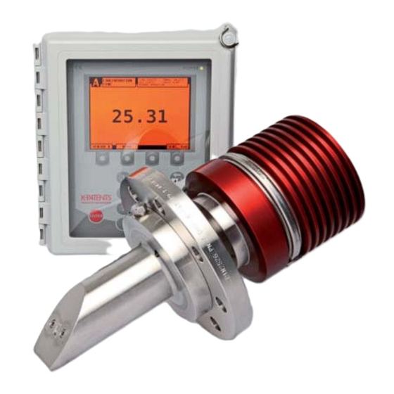
Summary of Contents for Vaisala K-PATENTS PR-21-S
- Page 1 IM-EN-PR21S-A Instruction Manual Vaisala K-PATENTS® Process Refractometer PR-21-S...
- Page 2 PR-21-S instruction manual...
- Page 3 Conditions of Sale for details of the warranty for each product. Technical support Contact Vaisala technical support at helpdesk@vaisala.com. Provide at least the following supporting infor- mation: • Product name, model, and serial number •...
-
Page 5: Table Of Contents
Table of contents Introduction ............1 Standard specifications . - Page 6 5.4.2 Diagnostic values ..........5.4.3 Temperature measurement .
- Page 7 8.1.7 Message ........75 HIGH SENSOR HUMIDITY 8.1.8 Message .
- Page 8 PR-21-S instruction manual 11.1.2 Connecting the Ethernet cable ....... . . 11.2 Connection settings .
-
Page 9: Introduction
1 Introduction 1 Introduction ® The Vaisala K-PATENTS inline refractometer is an instrument for measuring liquid concentration in the process line. The measurement is based on the refraction of light in the process medium, an accurate and safe way of measuring liquid concentration. - Page 10 A serial output is also available as a standard. Tag: 100-240 V AC, 50/60 Hz, 30 VA Made by VAISALA Oyj, Vantaa, Finland ial Number (S/N) label (Figure 2.11) on the Indicating transmitter front panel and by www.vaisala.com IP66 sor label (Figure 2.10, Figure 2.12), e.g.
-
Page 11: Standard Specifications
1 Introduction 1.1 Standard specifications SPECIFICATIONS Refractive Index range: Low range R.I. 1.320...1.460 High range R.I. 1.380...1.530 Max span: R.I. 0.120 Sensor PR-21-S with Sandvik clamp Accuracy: Typically ± 0.1% by weight (depending on the process medium). 14,3 Repeatability and stability correspond to accuracy. Speed of response: 1.0 s undamped, damping time selectable up to 5 min Calibration:... -
Page 12: Model Code
PR-21-S instruction manual 1.1.1 Model code Model and description Model PR-21 = Sensor PR-21 Refractive Index range limits 50 = Low range, R.I. 1.320..1.460 57 = High range, R.I. 1.380..1.530 Process connection -L = Sandvik L-clamp, 88 mm -D = DIN-flange 2656, PN 25, DN 80 -A = ANSI-flange 150 psi, 3 inch -J = JIS-flange, 10K 80 A Sensor wetted parts material... - Page 13 1 Introduction Model and description Model DTR = Indicating transmitter (connectivity for two sensors) STR = Indicating transmitter (connectivity for one -IA sensor) Cable connection -U = ½inch NPT-type conduit hubes -M = M20x1.5 metric cable glands Electrical classification -GP = General purpose Transmitter options (A) -DC = Power supply 24 V DC (A) Note standard power supply is 100-240 VAC 50/60 Hz...
- Page 14 PRICE LIST PR-21-S 2(2) Area: EURO Currency: EURO Effective: June 17th , 2013 PR-21-S instruction manual Replaces: PRELIMINARY PROCESS REFRACTOMETER PR-21-S-LPH Model and Description Model PR-21-S = Sensor PR-21-S Refractive Index range limits 50= Low range R.I. 1.320..1.460 max. span R.I = 0.13 57= High range R.I.
-
Page 15: Principle Of Measurement
1.2 Principle of measurement The K-Patents inline refractometer sensor determines the refractive index n of the process solution. It measures the critical angle of refraction using a yellow LED light source with the same wavelength (580 nm) as the sodium D line (hence n ). -
Page 16: General Safety Considerations
PR-21-S instruction manual 1.3 General safety considerations The process medium may be hot or otherwise hazardous. Use shields and protective clothing adequate for the process medium - do not rely on avoiding contact with the process medium. Precautions when removing a standard sensor from the process line : •... -
Page 17: Inline Refractometer Sensor
2 Inline refractometer sensor 2 Inline refractometer sensor 2.1 Sensor description 2.4. SENSOR DESCRIPTION In the process refractometer sensor (Figure 2.1) the measurement prism (A) is flush In the K-Patents Process Refractometer Sensor (Figure 2.40) the measurement prism (A) is flush mounted mounted in the oblique surface near the tip. -
Page 18: Mounting
PR-21-S instruction manual 2.2 Mounting 2.2.1 Sensor location The sensor is delivered with mounting guides attached, Figure 2.3 and Figure 2.4. The sensor is designed for being installed directly in a process line. If the sensor is located out of doors, some basic protection against direct exposure to sunlight and rain should be provided. - Page 19 2 Inline refractometer sensor 2 Inline refractometer sensor 2.2.2 PR-23 mounting guide Figure 2.3 Mounting guide 1/2...
- Page 20 PR-21-S instruction manual Figure 3.10 Mounting guide. Figure 2.4 Mounting guide 2/2 INSTRUCTION MANUAL FOR K-PATENTS PR-01-S (-AX/FM/CS) DOCUMENT/REVISION No. INM 1/14 Effective: May 15, 2009...
-
Page 21: Mounting Examples
Examples for different mounting option are given in Figure 2.5 (Sandvik mounting STD, LPL and LPS) and Figure 2.6, Figure 2.7 (Flange mounting). For flanged mounting, the user has to provide the counter flange. For clamp mounting Vaisala provides a weld-on ring. Flow cells can be supplied by Vaisala. - Page 22 PR-21-S instruction manual Figure 2.5 Sandvik STD, LPL and LPS...
- Page 23 2 Inline refractometer sensor 63.50 63.50 STD: DIN, JIS and ANSI 150 lbs or 300 lbs LPL: DIN, JIS and ANSI 150 lbs or 300 lbs 63.50 LPS: DIN, JIS and ANSI 150 lbs or 300 lbs Figure 2.6 Flange STD, LPL and LPS...
- Page 24 PR-21-S instruction manual Sheet 2/2 DN 80 PN 40 ANSI 150lbs 152.40 190.50 ANSI 300lbs JIS 80A 10k 168.10 209.50 General tolerances Drawing description ISO2768-fK Figure 2.7 DIN, JIS and ANSI 150lbs or 300lbs flanges PR-21-S-LPS Mass DIN, JIS and ANSI 150lbs or 300lbs flanges Drawn 16.08.2013 IA Drawing number...
-
Page 25: Mounting
2 Inline refractometer sensor 2.2.3 Mounting The sensor mounting procedure: (Figure 2.8) • The sensor is connected to the process line. • Identify the sensor by the serial number (a). • Check flow direction. If the fitting has a fixed flange, the bolt holes should allow proper flow alignment of probe. -
Page 26: Check List For Pipe Mounting
PR-21-S instruction manual 2.2.5 Check list for pipe mounting ® Most Vaisala K-PATENTS inline refractometer models are mounted in a pipe. A min- imum flow velocity of 1.5 m/s (5 ft/s) is recommended. The diameter and form of the pipe and the process temperature all affect the measurement and need to be taken into account. -
Page 27: Indicating Transmitter Dtr
3 Indicating transmitter DTR 3 Indicating transmitter DTR 3.1 Indicating transmitter description The Indicating transmitter DTR is a specialized computer designed to process data received from one or two sensors. The Indicating transmitter enclosure (Figure 3.1) contains a front panel with a backlit Liquid Crystal Display (LCD) and a keyboard. The front panel swings open to give access for connections and service. -
Page 28: Mounting Indicating Transmitter
PR-21-S instruction manual 3.2 Mounting Indicating transmitter The Indicating transmitter should preferably be located in an easily accessible, well lit and dry area. The enclosure must not be exposed to rain or direct sunlight. Avoid vibration. Take interconnecting cable length into consideration when choosing the mounting location. -
Page 29: Connecting The Indicating Transmitter
3 Indicating transmitter DTR 3.3.3 Connecting the Indicating transmitter All the electrical terminals of the Indicating transmitter are behind the Front panel. To access them, first open the enclosure cover. Then loosen the front panel screw (Figure 3.4) and swing open the Front panel. All terminals are now accessible. POWER INDICATOR LIGHT... - Page 30 PR-21-S instruction manual Figure 3.6 The Motherboard of the Indicating transmitter Description of the terminals on the H1 interface card PR-10701 and on the Transmit- ter motherboard PR-10600 (Figure 3.6): On H1 A 1 2 3 Connection for Sensor A, signal wires (1, 2), cable shield (3). B 1 2 3 Connection for Sensor B, signal wires (1, 2), cable shield (3).
-
Page 31: Power Terminals
3 Indicating transmitter DTR 3.3.4 Power terminals The primary AC power is connected to a separate terminal strip 31/32/33 marked in the lower right-hand corner of the Motherboard (Figure 3.6). The three ter- POWER minals are marked 31/L, 32/N and 33/ (protective earth). - Page 32 PR-21-S instruction manual...
-
Page 33: Prism Wash Systems
4 Prism wash systems 4 Prism wash systems Three alternatives of prism wash systems can be provided: • Steam wash with integral nozzle, Section 4.2 • High pressure water with integral nozzle, Section 4.3 • Steam and water wash for flow cell mounting, Section 4.4 In most of the applications the prism wash is not necessary. -
Page 34: Prism Wash With Integral Steam Nozzle
An integral steam nozzle can be easily fitted afterwards, if required. Figures 4.2 show recommended components for a prism wash system with integral steam nozzle. The components are provided by Vaisala. The steam line should be equipped with a check valve (Figure 4.2). If the process medium solidifies at ambi- ent temperature, the check valve should be insulated (Figure 2.4). - Page 35 4 Prism wash systems Figure 4.1 Mounting of integral steam nozzles Figure 8.21 Mounting of integral steam nozzles with DIN, JIS, ANSI and Sandvik connections. with DIN, JIS, ANSI and Sandvik connections INSTRUCTION MANUAL FOR K-PATENTS PR-01-S (-AX/FM/CS) DOCUMENT/REVISION No. INM 1/14 Effective: May 15, 2009...
- Page 36 PR-21-S instruction manual Figure 4.2 Mounting summary of integral prism wash system Figure 4.3 Wiring of PR-21-S with DTR...
-
Page 37: Prism Wash With Integral High Pressure Water Nozzle
Inlet water temperature should be warm, about 60 °C. Vaisala delivers high pressure pump with 8 meter rubber high pressure hose. Cus- tomer can also make high pressure line between pump and nozzle from stainless steel pipes which are suitable for pressures up to 150 bar. - Page 38 PR-21-S instruction manual Figure 4.4 Mounting drawing for integral high-pressure wash system...
- Page 39 4 Prism wash systems Figure 4.5 Wiring drawing: High-pressure wash system for water...
-
Page 40: Prism Wash With Flow Through Cells
PR-21-S instruction manual 4.4 Prism wash with flow through cells Figure 4.6 Prism wash with flow through cells... - Page 41 4 Prism wash systems Figure 8.41 Flow through cell nozzles. Figure 4.7 Flow through cell nozzles INSTRUCTION MANUAL FOR K-PATENTS PR-01-S (-AX/FM/CS) DOCUMENT/REVISION No. INM 1/14 Effective: May 15, 2009...
-
Page 42: Recommended Wash Pressures And Times
PR-21-S instruction manual 4.5 Recommended wash pressures and times To select a recommended wash pressure use the following table: Nozzle type Wash Wash time Min. above Max. above medium in seconds process pressure process pressure Integral nozzles -HPS steam 2 bar (30psi) 6 bar (85psi) -HPN pressure water... -
Page 43: Startup And Use
5 Startup and use 5 Startup and use 5.1 Startup 5.1.1 Initial check 1. Check the wiring, Section 3.3, “Electrical connections”. 2. Connect the power. The Power indicator light (Figure 3.4) and the screen should light up within a few seconds. 3. -
Page 44: Calibration Check
PR-21-S instruction manual 6. For a connected sensor, the diagnostic message at start-up should be NORMAL OPERA- or, if the process pipe is empty, . Otherwise, see Section 8.4, “Diagnos- TION NO SAMPLE tic messages table”. 7. The TEMP value should show the current process temperature. 8. -
Page 45: Keyboard Functions
5 Startup and use 5.2.1 Keyboard functions Number keys: The 10 number keys, minus sign, and decimal point are used to enter numerical parameters. They are also used for menu selections. ENTER key: The ENTER key is used to implement the selected (highlighted) menu command or to accept an entered value. - Page 46 PR-21-S instruction manual Figure 5.3 Display setup menu Main display format: As you can see in Figure 5.1, there are four different Main dis- play formats: the dual sensor format shows information on both sensors while the three different single sensor formats show selected information on one sensor at a time.
-
Page 47: Viewing System Information
5 Startup and use number of the languages in the language menu varies depending on what languages are loaded into the DTR. Language change through this menu is immediate. 5.3 Viewing system information selection from the Main menu (Figure 5.2) opens a path to complete DESCRIPTION information about the system and calibration. -
Page 48: Diagnostic Values
PR-21-S instruction manual Empty pipe Normal conditions Figure 5.6 Typical optical images Figure 5.7 A slope graph 5.4.2 Diagnostic values The values at the left of the graph are used for diagnostic purposes: – is the final concentration value including Field calibration adjustment, see CONC Figure 6.12. -
Page 49: Temperature Measurement
5 Startup and use Note: The Slope display also has a soft key which can be used to restart SENSOR RESTART the current sensor (see upper left corner of the display for sensor letter) after a sensor software update. 5.4.3 Temperature measurement The system contains three different temperature measurements displayed to the left of the graphs in Figure 5.6: is the process temperature used for automatic temperature compensation in the... - Page 50 PR-21-S instruction manual...
-
Page 51: Configuration And Calibration
6 Configuration and calibration 6 Configuration and calibration All changes of configuration and calibration are made through the Calibration menu selected from the Main menu by 5 CALIBRATION Password: It may be necessary to enter a password before proceeding to the Calibra- tion menu. -
Page 52: Linear Damping
PR-21-S instruction manual 6.1.2 Linear damping If the process has fast step changes, linear (fast) damping gives shorter settling time. In the linear damping (fast damping), the output is the running average of the signal during the damping time. After a step change the signal rises linearly and reaches the final value after the damping time. -
Page 53: External Hold
6 Configuration and calibration 0.5 /s 0.2 /s 0.05 /s 90 100 110 120 Time [s] Figure 6.3 Slew rate damping When the measurement result is in hold, the displayed concentration value and mA output do not change. The diagnostic values (e.g. n ) shown on-screen always reflect the actual state of the measurement. -
Page 54: Qf Threshold
PR-21-S instruction manual If the optical image can be interpreted, the tolerance time setting does not have any effect. When the optical image can no longer be interpreted (status messages, e.g., ), the measurement is held for the given number of SAMPLE NO OPTICAL IMAGE PRISM COATED... -
Page 55: Hold Source Interactions
6 Configuration and calibration 6.2.5 Hold source interactions There are three different reasons why the measurement signal may be in hold. All three result in the same behaviour, but they also interact with each other. Wash-related hold (Section 6.2.2) and external hold (Section 6.2.1) are connected in parallel. - Page 56 PR-21-S instruction manual To configure the relays, follow the instructions below: 1. Select from the Main menu. 5 CALIBRATION 2. Select from the Calibration menu. 3 RELAYS 3. Select the relay, either , to be configured. 1 RELAY 1 2 RELAY 2 4.
- Page 57 6 Configuration and calibration 5. In the relay menu, select to set the relay function: 2 FUNCTION 1 FUNCTION NOT DEFINED Factory setting. 2 FUNCTION NORMAL OPERATION Closed contact if diagnostic message is NOR- during (see Section 6.4). MAL OPERATION HOLD The contact is also closed when message NO SAMPLE...
-
Page 58: Configuring Input Switches
PR-21-S instruction manual Figure 6.7 The manual set display for relays 6.4 Configuring input switches For the electrical properties of the four input switches, see Section 3.3. To see which switches are closed, check the Description menu, see Section 5.3. To configure the switches, follow the instructions below: 1. - Page 59 6 Configuration and calibration Figure 6.9 Arrival to Switch 1’s sensor selection menu, sensor A selected 6. In the Switch menu, select to set switch function. 2 FUNCTION Note: The current assignment of the switch is shown at the bottom of the Switch menu display, e.g.
-
Page 60: Configuring Refractometer System
PR-21-S instruction manual See Section 6.6.3 for more information on field calibration and field calibration parameters. 6.5 Configuring refractometer system The Indicating transmitter has two built-in 4–20 mA outputs ( mA OUTPUT 1, mA OUTPUT 2 two relay contact outputs ( ), and four switch inputs ( RELAY 1, RELAY 2 SWITCH 1,... - Page 61 6 Configuration and calibration value at 15 and span at 10. This means that the output signal is 4 mA at 15 CONC% and 20 mA at 15+10=25 CONC%. To change this output to range 10–30 CONC%, change zero to 10 and span to 20 (10+20=30). –...
-
Page 62: Calibrating The Concentration Measurement
TEMP and cal- culates the concentration value according to chemical curves derived from avail- able chemical literature and Vaisala expertise. The result is a temperature com- pensated calculated concentration value CALC. 4. Field calibration: Adjustment of the calculated concentration value CALC may be required to compensate for some process conditions or to fit the measurement to the laboratory results. -
Page 63: The Chemical Curve
A chemical curve is specific to the given process medium, e.g. sucrose or sodium hy- droxide. The set of parameters is given by Vaisala and should not be altered, except in case of changing to another process medium. The parameters can be changed by... - Page 64 PR-21-S instruction manual Sample concentration determined by the user LAB% From DTR display: (see Figure 6.13) Calculated concentration value CALC Process temperature measurement in Centigrade Actual refractive index n Measurement in concentration units, the large size number CONC In addition to the calibration data, write down the Indicating transmitter serial num- ber, the sensor serial number and the sensor position, i.e.
-
Page 65: Entering Field Calibration Parameters
– outside light reaching the prism Thus calibration using the process liquid should always be made inline. 6.6.4 Entering field calibration parameters The field calibration parameters supplied by Vaisala are entered by selecting 5 CALIBRA- from the Main menu, followed by first... - Page 66 PR-21-S instruction manual PRECOND. WASH RECOVERY INTERVAL Figure 6.14 The automatic prism wash cycle Note: For safety reasons two sensors never wash simultaneously. If the manual wash button for sensor A is pressed while sensor B is washing, the wash cycle for sensor A is started after B has finished.
- Page 67 6 Configuration and calibration NOTES 1. Remote wash is triggered at The other the closing of the switch. If sensor the switch is held closed, washing? only one wash cycle is carried out. 2. The wash is inhibited if there is no sample, no sensor or the sensor cannot MANUAL measure correctly.
- Page 68 PR-21-S instruction manual Precondition enabled? Precondition 1 s wait Start washing Wash auto-cut enabled? nD < nD limit? Wash time reached? Wash time reached? Stop washing Recovery Figure 6.16 Wash cycle...
-
Page 69: Setting Prism Wash Parameters
6 Configuration and calibration 6.7.2 Setting prism wash parameters To set the prism wash parameters for a given sensor, first select the sensor, then se- lect from the Main menu, and then . This menu contains the 5 CALIBRATION 4 PRISM WASH alternatives (factory settings are given in parentheses): 1 PRECONDITION TIME 0–30 s (0 s) -
Page 70: Mechanical Zero Adjustment
PR-21-S instruction manual 6.7.3 Mechanical zero adjustment 5.5. MECHANICAL ZERO ADJUSTMENT A mechanical zero adjustment can be made within the limits given in section Sensor rangeability Section 6.7.4. It is possible to make a zero adjustment with the sensor in- A mechanical zero adjustment can be made within the limits given in section 5.6. -
Page 71: Sensor Rangeability
6 Configuration and calibration 6.7.4 Sensor rangeability The Sensor is made in two versions: Probe tip angle is either 50 degrees or 57 degrees. The value is stamped on the probe tip. The rangeability of the two sensor versions is described in (Figure 6.18). The shaded area shows the span for a typical mechanical zero setting. - Page 72 PR-21-S instruction manual...
-
Page 73: Regular Maintenance
7 Regular maintenance 7 Regular maintenance The need for regular maintenance is minimal, due to the construction with no moving parts, no mechanical adjustments and with a solid-state light source. The following rules apply: – Keep the sensor head and the Indicating transmitter clean and dry. –... - Page 74 PR-21-S instruction manual Processor card Remove the Processor Card. Note that all connectors have latches. Image detector module Remove Screw A, Figure 7.1. Then the holder can be re- moved. Gently pull the module out. Be careful not to pull the CCD card. Pull from the back of the module body.
-
Page 75: Removing Electronic Cards Pr-10301 And Pr-10201
7 Regular maintenance 7.3.2 Removing electronic cards PR-10301 and PR-10201 Figure 6.80 Sensor: Image Digitizer Card removed. Figure 6.81 Sensor: Image Detector Module removed. Figure 7.2 Sensor: Image Detector Module removed 6.9. OPTICAL MODULES TESTING The optical modules can be tested separately. Remove the module and reconnect to the Image digitizer card. - Page 76 PR-21-S instruction manual...
-
Page 77: Troubleshooting
8 Troubleshooting 8 Troubleshooting 8.1 Hardware To troubleshoot refractometer hardware problems, it is often important to localize the different cards inside the DTR . The Diagnostic LEDs on the cards help solve the problems and give an indication on whether a connection is good. Power indicator light Transmitter processor card... -
Page 78: Blank Display
PR-21-S instruction manual 8.1.1 Blank display Is Power indicator light on? Processor See figure on next page to Power supply card LEDs troubleshoot power supply. problem blinking? Processor card PR-10500 or Front panel bad. Processor Processor card card LEDs PR-10500 bad. blinking? Contrast and backlight are reset by pressing . - Page 79 8 Troubleshooting Important safety considerations +24 V Always switch off the mains before Power supply OK disconnecting or reconnecting cables, modules, etc. Beware of the high voltage terminals 34 and 35 Mains Have it fixed Measuring instructions Use a DMM (Digital Multimeter) to measure the voltage Measure the +24 V from terminals Disconnect +24 V from...
-
Page 80: Diagnostic Leds
PR-21-S instruction manual 8.1.2 Diagnostic LEDs Figure 8.1 and Figure 8.2 assist to localize the diagnostic LEDs. Status Indication Front panel green LED DTR power is on; 8.1.1 Processor card PR-10500 is active. Transmitter processor card PR-10500 2 yellow LEDs blinking Processor card ok. -
Page 81: Display Unreadable
8 Troubleshooting Transmitter processor card POWER DISPLAY 24 V/3 V KEYBOARD 3 V DC 24 V DC Power supply module DC/DC Relay 1 Relay 2 mA outputs Transmitter motherboard H1 interface card Figure 8.5 Diagnostic LED functions 8.1.3 Display unreadable If the display is unreadable because of extreme display backlight and contrast settings or wrong display language, you can perform a display reset. -
Page 82: Message No Sensor
PR-21-S instruction manual 8.1.4 Message NO SENSOR Cause: The current in the cable to this sensor is below 20 mA. Normally this means that there’s no sensor connected to the cable or that there’s no cable to the DTR. If this message comes up while a sensor properly is connected, the most likely cause of this message is a fault in the sensor. -
Page 83: Message High Sensor Humidity
8 Troubleshooting 8.1.7 Message HIGH SENSOR HUMIDITY Tells that humidity measured at the Sensor processor card exceeds 60 % relative hu- midity. The reason may be moisture leaking in through prism seal or the cover being open. Also, check and, if necessary, replace prism seal, Section 7.3.2 “Removing elec- tronic cards PR-10301 and PR-10201”. -
Page 84: Measurement
PR-21-S instruction manual 8.2 Measurement 8.2.1 Message OUTSIDE LIGHT ERROR Cause: The measurement is not possible because too much outside light reaches the camera. Action: Identify the light source (for example sun shining into an open tank or a translucent pipe) and block the light from getting to the prism at the sensor tip. 8.2.2 Message NO OPTICAL IMAGE The optical image can be seen from selecting... -
Page 85: Message Outside Light To Prism
8 Troubleshooting 8.2.4 Message OUTSIDE LIGHT TO PRISM Cause: Some light from the outside reaches the sensor and may disturb the measure- ment. Action: Identify the light source (for example sun shining into an open tank or a translucent pipe) and block the light from getting to the prism at the sensor tip. 8.2.5 Message LOW IMAGE QUALITY Cause: The most likely cause for this message is scaling on the prism. -
Page 86: Wash
PR-21-S instruction manual 8.3 Wash 8.3.1 Message EXTERNAL HOLD The concentration measurement is on HOLD due to an external switch closure. For explanation, see Section 6.4, “Configuring input switches”. 8.3.2 Messages PRECONDITIONING WASH RECOVERING – : An optional preconditioning relay is closed, see Section 6.7 “Con- PRECONDITIONING figuring prism wash”. -
Page 87: Diagnostic Messages Table
8 Troubleshooting 8.4 Diagnostic messages table Important: The messages are listed in descending order of priority. Example: If both are activated, only will NO OPTICAL IMAGE TEMP MEASUREMENT FAULT NO OPTICAL IMAGE be shown. The wash related messages have priority only during the wash cycle (preconditioning–wash–recovery). - Page 88 PR-21-S instruction manual...
-
Page 89: Indicating Transmitter Dtr Specifications
9 Indicating transmitter DTR specifications Model: INDICATING TRANSMITTER Product code: DTR-U-GP-AC S/N: T06802 Tag: 100-240 V AC, 50/60 Hz, 30 VA Made by VAISALA Oyj, Vantaa, Finland www.vaisala.com IP66 Figure 9.1 Indicating transmitter DTR serial number label Model: INDICATING TRANSMITTER Product code: STR-M-GP-AC... -
Page 90: Transmitter Program Versions
PR-21-S instruction manual 9.1.1 Transmitter program versions The DTR program version can be updated over the Ethernet connection (see Chap- ter 11). Contact your nearest representative for more information on how to update your DTR program version. Note. The PR-21 sensor is only compatible with transmitter program version 4.07 or newer. -
Page 91: Transmitter Parts List
9 Indicating transmitter DTR specifications 9.3 Transmitter parts list Figure 9.3 Indicating transmitter DTR (STR) parts... - Page 92 PR-21-S instruction manual...
-
Page 93: Specifications
9 Indicating transmitter DTR specifications 9.4 Specifications 9.4.1 Indicating transmitter specifications Display: 320x240 pixel graphical LCD with LED backlight Keypad: 18 membrane keys Current output: Two independent current sources, 4-20 mA, max. load 1000 Ohm, galvanic isolation 1500 VDC or AC (peak), hold function during prism wash Power: AC input 100-240 VAC... - Page 94 PR-21-S instruction manual...
-
Page 95: Sensor Types
10 Sensor types 10 Sensor types 10.1 PR-21-S part list Figure 10.1 Parts... -
Page 96: Sensor Pr-21-S
PR-21-S instruction manual 10.2 Sensor PR-21-S Figure 10.2 Sensor... - Page 97 10 Sensor types...
-
Page 98: Pr-21-S Process Refractometers In Potentially Explosive Atmosphere
The PR-21 refractometer series can be used in locations with potentially explosive atmosphere with following modifications, made by Vaisala Oyj. The PR-21-...-FM refractometer is certified by Factory Mutual Research Corporation, Certificate No. 3050975. Equipment Ratings: Nonincendive for use in Class I, Division 2, Groups A, B, C &... -
Page 99: Intrinsically Safe Refractometers Pr-21
Ex standards: EN 60079-0:2012 / IEC 60079-0:2011 and EN 60079-11:2012 / IEC 60079-11:2011. Note: Servicing of the intrinsically safe PR-21-...-IA refractometer is only allowed for trained service personnel of Vaisala and its representatives. Servicing must be done according to separate instructions defined by Vaisala and must be reported to Vaisala. -
Page 100: Equipment
The equipment is intrinsically safe only if all mounting instructions in Section 10.4.2 are followed. If the instrument has been in any way damaged during transportation, ® return it to your nearest Vaisala K-PATENTS service point for checkup before instal- lation. Never install a damaged instrument into the process line. - Page 101 10 Sensor types Figure 10.6 IA nameplate Figure 10.7 Intrinsically safe parts...
-
Page 102: Intrisincally Safe Mounting
If any of the system parts is affected by a sudden impact, power it off immediately and have it checked by trained Vaisala service personnel before it is used again. The electrical connections for PR-21-S-...-IA are described in Figure 10.9. - Page 103 10 Sensor types Figure 10.9 Intrinsically safe wiring, PR-21-S-...-IA...
-
Page 104: Isolator/Barriers
PR-21-S instruction manual Cables: – 10 m (33 ft) cable, part number PR-8230-010, connecting the Indicating transmit- ter STR and the Isolator unit. The maximum cable length is 100 m (330 ft). – 10 m (33 ft) power cable, part number PR-8250-010, connecting the Indicating transmitter STR and the Isolator unit, part number PR-8250-010. -
Page 105: Ethernet Connection Specification
11 Ethernet connection specification 11 Ethernet connection specification The Ethernet connection enables data download from a DTR to a computer. The con- nection works both directly between DTR and computer or via a hub or switch, local area network (LAN), wireless network (WLAN) or fiber Ethernet. Any type of computer (PC, Mac, PDA, mainframe...) with a compatible network con- nection can be configured to download data from the DTR. -
Page 106: Connecting The Ethernet Cable
PR-21-S instruction manual If you are connecting the DTR to a hub or switch or WLAN access point, please con- sult the user’s guide of your hub/switch/access point for the correct cable type (Fig- ures 11.3 and 11.4). POWER POWER Hub/Switch PROCESS INSTRUMENTS PROCESS INSTRUMENTS... -
Page 107: Connection Settings
11 Ethernet connection specification unplugging the power supply cord or turning off the power from an external power switch) before opening the DTR’s front panel. Figure 11.6 Ethernet connector on the underside of the Front panel. Note: The DTR has automatic speed negotiation, i.e. it will automatically find out what the optimal speed for the connection is and choose accordingly either 10 Mbit/s or 100 Mbit/s speed. -
Page 108: Testing The Ethernet Connection
PR-21-S instruction manual Note: If the DTR is in a factory network, contact the system admin on how to connect to the DTR. The stand-alone method may not be the best one in this kind of case. If you are using Windows 2000/XP/Vista (or Mac OS X 10.3 or newer or any re- cent Linux distribution) and the computer has the default network settings, change the DTR IP address to 169.254.x.y, where x=1–254 and y=1–254, for example 169.254.100.100 or 169.254.123.1. -
Page 109: Troubleshooting The Connection
11 Ethernet connection specification The IP address can be tested with a ping command after the physical Ethernet connec- tion has been set up and the DTR is powered. In Windows systems ping is available by using the Command Prompt (usually found in the Accessories). The usage of ping is very simple: go to the command interface (for example the Command Prompt), type the name of the command and the IP address you want to check and press Enter. -
Page 110: Instrument Homepage
PR-21-S instruction manual – both the DTR and the device in the other end of the cable are powered on – the Ethernet cable is properly inserted in both ends – the Ethernet cable is of the correct type (cross-over cable for direct DTR-to- computer connection) If the green LED is lit, your Ethernet connection is made correctly with the right type of cable. - Page 111 DTR it is http://192.168.23.254/ (the figure 11.10 above uses a different address, not the default). Give the address to the browser just like you’d enter any other address (for example http://www.vaisala.com/) 4. Wait until the homepage is loaded, this may take a few seconds.
-
Page 112: Remote Panel
For this data acquisition, you’ll need to have suitable software on your computer. You can program a downloading facility yourself following the specifica- tions below. Note: Vaisala guarantees that the specifications are correct, but cannot assume any responsibility or provide support for software created by the user. 11.5.1 Communication protocol The communications protocol is based on UDP/IP to port 50023. - Page 113 11 Ethernet connection specification – 32-bit integer: packet number – 32-bit integer: request ID – (any): request data (depends on the request) – (any): fill-in data Important: The maximum size of the message is 1472 octets (bytes). The packet number is echoed back by the DTR, but not processed in any way. The packet numbers do not have to be sequential, any 32-bit value is valid.
-
Page 114: Request-Response Pair Specification
PR-21-S instruction manual For example all these are valid message text lines: temp=23.45 headhum = 13.32 LEDcnt = 8341 ChemCurve = 1.234, 3.21, 0.00, 4.37, 1.11, 0.00002, 2.1345 StatusMessage = "Normal Operation" Note: All the key identifiers (see Section 11.5.2 for additional information) are case- insensitive. - Page 115 11 Ethernet connection specification Protocol version The version query is responded with a value representing the server (DTR) protocol version. Request ID 0x00000001 Request data (none) Response key : integer, the server protocol version (currently 3) *Version DTR information The DTR information query gives the basic information of the DTR assembly. Request ID 0x00000002 Request data...
-
Page 116: Error Message Specification
: string, error details ErrorMsg There may also be error-dependent extra keys.Other error codes may be returned. is to be handled as unknown request. Codes with higher numbers refer 0x00000003 to internal errors; contact Vaisala for more information on these. -
Page 117: Sensor Verification
In cases where no such standards exist, the basis used for calibration must be documented. Vaisala verifies the calibration of all delivered instruments according to a procedure similar to the one described Section 12.1. -
Page 118: Handling The R.i. Liquids
As the specified accuracy of PR-21-S is ±0.0004, then the representative level is the root sum square of the three accuracy specifications, that is ±0.0006. Vaisala provides a set of standard R.I. liquids, PR-2000, containing these five liquids. The set can be ordered directly from Vaisala or through your nearest representative. - Page 119 12 Sensor verification Figure 12.2 Verification, pre-verificaton checks Figure 12.3 Verification display To check that the standard liquid is properly wetting the prism, it is possible to press soft key . The optical image should show like in Figure 12.4. For more infor- OPT.
-
Page 120: Sensor Verification Certificate
PR-21-S instruction manual Figure 12.5 Verification in process Pressing in the verification display finishes the verification procedure and COMPLETE calls up the verification results. If verification is successful, i.e. all measurements are within ±0.0006 of the nominal values, you get the message , see Figure 12.6 below. -
Page 121: Corrective Action
12 Sensor verification Figure 12.7 Instrument verification page open in a browser (example) The date and time settings are taken from the browser, i.e. the computer used to view the verification certificate. The DTR doesn’t have timekeeping functionality. To print the verification certificate, simply use your browser’s print function. The page is designed so that with browser default settings it normally fits onto a single sheet of A4 or letter sized paper;... - Page 122 K-Patents PR-23 Refractometer System: Sensor verification http://192.168.23.250/verif.shtml PR-21-S instruction manual PROCESS REFRACTOMETER PR-23 Sensor verification Page loaded on February 2, 2009 at 03:19:28 PM Sensor information Serial number: R05676 Test results Nominal nD Measurement Sensor at 25°C Measured Accuracy Result Head Head Supply...
- Page 123 12 Sensor verification If verification fails even on the repetition of the verification procedure, fill in the PR-21-S sensor verification form (available in Appendix B) and email the collected information to <info@kpatents.com> and wait for further instructions. For the sensor verification form, you need to collect data from the Verification step 2 display and the Verification results display.
- Page 124 PR-21-S instruction manual...
-
Page 125: Regulatory Compliance And Certifications
– Part 1: General requirements EN 61326-1:2013 Electrical equipment for measurement, control and laboratory use – EMC requirements – intended for use in industrial locations Signed for and on behalf of Vaisala Oyj, in Vantaa, on 1 September 2019 ______________________________________ Jukka Lyömiö... -
Page 126: Declaration Of Conformity For Pr-21
– EMC requirements – intended for use in industrial locations Notified body VTT Expert Services Ltd (number 0537) has issued EU-type examination certificate VTT 13 ATEX 052X for this product. Signed for and on behalf of Vaisala Oyj, in Vantaa, on 1 September 2019 ______________________________________ Jukka Lyömiö... -
Page 127: A Index
A Index transmitter ATEX 118 DTR specifications 81 alarm relay see relay DTR TMP 40 ambient see temperature DTR V1 40 automatic DTR V2 40 prism wash see prism wash damping see signal damping temperature compensation see tem- decimals see display perature desiccant see dryer diagnostic LEDs 72... - Page 128 service 55 flange 17 LCD see display flange mounting 17 flow velocity faulty 76 minimum 18 LED value 40 Light Emitting Diode see LED Liquid Crystal Display see display HD HUM 40 LOW IMAGE QUALITY 77 HD TMP 40 LOW TEMP 78 HIGH SENSOR HUMIDITY 65, 75 LOW TEMP WASH STOP 58, 78 HIGH SENSOR TEMP 75...
- Page 129 NO SENSOR 74 test 36 NO SIGNAL 74 wash relay 51 NORMAL OPERATION 36 wash stop 78 nameplate see Indicating transmitter prism wash systems 25 and sensor process pressure 18 see refractive index process temperature see temperature verification see refractive index nozzle see prism wash QF 40 quality system see ISO 9000 quality...
- Page 130 serial number 35 temperature element 54 verification 77 fault 77 verification form 123 testing see prism wash sensor description 9 timeout sensor disassembly 65 translucent sensor location 10 transmitter motherboard see Indicat- sensor status 39 ing transmitter sensor structure 9 troubleshooting 69, 101 sensor types 7, 90 serial number see Indicating transmit-...
-
Page 131: Bpr-21-S Sensor Verification Form
B PR-21-S sensor verification form Fill in this form and email it to <info@kpatents.com>. Sensor serial no: Customer: Address: Fax: Email: Date: Verification made by: VERIFICATION RESULTS DISPLAY Sample no Nominal n Measured n Temp 1.3300 1.3500 1.3600 1.3700 1.3900 1.4100 1.4300 1.4500... -
Page 133: Cpr-21-S Field Calibration Form
C PR-21-S field calibration form Fill in this form and email it to <info@kpatents.com> or to your local service repre- sentative. For contact information, please see <http://www.kpatents.com/>. Sensor serial no: Customer: Address: Fax: Email: Sample description: Solvent (water/other): Laboratory method: Date: Data collected by: DTR DISPLAY VALUES... -
Page 135: Ddtr Command Selection Tree
D DTR command selection tree SENSOR A/B MAIN MENU VERIFICATION SYSTEM mA OUTPUTS RELAYS DESCRIPTION SWITCHES PRISM WASH CHEMICAL CURVE PARAMETERS FIELD CALIBRATION NETWORK SENSOR nD CALIBRATION FIELD SAMPLE SENSOR RESTART SENSOR STATUS SLOPE WASH WASH DUAL SENSOR MAIN DISPLAY FORMAT SINGLE SENSOR: CONC DISPLAY BACKLIGHT &... -
Page 137: Estr Command Selection Tree
E STR command selection tree MENU VERIFICATION SYSTEM mA OUTPUTS RELAYS DESCRIPTION SWITCHES PRISM WASH CHEMICAL CURVE PARAMETERS FIELD CALIBRATION NETWORK SENSOR nD CALIBRATION FIELD SAMPLE SENSOR RESTART SENSOR STATUS SLOPE WASH WASH MAIN DISPLAY FORMAT SINGLE SENSOR: CONC DISPLAY BACKLIGHT & CONTRAST SINGLE SENSOR: CONC+TEMP SINGLE SENS: CONC+BAR GRAPH DISPLAY SETUP... - Page 138 www.vaisala.com...
Need help?
Do you have a question about the K-PATENTS PR-21-S and is the answer not in the manual?
Questions and answers