Table of Contents
Advertisement
Quick Links
Advertisement
Table of Contents

Related Manuals for ATEN CL5200


Summary of Contents for ATEN CL5200
- Page 1 User Manual CL5200...
-
Page 2: Fcc Information
CL5200 User Manual FCC Information This is an FCC Class A product. In a domestic environment this product may cause radio interference in which case the user may be required to take adequate measures. This equipment has been tested and found to comply with the limits for a Class A digital device, pursuant to Part 15 of the FCC Rules. -
Page 3: User Notice
CL5200 User Manual User Notice All information, documentation, and specifications contained in this manual are subject to change without prior notification by the manufacturer. The manufacturer makes no representations or warranties, either expressed or implied, with respect to the contents hereof and specifically disclaims any warranties as to merchantability or fitness for any particular purpose. -
Page 4: Safety Instructions
CL5200 User Manual Safety Instructions General Read all of these instructions. Save them for future reference. Follow all warnings and instructions marked on the device. Do not place the device on any unstable surface (cart, stand, table, etc.). If the device falls, serious damage will result. - Page 5 CL5200 User Manual Position system cables and power cables carefully; Be sure that nothing rests on any cables. When connecting or disconnecting power to hot-pluggable power supplies, observe the following guidelines: Install the power supply before connecting the power cable to the power supply.
-
Page 6: Rack Mounting
CL5200 User Manual Rack Mounting Before working on the rack, make sure that the stabilizers are secured to the rack, extended to the floor, and that the full weight of the rack rests on the floor. Install front and side stabilizers on a single rack or front stabilizers for joined multiple racks before working on the rack. -
Page 7: Package Contents
* Features may have been added to the CL5200 since this manual was printed. Please visit our website to download the most up to date version of the manual. -
Page 8: Table Of Contents
ATEN Information ........ - Page 9 CL5200 User Manual Appendix Optional Rack Mounting ........17 Specifications .
-
Page 10: About This Manual
It covers all aspects of installation, configuration and operation. An overview of the information found in the manual is provided below. Chapter 1, Introduction, introduces you to the CL5200 system. Its purpose, features and benefits are presented, and its front and back panel components are described. -
Page 11: Conventions
Start menu, and then select Run. Indicates critical information. ATEN Information Online Registration You can register your ATEN product at our online e-Support Center: http://support.aten.com. Online Support Online technical support is available to ATEN customers through our e- Support center: http://support.aten.com. - Page 12 CL5200 User Manual This Page Intentionally Left Blank...
-
Page 13: Introduction
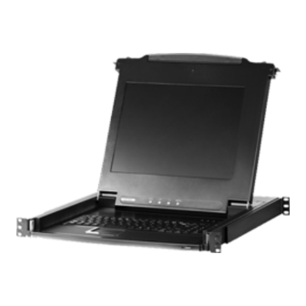
17" Setup is fast and easy. Simply use the KVM cable set supplied with this package to link the CL5200's KVM port to the console port of your KVM switch and you are ready to go. For convenience, ports to link an external keyboard, video, mouse console are also provided. -
Page 14: Features
CL5200 User Manual Features Integrated KVM console with 15"or 17" LCD monitor - in a sliding housing with top and bottom clearance for smooth operation in a 1U high system rack Standard rack mount kit included – optional Easy Rack Mounting (single... -
Page 15: Requirements
1. Introduction Requirements Switches and Computers The CL5200 supports most KVM switches that have PS/2 console port connectors. If you are unsure whether your switch is supported or not, check with your dealer. The integrated LCD monitor's maximum resolution is 1024 x 768 @75Hz (15"), or 1280 x 1024 @75Hz (17"). -
Page 16: Components
CL5200 User Manual Components Front View Component Description Handle Pull to slide the KVM module out; push to slide the module in. Slide Release In order to slide the console out, you must first release it by moving this tab sideways. See p. 11 for details on sliding the console in and out. -
Page 17: Cl5200C / Cl5200D Rear View
(see Console Selection, page 16 for details). KVM Port The cable that links the CL5200 to the KVM switch plugs in here Note: The shape of this 15-pin connector has been... -
Page 18: Cl5200L / Cl5200M Rear View
(see Console Selection, page 16 for details). KVM Port The cable that links the CL5200 to the KVM switch plugs in here Note: The shape of this 15-pin connector has been... -
Page 19: Hardware Setup
Keyboard Power On function. Standard Rack Mounting A standard rack mount kit is provided with your CL5200. The kit enables the switch to be mounted in rack with a depth of 42 - 72 cm. - Page 20 CL5200 User Manual To rack mount the switch, do the following: 1. While one person positions the switch in the rack and holds it in place, the second person - using the screws provided with the rack mount kit - loosely screws the front brackets to the rack.
-
Page 21: Installation
Console Section of the CL5200. The ports are color coded and marked with an icon for easy identification. 5. Plug the power cord into the CL5200's power socket and into a DC power source. -
Page 22: Cl5200L / Cl5200M
Console Section of the CL5200. The ports are color coded and marked with an icon for easy identification. 4. Plug the power cord into the CL5200's power socket and into an AC power source. -
Page 23: Operation
Chapter 3 Operation Opening the Console The CL5200's console is located under the top cover. To access the console, slide the console module out and raise the cover. Note: As a safety precaution, to keep the console from accidentally sliding out, the console is locked into the In position. -
Page 24: Closing The Console
CL5200 User Manual Closing the Console To slide the console module back in, close the cover and do the following: 1. Pull the safety catches on the unit's side rails toward you and push the module in until it stops. -
Page 25: Operating Precautions
3. Operation Operating Precautions The maximum load bearing capacity of the keyboard module is 30kg. Failure to heed the information below can result in damage to the keyboard module. Right! Rest your hands and arms lightly on the keyboard module as you work. Wrong! DO NOT lean your body weight on the keyboard module. -
Page 26: Lcd Osd Configuration
CL5200 User Manual LCD OSD Configuration The LCD Buttons The LCD OSD allows you to set up and configure the LCD display. Four buttons are used to perform the configuration, as described in the table, below: Button Function MENU When you have not entered the LCD OSD Menu function, pressing this button invokes the Menu function, and brings up the Main Menu. -
Page 27: The Adjustment Settings
3. Operation The Adjustment Settings An explanation of the LCD OSD adjustment settings is given in the table below: Setting Explanation Brightness Adjusts the background black level of the screen image. Contrast Adjusts the foreground white level of the screen image. Phase Adjusts the vertical size of the screen image. -
Page 28: Console Selection
3. If the KVM switch connected to the CL5200 uses the [Ctrl] [Alt] [Shift] combination to invoke its hotkey mode, you won't be able to access any of its hotkey operations because the CL5200 will capture the combination for console selection first. -
Page 29: Appendix
Appendix Optional Rack Mounting For convenience and flexibility, three optional rack mount kits are available: A long bracket standard rack mount kit for 68.0 - 100.0 cm racks; A short bracket Easy-Installation rack mount kit for 42.0 - 70.0 cm racks; A long bracket Easy-Installation rack mount kit for 68.0 - 105.0 cm racks. - Page 30 CL5200 User Manual 2. Attach the left and right easy-installation mounting rails to the inside of the rack. The flange that supports the switch will be to the inside. Rear Flange Slide Bar Sliding Attachment Bracket LEFT Support Rear Flange...
- Page 31 3. Slide the switch onto the support flanges. Use the screws supplied with this package to loosely attach the front of the switch to the front of the rack (only tighten the screws part way). Phillips I head M4 x 6 4.
- Page 32 CL5200 User Manual 5. Slide the switch open and closed a couple of times to be sure that it is properly aligned and operating smoothly. (See p. 11 for opening and closing procedures.) 6. After determining that the switch is properly lined up and operating correctly, finish up by fully tightening down the partially tightened front attachment screws inserted in step 3.
-
Page 33: Specifications
Specifications CL5200C / CL5200D Function CL5200C CL5200D Connectors KVM Ports 1 x SP HD-15 F 1 x 6 pin mini-DIN F (Purple) External Keyboard Console Ports Video 1 x HDB-15 F 1 x 6 pin mini-DIN F (Green) Mouse Switches Power 1 x Rocker LCD Adjust... -
Page 34: Cl5200L / Cl5200M
CL5200 User Manual CL5200L / CL5200M Function CL5200L CL5200M Connectors KVM Ports 1 x SP HD-15 F External Keyboard 1 x 6 pin mini-DIN F (Purple) Console Ports Video 1 x HDB-15 F Mouse 1 x 6 pin mini-DIN F (Green) -
Page 35: Troubleshooting
Replace the VGA cable with one of an appropriately short length. When I try to perform If the KVM switch connected to the CL5200 uses the hotkey operations on my [Ctrl] [Alt] [Shift] combination to invoke its hotkey mode, KVM switch, nothing you won't be able to access any of its hotkey operations. -
Page 36: Limited Warranty
CL5200 User Manual Limited Warranty IN NO EVENT SHALL THE DIRECT VENDOR'S LIABILITY EXCEED THE PRICE PAID FOR THE PRODUCT FROM THE DIRECT, INDIRECT, SPECIAL, INCIDENTAL OR CONSEQUENTIAL DAMAGES RESULTING FROM THE USE OF THE PRODUCT, DISK OR ITS DOCUMENTATION. - Page 37 Index , 16 Numbering Cables Components Rack Mounting CL-5200C/CL-5200D Rear View , 17 Optional CL-5200L/CL-5200M Rear View , vi Safety information Front View Standard , 16 Console Selection Rear View CL-5200C/CL-5200D CL-5200L/CL-5200M Features Requirements Front View Cables OS Support Switches and Computers Installation CL-5200C / CL-5200D , 10...
Need help?
Do you have a question about the CL5200 and is the answer not in the manual?
Questions and answers