Trane Tracer ZN521 Installation And Operation Manual
Zone controller
Hide thumbs
Also See for Tracer ZN521:
- Installation and operation manual (84 pages) ,
- User manual (12 pages)
Table of Contents
Advertisement
Quick Links
Installation and
Operation
™
Tracer
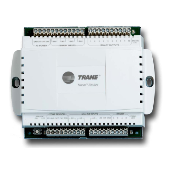
ZN521 Zone Controller
SAFETY WARNING
Only qualified personnel should install and service the equipment. The installation, starting up, and servicing
of heating, ventilating, and air-conditioning equipment can be hazardous and requires specific knowledge and
training. Improperly installed, adjusted or altered equipment by an unqualified person could result in death or
serious injury. When working on the equipment, observe all precautions in the literature and on the tags,
stickers, and labels that are attached to the equipment.
November 2010
CNT-SVX07D-EN
Advertisement
Table of Contents

Related Manuals for Trane Tracer ZN521


Summary of Contents for Trane Tracer ZN521
- Page 1 Installation and Operation ™ Tracer ZN521 Zone Controller SAFETY WARNING Only qualified personnel should install and service the equipment. The installation, starting up, and servicing of heating, ventilating, and air-conditioning equipment can be hazardous and requires specific knowledge and training. Improperly installed, adjusted or altered equipment by an unqualified person could result in death or serious injury.
- Page 2 © 2010 Trane All rights reserved This document and the information in it are the property of Trane and may not be used or reproduced in whole or in part, without the written permission of Trane. Trane reserves the right to revise this publication at any time and to make changes to its content without obligation to notify any person of such revision or change.
-
Page 3: Table Of Contents
Table of Contents Overview and specifications ..........6 Product description . - Page 4 Unoccupied mode ..........32 Occupied standby mode .
- Page 5 Status indicators for operation and communication ..... . 43 Test button ............43 Manual output test .
-
Page 6: Overview And Specifications
Note: For information about using the Rover service tool, see the current version of the Rover Installation/Operation/Programming guide (EMTX-SVX01). Storage environment If a Tracer ZN521 zone controller is to be stored for a substantial amount of time, store it in an indoor environment that meets the following requirements: •... -
Page 7: Clearances
Overview and specifications Clearances Plastic-cover model (see Figure 1 on page 7) • Front: 4.0 in. (102 mm) • Each side: 1.0 in. (25 mm) • Top and bottom: 4.0 in. (102 mm) Metal-cover model (see Figure 2 on page 8) •... -
Page 8: Agency Listing/Compliance
Use a UL-listed Class 2 power transformer supplying a nominal 24 Vac (19–30 Vac) to power both the Tracer ZN521 zone controller (14 VA) and its associated output devices, including relays and actuators, to a maximum of 12 VA per output utilized. - Page 9 Occupancy, condensate overflow, low-coil-temperature, and fan status inputs accept switching devices that may have normally open or normally closed dry contacts. Output devices Output devices connected to the Tracer ZN521 binary outputs cannot exceed 12 VA (0.5 A) current draw at 24 Vac. Zone temperature sensors...
-
Page 10: General Wiring Information
Important: Do not share 24 Vac between controllers. All wiring must comply with National Electrical Code and local codes. The ac power connections are in the top left corner of the Tracer ZN521 zone controller (see Figure CNT-SVX07D-EN... -
Page 11: Communication-Link Wiring And Addressing
24 Vac transformer The Tracer ZN521 may be powered by an existing transformer integral to the controlled equipment, provided the transformer has adequate power available and proper grounding is observed. If you are providing a new transformer for power, use a UL-listed Class 2 power transformer supplying a nominal 24 Vac (19–30 Vac). -
Page 12: Mounting The Controller
Mounting recommendations are as follows: Notice: Leave Controller Cover On Mount the Tracer ZN521 zone controller with the cover on to avoid the possibility of damaging the circuit board during installation. • Mount the controller in any position, other than with the front of the cover facing downward. -
Page 13: Input/Output Functions And Wiring For Typical Applications
Input/output functions and wiring for typical applications This chapter provides information about the function of inputs and outputs and examples of wiring for typical applications. Applications supported by the Tracer ZN521 zone controller are shown in Table Table 2. Typical applications for the Tracer ZN521 zone controller... -
Page 14: Bi1: Low-Coil-Temperature Detection
The function of condensate overflow is to prevent the condensate drain pan from overflowing and causing water damage to the building. If BI2 is wired to a condensate overflow switch and the level of condensate reaches the trip point, the Tracer ZN521 will detect the condition and generate a Condensate Overflow diagnostic. -
Page 15: Gnd: Ground Terminals
The ZN analog input functions as the local (hard-wired) zone temperature input. The controller receives the temperature as a resistance signal from a 10 kΩ thermistor in a standard Trane zone sensor wired to analog input ZN. A zone temperature value communicated by means of a LonTalk link can also be used for controllers operating on a BAS. -
Page 16: Ai1: Entering Water Temperature
Economizing (free cooling) is a function whereby outdoor air is used as a source of cooling before hydronic or DX cooling is used. The Tracer ZN521 uses the outdoor air temperature value to determine whether economizing is feasible. Economizing is not possible without a valid outdoor air temperature. -
Page 17: Ai4: Universal 4-20 Ma
Figure 5. The sensor will transmit a 0–2000 ppm value to the BAS. This configuration has no direct effect on Tracer ZN521 operation. If a valid value is established and then is no longer present, the controller generates a CO Sensor Failure diagnostic. -
Page 18: Binary Outputs
Tri-state modulating outdoor/return air damper • Tri-state modulating face-and-bypass damper The Tracer ZN521 controller includes ten binary outputs. Each binary output is a triac with a rating of 12 VA at 24 Vac. Table 6 describes the function of each output. -
Page 19: Generic Binary Output
“Manual output test, ” p. The water valve override feature is a procedure used for water balancing. Using the Rover service tool or a BAS, a user can specify that a Tracer ZN521 override the state of water valves to: •... - Page 20 Input/output functions and wiring for typical applications Figure 7. Two-pipe hydronic-cooling unit † 24 V Fan, high speed † 24 V Exhaust (or fan, medium speed) † 24 V Fan, low speed Fan status (closed=on)* † 24 V Cooling valve Occupancy (open=occupied)* †...
- Page 21 Input/output functions and wiring for typical applications Figure 8. Two-pipe hydronic-heating unit † 24 V Fan, high speed † 24 V Exhaust (or fan, medium speed) † 24 V Fan, low speed Fan status (closed=on)* † 24 V Occupancy (open=occupied)* Heating valve Condensate overflow (closed=normal)* †...
- Page 22 Input/output functions and wiring for typical applications Figure 9. Two-pipe hydronic heating/cooling unit with auto changeover † 24 V Fan, high speed † 24 V Exhaust (or fan, medium speed) † 24 V Fan, low speed † Fan status (closed=on) 24 V Heating/cooling changeover valve Occupancy (open=occupied)*...
- Page 23 Input/output functions and wiring for typical applications Figure 10. Four-pipe hydronic heating/cooling unit † 24 V Fan, high speed † 24 V Exhaust (or fan, medium speed) † 24 V Fan, low speed Fan status (closed=on)* † 24 V Occupancy (open=occupied)* Cooling valve †...
- Page 24 Input/output functions and wiring for typical applications Figure 11. Four-pipe heating/cooling unit with auto changeover † 24 V Fan, high speed † 24 V Exhaust (or fan, medium speed) † 24 V Fan, low speed Fan status (closed=on)* † 24 V Occupancy (open=occupied)* Heating/cooling changeover valve †...
- Page 25 Input/output functions and wiring for typical applications Figure 12. Two-pipe heating unit with DX cooling † 24 V Fan, high speed † 24 V Exhaust (or fan, medium speed) † 24 V Fan, low speed Fan status (closed=on)* † 24 V DX cooling Occupancy (open=occupied)* †...
- Page 26 Input/output functions and wiring for typical applications Figure 13. Electric heat unit with DX cooling † 24 V Fan, high speed † 24 V Exhaust Fan status (closed=on)* † 24 V DX cooling Occupancy (open=occupied)* † 24 V Electric heat, stage 1 (optional) †...
- Page 27 Input/output functions and wiring for typical applications Figure 14. Electric heat unit † 24 V Fan, high speed † 24 V Exhaust Fan status (closed=on)* Occupancy (open=occupied)* † 24 V Electric heat, stage 1 † 24 V Condensate overflow (closed=normal)* Electric heat, stage 2 †...
- Page 28 Input/output functions and wiring for typical applications Figure 15. Two-pipe heating unit with face-and-bypass damper † 24 V Fan, high speed † 24 V Exhaust (or fan, medium speed) † 24 V Fan, low speed Fan status (closed=on)* † 24 V Face &...
- Page 29 Input/output functions and wiring for typical applications Figure 16. Two-pipe heating/cooling unit with face-and-bypass damper † 24 V Fan, high speed † 24 V Exhaust (or fan, medium speed) † 24 V Fan status (closed=on)* Fan, low speed † 24 V Occupancy (open=occupied)* Heating/cooling isolation valve, open/close †...
- Page 30 Input/output functions and wiring for typical applications Figure 17. Four-pipe heating/cooling unit with face-and-bypass damper † † 24 V 24 V Fan, high speed Exhaust (or fan, medium speed) † 24 V Fan, low speed † 24 V Fan status (closed=on)* Cooling isolation valve, open/close †...
-
Page 31: Sequence Of Operations
Power-up sequence When 24 Vac power is initially applied to the Tracer ZN521 zone controller, the following sequence occurs: 1. The green status indicator LED turns on (see “Interpreting LEDs, ”... -
Page 32: Occupied Mode
The occupied bypass time, which resides in the Tracer ZN521 and defines the duration of the override, is configurable from 0 to 240 minutes (default value of 120 minutes). When the occupied bypass time expires, the unit transitions from occupied bypass mode to unoccupied mode. -
Page 33: Zone Temperature Control
Trane zone sensor or the occupied bypass time expires. Zone temperature control The Tracer ZN521 zone controller uses two methods of zone temperature control: • Cascade zone control—used in the occupied, occupied bypass, and occupied standby modes •... -
Page 34: Morning Warm-Up
Sequence of operations position, causing the discharge air temperature to fall below the Discharge Air Control Point Low Limit. Morning warm-up Morning warm-up can occur any time the controller is in the occupied mode. The controller supply fan always runs in the occupied mode. Morning warm-up is initiated when the zone temperature is more than 2°F (1.1°C) below the occupied heating setpoint. -
Page 35: Entering Water Temperature Sampling Function
Fan operation The Tracer ZN521 supports up to three fan speeds. Every time the fan is enabled, the fan will begin operation and run on high speed for a period of time (0.5 seconds for fan coils and 3 seconds for unit ventilators and blower coils) before changing to any other speed. -
Page 36: Valve Operation
(135% of the stroke time) whenever a position of 0% or 100% is requested. as part of Tracer ZN521 normal operation. At power-up or after a power outage, the controller first drives all modulating valves (and dampers) to the closed position. The controller calibrates to the fully closed position by overdriving the actuator (135% of the stroke time). -
Page 37: Two-Pipe Operation
Sequence of operations Two-pipe operation For two-pipe applications, the Tracer ZN521 can be configured as heating only, cooling only, or heat/cool changeover. The coil can be used as the primary heating source and/or the primary cooling source. If present, an electric heating element can be used only as the primary heating source (instead of hydronic or steam heating). -
Page 38: Ashrae Cycle 1 Conformance
The modulating outdoor air damper provides the first source of cooling for the Tracer ZN521. The controller initiates economizing if the outdoor air temperature is below the economizer enable point (configurable using the Rover service tool). If economizing is initiated, the controller modulates the outdoor air damper (between the active minimum damper position and 100%) to control the amount of outdoor air cooling capacity. -
Page 39: Two-Position Control Of A Modulating Outdoor Air Damper
(typically, 100%). Face-and-bypass damper operation The Tracer ZN521 can control a face-and-bypass damper to modulate a percentage of air to the face of the coil(s) and around (bypass) the coil(s) to maintain zone comfort. For two-pipe changeover applications, if the controller requests heating and hot water is available, the face-and-bypass damper modulates to the face position. -
Page 40: Dehumidification
Dehumidification disables the economizing function. Peer-to-peer communication Tracer ZN521 zone controllers have the ability to share data with other LonTalk-based controllers. Multiple controllers can be bound as peers, using the Rover service tool, to share: •... -
Page 41: Smart Reset
Sequence of operations Smart reset The Tracer ZN521 will automatically restart a unit that is locked-out as a result of a Low Coil Temp Detection (BI1) diagnostic. Referred to as “smart reset, ” this automatic restart will occur 30 minutes after the diagnostic occurs. -
Page 42: Freeze Protection (Discharge Air Temperature Low Limit)
Sequence of operations • Valves are driven open to allow water to flow through the coil • Fan is off • Face-and-bypass damper (when present) is at full bypass • Economizing is disabled • The outdoor/return air damper is closed •... -
Page 43: Status Indicators For Operation And Communication
Status indicators for operation and communication This chapter describes the operation and communication status indicators on the Tracer ZN521 controller, including: • A description of the location and function of the Test button and Service pin button and the light- emitting diodes (LEDs) located on the controller •... - Page 44 Status indicators for operation and communication The procedure is as follows: 1. Press and hold the Test button for 3 to 4 seconds, then release it to start the test mode. The green (status) LED goes off when you press the Test button, and then it blinks (as described in Table 14 on page 47) when the Test button is released to indicate that the controller is in manual test mode.
- Page 45 Table 11. Manual output test sequence for non-face-and-bypass configurations Step Result BOP1 BOP2 BOP3 BOP4 BOP5 BOP6 BOP7 BOP8 BOP9 BOP10 Begins test On/Close 1) On/Close On/Close mode 2) Off Fan high On/High 1) On/Med medium 2) Off Fan low On/Low Main open, On/High...
- Page 46 Table 12. Manual output test sequence for face-and-bypass configurations (two-position isolation valves only) Step Result BOP1 BOP2 BOP3 BOP4 BOP5 BOP6 BOP7 BOP8 BOP9 BOP10 Begins test On/Close On/Close mode Fan high On/High On/Open 1) On/Med On/Open medium 2) Off Fan low On/Low On/Open...
-
Page 47: Service Pin Button
(see Table 14 on page 47 and “Setting the Auto-wink option” in EMTX-SVX01A-EN) Interpreting LEDs The red (service) LED on the Tracer ZN521 controller (see Figure 19 on page 43) indicates whether the controller is capable of operating normally (see Table 13). -
Page 48: Diagnostics
Status indicators for operation and communication The yellow (communications) LED on the Tracer ZN521 controller (see Figure 19 on page 43) indicate the controller’s communication status (see Table 15). Table 15. Yellow LED: Communications indicator LED activity Explanation LED is off continuously... -
Page 49: Table Of Diagnostics
“Manual (latching) diagnostics. ” Table of diagnostics Table 16 presents each diagnostic that can be generated by the Tracer ZN521, its effect on outputs (consequences), and its type. Note: The generic binary output is unaffected by diagnostics. Table 16. Diagnostics... - Page 50 Status indicators for operation and communication Table 16. Diagnostics (continued) Diagnostic Diagnostic Probable cause Consequences type Discharge Air Temp Failure Invalid or missing value for Fan off Automatic discharge air temperature Valves closed Outdoor air damper closed Face and bypass damper bypass DX cooling/electric heat off Baseboard heat off Outdoor Air Temp Failure...
-
Page 51: Troubleshooting
No power to the con- If the controller does not have power, the unit fan does not operate. For the Tracer ZN521 troller controller to operate normally, it must have an input voltage of 24 Vac. If the green LED is off continuously, the controller does not have sufficient power or has failed. - Page 52 Troubleshooting Table 18. Valves remain closed Probable cause Explanation Unit wiring The wiring between the controller outputs and the valve(s) must be present and correct for normal valve operation. Refer to applicable wiring diagram. Failed end device The valves must be checked to ensure proper operation. No power to the con- If the controller does not have power, the unit valve(s) will not operate.
- Page 53 No power to the If the controller does not have power, heat outputs do not operate. For the Tracer ZN521 controller controller to operate normally, you must apply an input voltage of 24 Vac. If the green LED is off continuously, the controller does not have sufficient power or has failed.
- Page 54 If the controller does not have power, the outdoor air damper does not operate. For the controller Tracer ZN521 controller to operate normally, you must apply an input voltage of 24 Vac. If the green LED is off continuously, the controller does not have sufficient power or has failed.
-
Page 55: Index
Index Numerics BI3 configuration options 14 Tri-state modulating 6 BI4 (Fan status) 14 Two-position control 39 24 Vac wiring 10 Switching devices 9 Data sharing 40 – Binary outputs 18 Dehumidification 40 AC-power wiring 10 Generic 19 Device addressing for BAS communication 11 Actuators Manual output test 43... - Page 56 Index – Electric heat Input/output functions 13 Switching devices 9 Operation 39 Input/output terminal wiring 10 Occupancy input 14 Supported application 18 Invalid unit configuration Occupancy modes 31 diagnostic 50 Troubleshooting 53 General 31 Isolation valve operation 39 Entering water temperature Occupied 32 Diagnostic 49 Occupied bypass 32...
- Page 57 Index ASHRAE Cycle 1 38 Storage environment 6 Fan status 41 ASHRAE Cycle 2 38 Transformers 11 Filter-maintenance timer 41 Baseboard heat 39 Status indicators for operation and Freeze avoidance 41 communication Dehumidification 40 Freeze protection 42 Diagnostics 48 Discharge air temperature low Low-coil-temperature limit 42 General 43...
- Page 58 Index Two-pipe hydronic heating/ cooling unit with auto changeover 22 Two-pipe hydronic-cooling unit 20 Two-pipe hydronic-heating unit 21 Zone humidity Sensor 9 Zone temperature Input 15 Sensors 9 Zone temperature control 33 Zone temperature failure diagnostic 49 CNT-SVX07D-EN...
- Page 60 HVAC systems, comprehensive building services, and parts. For more information, visit www.Trane.com. Trane has a policy of continuous product and product data improvement and reserves the right to change design and specifications without notice. © 2010 Trane All rights reserved...
Need help?
Do you have a question about the Tracer ZN521 and is the answer not in the manual?
Questions and answers