
Related Manuals for Trane ZN. LonWorks control


Summary of Contents for Trane ZN. LonWorks control
- Page 1 Installation - Operation - Maintenance and user guide Trane ZN. LonWorks ® control for fan coil units and chilled water cassettes (CWS) CNT-SVX13B-E4...
-
Page 2: General Information
About this manual These instructions are given as a guide to good practice in the installation, start-up, operation and periodic maintenance by the user of Trane ZN. LonWorks control. They ® do not contain the full service procedures necessary for the continued successful operation of this equipment. -
Page 3: Table Of Contents
Contents General information Description Features Occupancy modes Setpoint operation Automatic Heat/cool mode determination Sequence of operation Control features Binary inputs Communication Zone sensor option Zone sensor technical features Default values Data lists Modulating valve package Valve bodies Installation Unit identification Neuron identification Electrical connection Connecting the zone sensors... -
Page 4: Description
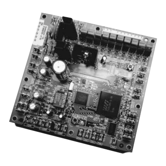
Description The Tracer ® ZN. unit controller is a microprocessor-based direct digital controller that is dedicated to the control and the optimization of chilled water terminal units. The unit controller is designed to provide improved comfort with a minimum energy consumption through the use of custom proportional integral derivative (PID) control algorithms as well as intelligent fan speed and... -
Page 5: Features
Features The ZN. unit controller may be • Unoccupied (or Antifreeze): Normal applied as part of a Trane Tracer operating mode for unoccupied Summit™ system, as a stand-alone spaces or nighttime operation. device, or as an interoperable Unoccupied cooling and heating controller. -
Page 6: Setpoint Operation
Features Table 1 describes the combination of communication requests, the hardwire input and the 'ON' (occupied)/'CANCEL' (unoccupied) push buttons on the zone sensor upon the occupancy state of the control. Table 1 Description Communicated Binary On/Cancel Effective occupancy request input pushbuttons mode Stand alone... -
Page 7: Automatic Heat/Cool Mode Determination
Features Figure 1 Occupied Occupied heating stp cooling stp Occupied Occupied Unoccupied standby Dead standby Unoccupied heating stp heating stp zone cooling stp cooling stp Local setpoint Typically, the range of the local Sequence of operation setpoint is from 10°C to 29°C. The Off: Fan is off, valves are closed. - Page 8 Features Figure 2 - Example: 2-pipe cooling / 2-pipe heating / 2-pipe changeover / 4-pipe operation Hs = Heating setpoint (occupied) Cs = Cooling setpoint (occupied) Db = Dead band 1. Heating valve 2. Valve position 3. 100% Open 4. Cooling 5.
-
Page 9: Control Features
• For controllers that receive a when it reaches zero, can initiate an communicated occupancy request (typically from a building alarm notification to Trane Tracer Summit™ system. The filter automation system such as Tracer maintenance status is based on Summit™): Refer to Table 1 to see the effect of cumulative fan run hours. -
Page 10: Communication
The ZN is used with the unit (not supplied by controllers are linked directly via a Trane), it is possible to connect the twisted shielded pair cable to the condensate overflow switch to the Tracer Summit™ building control controller through this binary input. - Page 11 National • Use a daisy chain configuration. Electrical Manufacturers Association See Figure 4. Trane strongly (NEMA) differs from the Category 4 recommends using a daisy chain specification proposed by the topology. Other topologies (branch, Electronic Industries Association / star…) are much less reliable.
- Page 12 Features Specifications apply to shield or unshielded 22AWG (0.65mm ) cable D-C resistance (ohms/1000 feet at 20°C) maximum for a single copper conductor regardless of whether it is solid or stranded and is or is not metal coated 18.0 D-C resistance unbalance (percent) maximum Mutual capacitance of a pair (pF/foot) maximum Pair to ground capacitance unbalance (pF/1000 feet) maximum...
- Page 13 Features Figure 5 - Simple data sharing application S = Zone sensor M = Master S = Slave LON COMM BUS = LON communication STP = Setpoint !1= Maximum 1400 m with the use of 1 repeater !2= Maximum 60 devices (120 with 1 repeater) Fan mode LON COMM BUS...
- Page 14 Features Figure 6 - More complex data sharing application Tracer Summit™ S-A1 S-A2 S-B1 ZS = Zone sensor MA = Master zone A MB = Master zone B S-Ax = Slave x zone A S-Bx = Slave x zone B ZA = Zone A ZB = Zone B !1= Maximum 1400 m with the use...
-
Page 15: Zone Sensor Option
Features Zone sensor option Two zone sensors can be connected to the ZN. control : • A simplified option zone sensor - TH02 • A full option zone sensor - TH01 Figure 7 - Simplified option zone sensor - TH02 Ref 35168531-001 ➊... - Page 16 Features Figure 8 - Full option zone sensor - TH01 Ref 35168530-001 ➊ External adjustable thumbwheel (setpoint) ➋ Occupied mode / Timed override button ➌ Unoccupied mode / Cancel override button ➍ High/Medium/Low/Auto/Off fan speed switch ➎ Built-in air temperature sensor ➏...
-
Page 17: Zone Sensor Technical Features
Features Zone sensor technical features Color of the wall sensor: light grey pantone #2C (equivalent to RAL 9002) Room temperature sensor: 10 kohms at 25°C +/- 0.2°C Thumbwheel : 1 kohms +/- 10% Working temperature: -18°C to 65°C Figures 9 and 10 show the wiring of the zone sensors. Figure 9 - Zone sensor only Figure 10 - Zone sensor + return air sensor... -
Page 18: Default Values
Features Table 2 - Recommended cables Description Cable Maximum length Polarity Wiring on terminals Occupancy 1 pair 0.9mm² 30 m J2-5 & J2-6 on printed board (B1 3) Condensate overflow 1 pair 0.9mm² 30 m J2_3 & J2_4 on printed board (BI 2) Zone sensor 2 pairs* 0.9mm²... -
Page 19: Data Lists
Features Data lists Tables 3 and 4 provide the input/output listing and the configuration properties for the unit controller. The content of the lists conforms to both the LonMark ® Space Comfort Controller Functional Profile 85.00 and the LonMark ® node object. -
Page 20: Modulating Valve Package
Features Modulating valve package The control valve is modulating depending on the 24V triac signal from the controller, which determines the valve position by a control algorithm. If the valve loses power, the valve returns to the close position. Valve packages are factory- mounted and leak-tested at 13 bar. - Page 21 Features 3-way/4-port modulating valves (V5833C) Action Normally Closed (NC) Water temperature 2-120°C Maximum stroke 6.5 mm Flow characteristic Equal percentage Port connection type Flat sealing Static pressure PN16 Leakage rate 0.02% of kvs Suitable medium Water, with maximum 50% glycol UniTrane #01-08 HFO/HFR 04-06-08"...
- Page 22 Features CNT-SVX13B-E4...
-
Page 23: Installation
Installation Unit identification Units arrive on site with an identification sticker with pictograms, which clearly indicates important information such as the customer order number, job name, unit model size, coil type, presence of an electric heater, motor type, unit handing, and so on. Figure 11: Unit identification sticker (UniTrane, HFO/HFR only) CNT-SVX13B-E4... - Page 24 Installation = Indicates unit description = Indicates the ZN control configuration program 2-pipe cooling only 2-pipe heating only 2-pipe cooling + electric heater 2-pipe changeover, 2-way valve 2-pipe changeover, 3-way valve 2-pipe changeover + electric heater, 2-way valve 2-pipe changeover + electric heater, 3-way valve 4-pipe = Indicates customer order number = Indicates the coil type...
-
Page 25: Neuron Identification
Installation Installation Control Panel Kit Identification (CWS) For all chilled water cassettes, the ZN LonTalk® control is available as a kit. • 5 valve packages are available depending on the unit size and the operating (cooling or heating) mode. • 6 control panel kits are available depending on the application: 2-pipe cooling only 2-pipe heating only... -
Page 26: Electrical Connection
Fan coils electrical control box. subordinated to operation of the fan. manufactured by Trane comply with Warning: Disconnect the power CEI regulations. The changeover supply before making electrical sensor must be installed on the connections. -
Page 27: Communication Between Units
Installation Figure 15 A = TH01 only 1 = Field-supplied contact - - - - - Customer wiring Recommended cable size: 2 pairs 0.9mm², maximum 60m If TH01 + 1 pair 0.9mm², capacitance 72±6pf/m max, maximum 60m. Communication between units It is possible to connect several units together thanks to a communication bus. -
Page 28: Main Power Supply
Installation Main power supply Units with modulating/communicating control are supplied with the fuse disconnect switch. Refer to the wiring diagrams supplied with the units for more information. To connect main power supply, refer to Figures 17 to 19. Figure 17 - UniTrane, HFO/HFR without Figure 19 - Power-supply for CWS units electric heater Figure 18 - UniTrane, HFO/HFR with... -
Page 29: Troubleshooting
Troubleshooting LED operation Red service LED Table 5 - Red service LED activity Red LED activity Description LED is off continuously after power is Normal operation applied to the controller LED is on continously, even when power Someone is pressing the Service push is first applied to the controller button or the controller has failed LED flashes about once every second... -
Page 30: Manual Output Test
Troubleshooting Yellow comm LED The yellow LED does not blink when The yellow comm LED blinks at the the controller is transmitting rate the controller receives communication data. Table 7 communication. describes the different patterns. Table 7 - Yellow Comm LED activity Yellow LED activity Description LED off continuously... -
Page 31: Questionable Unit Operation
However, based on the current step in the test sequence, the unit fan may not be on. Fan mode off When a local fan mode switch (provided on the Trane zone sensor) determines the fan operation, the off position controls the unit off. Requested mode off You can communicate a desired operating mode (such as off, heat, and cool) to the controller. - Page 32 Troubleshooting Table 10 - Valves stay open Probable cause Explanation Unit wiring The wiring between the controller outputs and the valve(s) must be present and correct for normal valve operation. Unit configuration The controller must be properly configured based on the actual installed end devices and application.
-
Page 33: User Guide
2 = Temperature setting 3 = Occupied mode / Timed Override 4 = Unoccupied mode / Cancel Override TH01: Trane reference 35168530-001 TH02: Trane reference 35168531-001 Note:To avoid accidental engaging of a mode, push buttons 'On' and 'Cancel' must be held in for at least 1 second. - Page 34 Notes CNT-SVX13B-E4...
- Page 35 Notes CNT-SVX13B-E4...
- Page 36 For more information contact your local district Société Trane – Société Anonyme au capital de 61 005 000 Euros – Siege Social: 1 rue des Amériques – 88190 office or e-mail us at comfort@trane.com Golbey –...
Need help?
Do you have a question about the ZN. LonWorks control and is the answer not in the manual?
Questions and answers