Sign In
Upload
Manuals
Brands
Trane Manuals
Controller
Tracer ZN517
Trane Tracer ZN517 Manuals
Manuals and User Guides for Trane Tracer ZN517. We have
1
Trane Tracer ZN517 manual available for free PDF download: Installation And Operation Manual
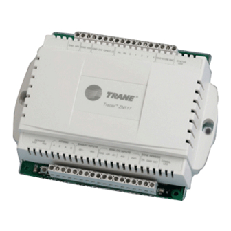
Trane Tracer ZN517 Installation And Operation Manual (111 pages)
Unitary Controller
Brand:
Trane
| Category:
Controller
| Size: 1.99 MB
Table of Contents
Table of Contents
7
Chapter 1 Overview and Specifications
13
Product Description
13
Dimensions
13
Clearances
14
Power
14
Operating Environment
14
Storage Environment
16
Agency Listing/Compliance
16
Factory Default Temperature Setpoints
16
Additional Components
18
Power Transformer
18
Zone Temperature Sensors
18
Discharge Air Temperature Sensors
18
Damper Actuators (Optional)
18
Chapter 2 Mounting the Controller
19
Location Recommendations
19
Mounting Recommendations
20
Chapter 3 Applications for the 2-Heat/2-Cool Configuration
21
Wiring Requirements and Options
22
DIP Switch Settings
24
Binary Outputs for 2-Heat/2-Cool Applications
25
Binary Output 5
25
Overriding Binary Outputs
26
Binary Inputs for 2-Heat/2-Cool Applications
26
BI1: Occupancy or Generic
26
BI2: Fan Status
26
Analog Inputs for 2-Heat/2-Cool Applications
27
AI1: Universal 4-20 Ma
27
AI2: Outdoor Air Temperature or Generic Temperature
29
DAT: Discharge Air Temperature
29
ZN: Zone Temperature
30
SET: Temperature Setpoint
30
Chapter 4 Sequence of Operations for the 2-Heat/2-Cool
31
Configuration
31
Power-Up Sequence
31
Cascade Zone Control
32
Simplified Zone Control
32
Occupancy Modes
32
Occupied Mode
33
Unoccupied Mode
33
Occupied Standby Mode
33
Occupied Bypass Mode
34
Timed Override Control
34
Outdoor Air Damper Operation
34
Fan Operation
35
Peer-To-Peer Communication
35
Economizing
35
Discharge Air Tempering
36
Demand Control Ventilation
36
Unit Protection Strategies
36
Filter-Maintenance Timer
37
Fan off Delay
37
Fan Status
37
Chapter 5 Applications for the 4-Cool Configuration
39
Wiring Requirements and Options
40
DIP Switch Settings
42
Binary Outputs for 4-Cool Applications
43
Binary Output 5
43
Overriding Binary Outputs
43
Binary Inputs for 4-Cool Applications
44
BI1: Occupancy or Generic
44
BI2: Fan Status
44
Analog Inputs for 4-Cool Applications
45
AI1: Universal 4-20 Ma
45
AI2: Outdoor Air Temperature or Generic Temperature
47
DAT: Discharge Air Temperature
47
ZN: Zone Temperature
48
SET: Temperature Setpoint
48
Chapter 6 Sequence of Operations for the 4-Cool
49
Configuration
49
Power-Up Sequence
49
Cascade Zone Control
50
Simplified Zone Control
50
Occupancy Modes
50
Occupied Mode
51
Unoccupied Mode
51
Occupied Standby Mode
51
Occupied Bypass Mode
52
Timed Override Control
52
Outdoor Air Damper Operation
52
Fan Operation
53
Peer-To-Peer Communication
53
Economizing
53
Discharge Air Tempering
54
Demand Control Ventilation
54
Unit Protection Strategies
54
Filter-Maintenance Timer
55
Fan off Delay
55
Fan Status
55
Chapter 7 Applications for the Heat Pump Configuration
57
Wiring Requirements and Options
58
DIP Switch Settings
60
Binary Outputs for Heat Pump Applications
61
Binary Output 5
61
Overriding Binary Outputs
61
Binary Inputs for Heat Pump Applications
62
BI1: Occupancy or Generic
62
BI2: Fan Status
62
Analog Inputs for Heat Pump Applications
63
AI1: Universal 4-20 Ma
63
AI2: Outdoor Air Temperature or Generic Temperature
65
DAT: Discharge Air Temperature
65
ZN: Zone Temperature
66
SET: Temperature Setpoint
66
Chapter 8 Sequence of Operations for the Heat Pump
67
Configuration
67
Power-Up Sequence
67
Cascade Zone Control
68
Simplified Zone Control
68
Occupancy Modes
68
Occupied Mode
69
Unoccupied Mode
69
Occupied Standby Mode
69
Occupied Bypass Mode
70
Timed Override Control
70
Outdoor Air Damper Operation
70
Heating or Cooling Mode
71
Fan Operation
71
Compressor Operation
71
Reversing Valve Operation
71
Economizing
72
Discharge Air Tempering
72
Demand Control Ventilation
72
Peer-To-Peer Communication
73
Unit Protection Strategies
73
Filter-Maintenance Timer
73
Fan off Delay
74
Fan Status
74
Chapter 9 PID Control
75
What PID Loops Do
75
PID Calculations
76
Proportional Calculation
76
Integral Calculation
76
Derivative Calculation
77
Sampling Frequency
77
PID Loop Action
80
Direct Action
80
Reverse Action
80
Error Deadband
81
Adjusting Error Deadband for Modulating Outputs
81
Adjusting Error Deadband for Staged Outputs
81
Other PID Settings
83
Troubleshooting Procedure
83
Tips for Specific Problems
84
Changing the Sampling Frequency
84
Changing the Gains
84
Chapter 10 Status Indicators for Operation and Communication
85
Test Button
85
Manual Output Test
86
Service Pin Button
86
Interpreting Leds
88
Diagnostics
90
Diagnostic Types
90
Table of Diagnostics
91
Chapter 11 General Wiring Information
93
Input/Output Terminal Wiring
93
Wiring Specifications
93
HVAC Unit Electrical Circuit Wiring
94
Chapter 11 General Wiring Information
96
AC Power Wiring
97
Communication-Link Wiring and Addressing
98
Chapter 12 Troubleshooting
99
Initial Troubleshooting
100
Diagnosing Operational Problems
100
Index
105
Advertisement
Advertisement
Related Products
Trane Tracer ZN.520
Trane Tracer ZN524
Trane Tracer ZN521
Trane Tracer ZN511
Trane Tracer ZN510
Trane ZN. LonWorks control
Trane TRACER CH532
Trane Tracer VV550
Trane Tracer VV551
Trane Tracer AH540
Trane Categories
Air Conditioner
Heat Pump
Chiller
Air Handlers
Furnace
More Trane Manuals
Login
Sign In
OR
Sign in with Facebook
Sign in with Google
Upload manual
Upload from disk
Upload from URL