Table of Contents
Advertisement
Quick Links
© 2011, Moog Videolarm, Inc. All Rights Reserved
B M T 1 0
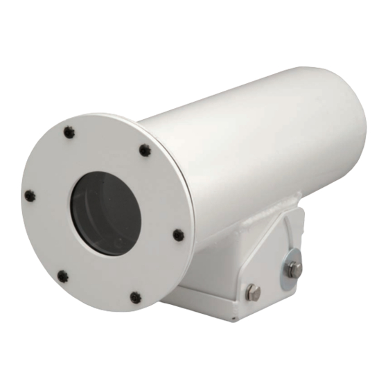
Outdoor Camera Housings
Installation and Operation Instructions for the following models:
BMT10C
Steel Bullet-Resistant Outdoor housing with Window Guard™ paint shield, plus
115Vac heater/thermostat (Level III). Tough enough to stop a .44 Magnum bullet
BMT10C2
Steel Bullet-Resistant Outdoor housing with Window Guard™ paint shield, plus 24Vac
heater/thermostat. Tough enough to stop a .44 Magnum bullet
BMT10C3
Steel Bullet-Resistant Outdoor housing with Window Guard™ paint shield, plus
220/240Vac heater/thermostat. Tough enough to stop a .44 Magnum bullet
Before attempting to connect or operate this product, please read these instructions completely.
www.videolarm.com
81-IN5192
12-21-2011
Advertisement
Table of Contents

Subscribe to Our Youtube Channel
Related Manuals for Moog Videolarm BMT10 SERIES


Summary of Contents for Moog Videolarm BMT10 SERIES
- Page 1 © 2011, Moog Videolarm, Inc. All Rights Reserved B M T 1 0 Outdoor Camera Housings www.videolarm.com Installation and Operation Instructions for the following models: BMT10C Steel Bullet-Resistant Outdoor housing with Window Guard™ paint shield, plus 115Vac heater/thermostat (Level III). Tough enough to stop a .44 Magnum bullet BMT10C2 Steel Bullet-Resistant Outdoor housing with Window Guard™ paint shield, plus 24Vac heater/thermostat. Tough enough to stop a .44 Magnum bullet BMT10C3 Steel Bullet-Resistant Outdoor housing with Window Guard™ paint shield, plus...
-
Page 2: Important Safeguards
IMPORTANT SAFEGUARDS SAFETY PRECAUTIONS Read these instructions. Keep these instructions. CAUTION Heed all warnings RISK OF ELECTRIC SHOCK DO NOT OPEN Follow all instructions. Do not use this apparatus near water. CAUTION: TO REDUCE THE RISK OF Clean only with damp cloth. ELECTRIC SHOCK, DO NOT REMOVE COVER ( OR BACK). -
Page 3: Product Category
If Purchaser believes that the Product is defective in material or workmanship, then written notice with an explanation of the claim shall be given promptly by Purchaser to Moog Videolarm. All claims for warranty service must be made within the warranty period. -
Page 4: Standard Installation Procedure
STANDARD INSTALLATION PROCEDURE RUCTIONS 1. Carefully remove the housing from its box. 7. Remove the tilt bracket from the housing by removing the (4) hex head 2. Prepare the installation site and father the needed tools and equipment. bolts that hold the mounting base to the housing (figure 5). 3. Remove the (6) tamper resistant screws on the front of the housing with the security tool provided in the installation packet (Figure 1). Figure 5 Figure 1 8. The cable strain reliefs that are provided in the kit can now be screwed into the bottom of the housing (Figure 6). 4. Remove the front end cap from the housing (Figure 2). Figure 6 Camera 9. With appropriate hardware (not provided), attach the mounting bracket to the Adjustment Screw housing’s mounting surface (Figure 7). Figure 2 5. Loosen the camera adjustment screw (Figure 3). Figure 7 Camera 10. Run all of the incoming wiring through the ¾” threaded coupling located Adjustment Screw on the backside of the tilt bracket. You may also run the wiring through Figure 3 the bottom of the tilt bracket. Should you choose this option, plug the pipe coupling with a ¾” pipe plug, available at plumbing or hardware stores. 11. Run the incoming power wires through one of the strains reliefs, and the 6. The camera sled should now slide out of the housing (Figure 4). -
Page 5: Wall Mount Instructions
The (2) bolts with the large washers should be installed on the side with the angles slot. Tilt the housing to the desired angle and tighten all (4) of the tilt bracket hex head bolts. 12. Attach your camera to the camera sled with the provided ¼”-20 screw (Figure 9). Adjust the camera so that the front of the lens is even with the front tab of the camera sled. Figure 9 Figure 13 13. Connect the incoming power wires to the housing PC board. Connect the Reattach the front end plate with the (6) tamper resistant screws and the video cable directly to the camera, and run a set of power wires from the security tool provided. Make sure that the window and window plate housing PC board to the camera (Figure 10). do not touch the camera sled bracket. WALL MOUNT INSTRUCTIONS: ACHPCB115R2 VIDEOLARM INC. RNN 08/05 1 HTR AC_IN AC_OUT Remove the access cover by loosening the (2) security screws at the front... -
Page 6: Parts List
4. Complete steps 1-8 of the BMT10 instructions. Attach the BMT10 tilt 3. Fasten the (2) mounting straps securely around the housing using a bracket to the wall mount by using the (2) ” hex head bolts and flat-head screwdriver (Figure 22). washers provided with the wall mount. The wall mount has (4) threaded inserts for the hex head bolts attached. By alternating the pattern of the (2) bolts you can achieve any pan angle you wish (Figure 17 and 18). Figure 22 Figure 17 Figure 18 PARTS LIST: 5. After achieving the desired pan angle, tighten down the (2) ” hex head bolts. Complete steps 11-16 of the BMT10 installation instructions. 6. The wall mount packet assembly includes a ¾” pipe plug. Thread this plug into the pipe coupling at the back of the tilt bracket. 7. After the housing is installed the wall mount access cover can be reinstalled (Figure 19). Figure 19 To install the optional VLAY10 sunshield 1. Insert the (2) mounting straps through the slots in the brackets inside the sunshield (Figure 20). Part Number Description Qty. 90-BTSEC06 10-32X 5/8” BT HD SEC SCREW SS 92-WSTH04 #10 EXT TOOTH STAR L/W SS 30-VL1437 FRONT END PLATE, BMT10 96-GKBMT01 BMT10, FRONT END PLATE GASKET 96-GKBMT02... -
Page 7: Product Registration/Warranty
Product Registration/Warranty Thank you for choosing Moog Videolarm. We value your patronage and are solely committed to providing you with the highest quality products available and superior customer service. Should a problem arise, rest assure that Moog Videolarm stands behind its products by offering impressive warranty plans: 3 Years on all Housings, Poles, Power Supplies, and Accessories and 5 Years on camera systems (SView, QView, Warriors), and InfraRed Illuminators. Register Your Products Online Take a few moments and validate your purchase via the Online Product Registration Form at www.videolarm.com/productregistration.jsp Register your recent Moog Videolarm purchases and benefit from the following: • Simple and Trouble-Free RMA process • Added into customer database to receive product updates / news • Eliminate the need to archive original purchase documents: Receipts, Purchase Orders, etc…...
Need help?
Do you have a question about the BMT10 SERIES and is the answer not in the manual?
Questions and answers