Table of Contents
Advertisement
Quick Links
© 2011, Moog Videolarm, Inc. All Rights Reserved
Q O D
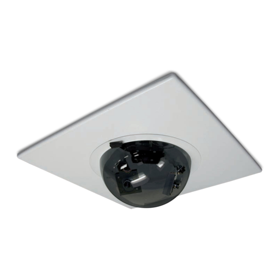
Drop Ceiling Office Surveillance Housing
Installation and Operation Instructions for the following models:
QODT2-70NA
Drop Ceiling indoor housing, tinted dome, replaces 2' x 2' ceiling
tile, with (2) Day / Night cameras, 3-9mm auto-iris lens.
QODT4-70NA
Drop Ceiling indoor housing, tinted dome, replaces 2' x 2' ceiling
tile, with (4) Day / Night cameras, 3-9mm auto-iris lens.
Before attempting to connect or operate this product, please read these instructions completely.
www.videolarm.com
81-IN5257
12-20-2011
Advertisement
Table of Contents

Related Manuals for Moog Videolarm QOD SERIES


Summary of Contents for Moog Videolarm QOD SERIES
- Page 1 © 2011, Moog Videolarm, Inc. All Rights Reserved Q O D Drop Ceiling Office Surveillance Housing www.videolarm.com Installation and Operation Instructions for the following models: QODT2-70NA Drop Ceiling indoor housing, tinted dome, replaces 2’ x 2’ ceiling tile, with (2) Day / Night cameras, 3-9mm auto-iris lens. QODT4-70NA Drop Ceiling indoor housing, tinted dome, replaces 2’ x 2’ ceiling tile, with (4) Day / Night cameras, 3-9mm auto-iris lens. 81-IN5257 12-20-2011 Before attempting to connect or operate this product, please read these instructions completely.
- Page 2 IMPORTANT SAFEGUARDS SAFETY PRECAUTIONS Read these instructions. Keep these instructions. CAUTION Heed all warnings RISK OF ELECTRIC SHOCK DO NOT OPEN Follow all instructions. Do not use this apparatus near water. CAUTION: TO REDUCE THE RISK OF Clean only with damp cloth. ELECTRIC SHOCK, DO NOT REMOVE COVER ( OR BACK).
- Page 3 If Purchaser believes that the Product is defective in material or workmanship, then written notice with an explanation of the claim shall be given promptly by Purchaser to Moog Videolarm. All claims for warranty service must be made within the warranty period.
-
Page 4: Table Of Contents
TABLE OF CONTENTS 4. Align the eyelet on the cord with the hole located on the inside of the housing tile opening. Cable and Power Guidelines 1, 10 Electrical Specifications 5. Insert the 6-32 x 1/2 round Phillips head screw through the hole and eyelet. Place General Instructions the star lockwasher and 6-32 hex nut on the screw and tighten. Wiring 6. Fit the 2 x 2 housing tile in the desired location. The housing tile will rest on the Camera Adjustment ceiling grid. (Be sure the grid is adequately supported). Camera Focusing Camera Settings Completion of Installation WIRING NVT Instructions 1. Make the proper connections to the incoming power. The RED wire is Warranty Information POSITIVE (+), the BLACK wire is NEGATIVE (-) (For reference purposes. Polarity is not Service and Safeguard Information important in this unit). The GREEN wire, labeled Ground, is GROUND for VAC or VDC Troubleshooting connections. NOTE: Connect green ground wire to earth ground (metal conduit, metal... -
Page 5: Camera Settings
SERIAL NUMBERS BEGINNING WITH MC Vari-Focal Lens: First, adjust the Magnification Lock Screw to the desired magnification (telephoto to wide angle). Tighten the Lock Screw. Next, adjust the The operational settings for the camera are defined by ten dip switches located on the Focus Lock Screw until a clear picture is achieved. Tighten the Lock Screw (Figure 3). PC Board (Figure 6). Moving the switches to the on position will activate each setting. Factory defaults are pictured below (Figure 7 and 8). Magnification lock screw Focus lock screw Hi-Res Color, Fixed and Vari-focal fixed lenses Factory Use Only Dip Switches Fixed iris vari-focal lens Auto Iris Figure 3 adjustment Connection to screw Power Board Auto Iris Lens:... - Page 6 SERIAL NUMBERS BEGINNING WITH CB MC CAMERA DIP SWITCH SETTINGS CHART NOTE: This hi-res color camera uses a 1/4" chip and a 3-6mm auto iris lens. It is SWITCH SETTING DEFINITION comparable to a 1/3" chip using a 4-9mm auto iris lens. Flickerless Mode Setting this switch to "On" and switch 3 (MIRIS) to "Off" will help to reduce The operational settings are defined by four dip switches located on the side of the PC the flicker in fluorescent lights Board (Figure 9 and 10). Moving the switches to the UP position will activate specific settings. Refer to the chart below. BLC (Back Light Helps prevent an object from being washed out when the object is Compensation) directly in front of a light source. Dip Switches MIRIS (Manual/ When the switch is in the on position the auto iris lens controls the amount Electronic Iris of light on the chip. If in the off Auto Iris position the light level is controlled Adjustment...
-
Page 7: Completion Of Installation
COMPLETION OF INSTALLATION Wiring Notes Wire — What to DO When the desired focus is achieved for each camera, adjust the segmented bracket arms to the desired viewing angle. Once you've finished, put the dome back in place 1. DO use point-to-point Unshielded Twisted Pair wire, gauge 24 or thicker, stranded and check to be sure none of the cameras touch the dome. If one or more do, readjust or solid, Category 2, 3, 4, or 5. the arm(s) until they are clear of the dome. 2. The video signal may co-exist in the same wire bundle as other video, telephone, data, control signals, or low-voltage power. It is also OK to run NVT video signals in or near electromagnetic fields (in accordance with National Electrical Code, local, or NVT INSTRUCTIONS other local safety requirements). 3. DO measure the wire distance. Use only transceivers that are designed for that UNSHIELDED TWISTED PAIR distance. VIDEO WIRING 4. DO make sure the pair of wires carrying the video signal is sent as a twisted pair (e.g. the blue-white/white-blue wires twisted together as a pair), not a “split-pair” NOTE: The customer must purchase the Video Transceiver from (e.g. blue-white conductor, part of one pair/orange-white conductor, part of another NVT. Part numbers are: pair). -
Page 9: Warranty Information
Screw (Ground Return) Video Shield Figure D Figure A Ground Loop SERIAL NUMBER CT CAMERAS IMPORTANT NOTE: If you have removed the ground loop and the horizontal line still Auto Iris remains on screen call Moog Videolarm technical support for further information. Adjustment Screw LINE LOCK Figure E All cameras are all shipped from the factory with the line lock function disabled. If your IMPORTANT NOTE ON AUTO IRIS ADJUSTMENT: application requires Line Lock contact Moog Videolarm. WHEN ADJUSTING, USE A SMALL, INSULATED SCREWDRIVER. The auto iris adjustments are very sensitive. -
Page 10: Service And Safeguard Information
If the voltage is greater than 1/2 volt, use an amplified receiver, such as the NVT TROUBLESHOOTING NV-652R, NV-862R, or NV-1662R. If you are experiencing problems, attempt to simplify your setup. Test each cable Alternately, remove the ground at one end (usually at the camera end). Be sure that segment separately. For example, test the camera and monitor together without the floating the camera conforms to local/regional and National Electrical Codes. other equipment. Then add in the NVT transceivers, back-to-back. Test each segment of a long cable-run independently. Attempt to isolate the problem. 4. Check for crosstalk from a second video path. Disconnect all other video sources. Below are problems that may be encountered. If the suggestions below are not helpful, If the problem goes away, check for a split-pair or un-twisted wire. or the recommendations are not effective, please call NVT’s customer support. NVT customer support can be reached 8:00 AM to 5:30 PM PST at (800) 959-9870 or at FAINT STRIPES GLIDING UP OR DOWN THE SCREEN (+1) (650) 562-0600. -
Page 11: Cable And Power Guidelines (Detailed Info
3356/1023 5335/1626 7.9W 24 VAC/VDC 529/161 842/256 2129/649 3385/1032 10.9W 24 VAC/VDC 359/109 572/174 1447/441 2300/701 NOTE: The above table is based on a "worst-case" power supply. Using a regulated or switching power supply can increase your cable distance. Moog Videolarm recommends using our PS24 power supply, or a CSA/UL listed Class 2 power supply. Video Cable Maximum Length (feet/meters) Cable Type RG-59 RG-6 RG-11 Wire Gauge 23 AWG* 18 AWG* 16 AWG* Max. Length 750/229 1500/457... - Page 12 Product Registration/Warranty Thank you for choosing Moog Videolarm. We value your patronage and are solely committed to providing you with the highest quality products available and superior customer service. Should a problem arise, rest assure that Moog Videolarm stands behind its products by offering impressive warranty plans: 3 Years on all Housings, Poles, Power Supplies, and Accessories and 5 Years on camera systems (SView, QView, Warriors), and InfraRed Illuminators. Register Your Products Online Take a few moments and validate your purchase via the Online Product Registration Form at www.videolarm.com/productregistration.jsp Register your recent Moog Videolarm purchases and benefit from the following: • Simple and Trouble-Free RMA process • Added into customer database to receive product updates / news • Eliminate the need to archive original purchase documents: Receipts, Purchase Orders, etc…...
Need help?
Do you have a question about the QOD SERIES and is the answer not in the manual?
Questions and answers