Table of Contents
Advertisement
Quick Links
Order parts online
www.follettice.com
C/E12CI400A
countertop dispenser
Following installation, please forward this manual
12 Series - 220V 60Hz/230V 50Hz
Ice and Water Dispensers
Installation, Operation and Service Manual
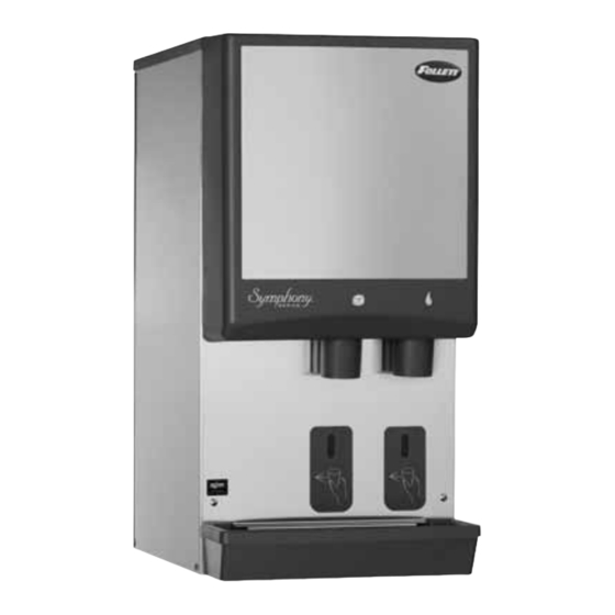
C/E12CI400A
countertop dispenser with
SensorSAFE
(shown with legs accessory)
to the appropriate operations person.
801 Church Lane • PO Box D, Easton, PA 18044, USA
(610) 252-7301 • Fax (610) 250-0696 • www.follettice.com
wall mount dispenser (available
™
actuation
C/E12HI400A
with or without drain pan)
00124438R02
Advertisement
Table of Contents
Troubleshooting

Related Manuals for Follett C/E12CI400A


Summary of Contents for Follett C/E12CI400A
- Page 1 Order parts online www.follettice.com C/E12CI400A countertop dispenser Following installation, please forward this manual to the appropriate operations person. 12 Series - 220V 60Hz/230V 50Hz Ice and Water Dispensers Installation, Operation and Service Manual C/E12CI400A countertop dispenser with SensorSAFE ™ actuation (shown with legs accessory) 801 Church Lane •...
-
Page 2: Table Of Contents
Follett receives the equipment at the factory in Easton, PA within 30 days after issuance of the return authorization number. The equipment must be returned in Follett packaging. If the packaging has been damaged or discarded, Follett will forward, at the customer’s expense, new packaging. -
Page 3: Welcome To Follett Corporation
Before you begin After uncrating and removing all packing material, inspect the equipment for concealed shipping damage. If damage is found, notify your shipper immediately and contact Follett Corporation for help in filing a claim, if necessary. Check your paperwork to determine which model dispenser you have. Follett model numbers are designed to provide information about the type and capacity of Follett ice dispensing equipment. -
Page 4: Specifications
38°C/100°F Max. Water temp 32°C/90°F Max. Water pressure 5Bar Max./70 P.S.I. Plumbing C/E12CI400A Dispenser drain 3/4" FPT Water inlet 3/8" FPT Note: Water shut-off recommended within 3m (10 ft) of dispenser. Drain to be hard-piped and insulated. Maintain at least 20mm per 1m run (1/4" per foot) of slope. -
Page 5: Installation
Installation procedures Before you begin • All dispensers must be installed level in both directions to ensure proper operation. • Service and ventilation clearances: 6" (153mm) on right side of dispenser, 6" (153mm) at top for ventilation and 12" (305mm) at top recommended for service. •... -
Page 6: Installing Countertop Dispenser With Legs Accessory
Fig. 2 – Bottom exiting utilities (countertop units) 19mm (3/4") FPT drain Poly tubing and elbow may be 10mm (3/8") push-in removed for alternate water inlet water inlet elbow hook up by pushing in on the locking collar while pulling out on the tubing. -
Page 7: Installing Wall Mount Dispensers
Notes: No drain pan is provided since the dispenser is intended to be installed above a sink. (Contact Follett if a drain pan is desired.) SensorSAFE actuation is standard. (Contact Follett if lever actuation is desired. A deeper cabinet will be needed.) Recommended minimum counter depth and mounting height shown on Fig. - Page 8 Installing wall mount dispensers Fig. 6 – Wall mounting dimensions 331mm (13") 166mm (6.5") 204mm (8") 77mm (3") 254 mm (10") 407mm (16") minimum distance to sink front outline of dispenser Caution: Do NOT rest dispenser weight on bottom of support bracket. 12mm (.437") 356mm (14")
- Page 9 Fig. 8 – Wall mount unit bottom panel assembly bottom panel screw Fig. 10 – Front view of wall mount bracket – utility location 10mm (3/8") 19mm (3/4") copper drain tube copper water tube 77mm (3") 254mm (10") 407mm (16") utility cutout in wall locate tubing...
-
Page 10: User Information
User information How the dispenser works Follett’s 12 series automatic-load ice and water dispensers are equipped with Follett’s 181kg (400 lb)/day icemaker. In the continuous icemaking process, water freezes to the inside wall of the evaporator. A rotating stainless steel auger carries the ice to the top of the evaporator where it is compressed and extruded through an outlet port. -
Page 11: Icemaker Cleaning And Sanitizing
Cleaning of the condenser can usually be performed by facility personnel. Cleaning of the icemaker system in most cases should be performed by your facility’s maintenance staff or a Follett authorized service agent. Regardless of who performs the cleaning, it is the operator’s responsibility to see that this cleaning is performed according to the schedule below. -
Page 12: Start-Up Following Cleaning
6. Following manufacturer’s instructions, prepare one gallon (3.8L) of Follett SafeCLEAN Ice Machine Cleaner (one 7 oz packet) or equivalent. Solution temperature must be at least 120° F (48.9° C). Warning: Most ice machine cleaners contain citric or phosphoric acid that can cause skin irritation. Read caution label on product and follow instructions carefully. -
Page 13: Important Preliminary Information
The icemaking process The Follett icemaker uses a stainless steel jacketed evaporator and operates on a continuous freezing cycle. Water is supplied to the evaporator from the water reservoir where the water level is controlled by a float valve. This valve also shuts off the water supply when the icemaker is not running. -
Page 14: Wiring Diagram - Lever Model
Wiring diagram – lever model I.D. SOFTWARE BLACK WHITE WHITE WHITE Black CAPACITOR START COMP. BLACK BLACK BLACK BLACK Silver CAPACITOR COMP. START... -
Page 15: Wiring Diagram - Sensorsafe Model
Wiring diagram – SensorSAFE model I.D. SOFTWARE BLACK WHITE WHITE YELLOW YELLOW BLACK NEUTRAL BLACK BLACK WHITE WHITE Black CAPACITOR START COMP. Silver CAPACITOR COMP. START BLACK WHITE WHITE... -
Page 16: Icemaker Operational And Diagnostic Sequences
Icemaker operational and diagnostic sequences The wiring diagrams that follow illustrate the circuitry of Follett icemakers used with 12 series ice dispensers. Both normal operation (Stages 1 – 6) and non-normal diagnostic sequences showing torque-out (Stages 7 – 10) for use in troubleshooting are shown. - Page 17 Normal operation – Stage 2 The water sensor verifies water in the float reservoir. The water OK LED (WTR) comes on. At the same time, the gearmotor, compressor and condenser fan motor come on, lighting the drive LED (DR) and compressor LED (C). The gearmotor is started through a current style relay that is pulled in by the initial high current draw of the run winding.
- Page 18 Normal operation – Stage 4 Once the ice level control opens, the B-E LED goes out. After a 10 second delay the compressor LED (C), compressor and fan motor go off. (Should the ice level control not remain open for 10 seconds, the icemaker will continue to run.) The gearmotor continues to run and the DR LED remains on for 60 seconds.
- Page 19 Normal operation – Stage 6 When the dwell time of 20 minutes has expired, the B-T LED goes off. The icemaker goes through the normal start-up sequence when the bin level control signals the control board for ice. The WTR LED will remain on as long as the water sensor in the float reservoir senses water.
- Page 20 Diagnostic sequence – Stage 8 If the restart is successful the 20M LED goes off, the 60 minute timer LED (60M) comes on. The 60M LED will remains on for 60 minutes from restart. A lighted 60M LED indicates the icemaker has experienced an over-torque condition.
-
Page 21: Refrigeration Cycle Diagram
Diagnostic sequence – Stage 10 If the water level in the float reservoir drops to an unacceptable level, the WTR LED goes out, shutting the icemaker off. Also, the BT LED comes on, preventing the icemaker from restarting for twenty minutes. If water is restored, the WTR LED comes back on and flashes to alert the technician that water to icemaker has been lost. -
Page 22: Refrigeration Pressure Data
Refrigeration pressure data Ambient air temperature C 12/1.6 16.9/2.1 12/1.6 16.8/2.1 13.1/1.7 18.3/2.2 Table 2 – Compressor data Compressor current draw Air-cooled Ambient air temp. 15.6°C/60°F 3.2A Locked rotor amps 26.3 Table 3 – Gearmotor data Gearmotor current Locked rotor amps Air-cooled icemaker capacity/24 hrs. -
Page 23: Refrigeration System Data And Requirements
Refrigerant replacement requirements 1. Non-contaminated refrigerant removed from any Follett refrigeration system can be recycled and returned to the same system after completing repairs. Recycled refrigerant must be stored in a clean, approved storage container. If additional refrigerant is required, virgin or reclaimed refrigerant that meets ARI standard 700-88 must be used. -
Page 24: Dispenser Troubleshooting - Lever Models
Ice capacity test Icemaker production capacity can only be determined by weighing ice produced in a specific time period. 1. Remove top panel and hopper lid of unit. 2. Weigh and record weight of container used to catch ice. 3. Run icemaker for at least 15 minutes. 4. -
Page 25: Dispenser Troubleshooting - Sensorsafe Models
Troubleshooting the dispenser – SensorSAFE models Problem: Does not dispense ice and/or water Action Check LEDs on control board. Place cup under drop zone. Troubleshooting the dispenser – SensorSAFE models Problem: Dispenses ice and/or water continuously Action Check LEDs on control board. -
Page 26: Icemaker Troubleshooting
1. Clean condenser. 2. Remove obstruction. 3. Clean evaporator. 4. Provide proper exhaust air provisions per Follett installation manual. 5. Replace expansion valve. 6. Check for leaks; repair, evacuate, and weigh in correct charge. 7. Check that TEV sensing bulb is securely clamped in place and not damaged;... - Page 27 1. Mineral build-up on evaporator surface. noises from evaporator. Corrective action 1. Eliminate kink and check that tube routing complies with Follett icemaker installation manual. 2. Adjust or replace control. 3. Replace complete run of ice transport tube. 4. Inspect bearings for roughness or binding and replace if necessary.
-
Page 28: Disassembly And Replacement Instructions
Disassembly and replacement instructions Dispense chute removal 1. Remove top cover (see page 30). 2. Remove stainless front cover (see page 30) 3. Slide plastic dispense chute cover up and out to remove. 4. Remove four (4) push fasteners holding dispense tube in place and remove tube. - Page 29 Evaporator disassembly Note: The upper bearing, lower bearing and auger assemblies must be replaced as assemblies. The bottom and top bearing assemblies cannot be field assembled to factory specifications. 1. Disconnect power to icemaker. 2. Shut off water to icemaker. 3.
-
Page 30: Panel Removal
Panel removal Top cover: Lift cover up and off Velcro strips. splash panel screw Splash panel: Remove 2 screws. Pull out bottom of panel to allow top to slide out from under hopper support lip. Fan removal (a) Remove 4 fan mounting screws and 3 drain tubes from bracket. -
Page 31: Thermostat And Ice Transport Tube Replacement
Thermostat and ice transport tube replacement 77mm (3") capillary 51mm tube (2") bracket Thermostat: hand bend cap tube end as shown Ice transport tube replacement 1. Push tube onto evaporator port. 2. Position clamp behind lip on evaporator port and tighten clamp. Top View 13mm (.50") -
Page 32: Dispenser Exterior
Parts Dispenser exterior Part # Description 502932 Cover, front 502819 Cover, dispense assembly 502400 Cover, dispense assembly, ice 502402 Louver, intake 502412 Grille, drain pan 502883 Drain pan, plastic 502410 Drain pan assembly (includes base, pan and grill) 502394 Panel, rear 502399 Leg kit, 102mm (4"), adjustable –... -
Page 33: Wheelmotor And Drive System
Wheelmotor and drive system storage hopper interlock switch Top view Part # Description 502933 Motor, wheel – 220V 60 Hz/230V 50Hz (includes 502537) 502384 Drive shaft extension 502385 Coupling (includes key) 501273 Key, 1/8" sq x 1-1/4" lg 502414 Baffle, ice (securing hardware included) 502387 Wheel, agitator 502390... - Page 34 Dispense chute and splash panel — lever model water solenoid assembly Part # Description 502513 Chute assembly, ice 502249 Chute, water 502247 Bracket, dispense chute (includes four (4) 502057 fasteners) 502417 Lever 501100 Thumbscrew 502409 Switch, dispense, water/ice (includes nut, boot and spacer) 502418 Boot, dispense switch button (mounts over the dispense button) 502057...
- Page 35 Dispense chute and splash panel – SensorSAFE model Part # Description 502513 Chute assembly, ice 502249 Chute, water 502247 Bracket, dispense chute (includes four (4) 502057 fasteners) 00122978 Sensor (includes 502690 and 203611) 501100 Thumbscrew 502819 Cover, dispense chute 502934 Solenoid assembly (includes solenoid, fittings, tube &...
-
Page 36: Ice Machine Cleaner
Tubing, plastic, 3/4 ID (sold by the foot) Water filter kits and cartridges Part# Description 00130299 Follett QC4-FL4S water filter system (includes FL4S primary cartridge and head, coarse pre-filter and head, pressure gauge, mounting bracket) 00130245 Follett FL4S primary replacement cartridge... - Page 37 Icemaker components Right side view Rear view OPERATE UNIT WITH PANELS REMOVED. Top view (lower section) Left side view...
-
Page 38: Electrical Components
Electrical components Side View Part # Description 502938 Board, control circuit – 220V 60Hz/230V 50Hz 502915 Control board, SensorSAFE models – 220V 60Hz/230V 50Hz 502116 Water sensor 502209 Switch, on/off, compressor, bin signal 502409 Switch, cleaning, SensorSAFE models 500514 Bin thermostat 502835 Capacitor, start, compressor –... -
Page 39: Evaporator Replacement Parts
Evaporator replacement parts Part # Description 502735 Coupling, vee band, includes nut 502736 Bearing assembly, top 502110 Loop, ice compression, beveled 502737 Auger 502725 Evaporator (includes insulation jacket, 502740) 500496 O ring, bearing housing 502738 Bearing assembly, bottom (includes O rings and condensate shield) 501063 O ring, mounting base 500744... - Page 40 801 Church Lane • PO Box D, Easton, PA 18044, USA 00124438R02 (610) 252-7301 • Fax (610) 250-0696 • www.follettice.com 10/06...
Need help?
Do you have a question about the C/E12CI400A and is the answer not in the manual?
Questions and answers