Table of Contents
Advertisement
Quick Links
Advertisement
Table of Contents

Subscribe to Our Youtube Channel
Related Manuals for ADDER AdderLink AV100 series


Summary of Contents for ADDER AdderLink AV100 series
- Page 1 AdderLink AV100 series Digital Signage Extenders ...
-
Page 2: Table Of Contents
Contents Welcome Operation Introduction .................2 Indicators..................18 Standard AdderLink AV models ..........2 Adjustments ................18 Brightness and sharpness adjustments ........18 Support for DDC (Display Data Channel) ......3 Further expansion ..............4 Skew compensation adjustments (AV101 only) ....19 Transmitter cascading ............4 Further information Receiver cascading .............4 What’s in the box ................5 Troubleshooting ................21 What you may additionally need ..........5... -
Page 3: Introduction
Mindful of the need for variety and flexibility AV104 transmitter is capable of directly feeding up to four AV101 receivers. to suit disparate installations, Adder have created a family of products that can Each receiver supports two remote display and speakers sets, but additionally fulfil your current requirements and be easily expanded at any future stage. -
Page 4: Support For Ddc (Display Data Channel)
Support for DDC (Display Data Channel) The Display Data Channel standard allows video monitors to define their characteristics so that the source computers to which they are connected can optimise their video outputs accordingly. By their nature, the AdderLink AV extenders enable multiple video displays to be attached to a single source computer. -
Page 5: Further Expansion
Further expansion Transmitter cascading Receiver cascading This method of expansion is limited As mentioned earlier, the AV100 and AV104 transmitters are all to the AV101 receivers as only they capable of supporting additional are equipped with the necessary cascade port. Using the transmitter modules (and their LINK OUT port, the video and audio... -
Page 6: What's In The Box
What you may additionally need Video cable to connect a transmitter to the source PC and optionally to connect additional transmitter modules in cascade. Adder P/N: VSC18 * AdderLink AV100 models are AdderLink AdderLink AV packaged as transmitter and AV transmitter* receiver* receiver pairs. -
Page 7: Module Features
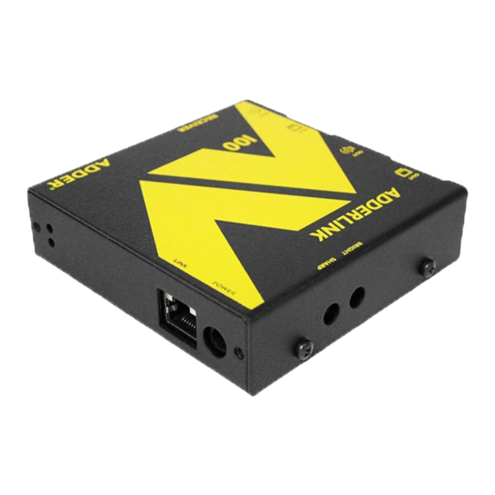
Module features Audio output to speakers Power supply connection Link output to receiver 1 Video output to display Receiver module Transmitter module Link outputs to (AV104 model pictured) (AV101 model pictured) Audio output to speakers receivers 2, 3 & 4 (AV104 only) Video output Indicators... -
Page 8: Installation
Installation Locations Please consider the following important points when planning the positions of your AdderLink AV modules: • Take care not to exceed the maximum link cable lengths (please refer to the section Making cascade connections). • Ensure that the transmitters are as close as possible to the source PC system and the receivers are similarly close to the display modules. -
Page 9: Mounting
Mounting Before you begin connecting to the source PC system and display devices, it is advisable to mount the AdderLink AV modules in place. There are a number of mounting possibilities for the transmitter and receiver modules: • On a horizontal surface using the supplied self adhesive feet, •... -
Page 10: Using The Optional Rack Mount Chassis
Using the optional rack mount chassis 1 Place the optional rack plate onto the front of the transmitter or receiver module and secure it with the countersunk screws. 2 Orient the module on its side so that its labelled face is the correct way up and the securing plate is facing away from the rack. -
Page 11: Making Standard Connections
1 Attach a video cable of suitable type and length (fully shielded with 15 way The video and audio out ports of the AdderLink AV transmitter can optionally be male D-type connectors at both ends, 2m or less - Adder part number: used either to: VSC18) to the socket labelled on the AdderLink AV transmitter. - Page 12 To connect the link cable(s) The links between the transmitter and receiver modules are made using between one and four twisted pair cables, specified to Category 5 or higher. Each cable carries video and audio signals to each receiver module. When a single receiver is attached to a link cable, the maximum length of that link cable is 300m (1000 feet).
- Page 13 To connect the power supply NOTE: Please read and adhere to the electrical safety information given within Safety information section of this guide. In particular, do not use an unearthed power socket or extension cable. 1 Attach the output connector of the power supply to the socket labelled on the AdderLink AV POWER...
-
Page 14: Connections At The Receiver
Connections at the receiver To connect displays and speakers Link in Dual video and audio outputs are provided on the AdderLink AV receiver. Both The link from the transmitter to each receiver module is made using a twisted sets of ports provide identical signals and their connection procedures are the pair cable, specified to Category 5 or higher. - Page 15 To connect the power supply NOTE: Please read and adhere to the electrical safety information given within Safety information section of this guide. In particular, do not use an unearthed power socket or extension cable. 1 Attach the output connector of the power supply to the socket labelled on the AdderLink AV receiver.
-
Page 16: Making Cascade Connections
Making cascade connections Cascade connection examples The AdderLink AV series of products have been specifically designed to be These examples demonstrate valid configurations and the effect of cascade flexible in order to support both your immediate and future needs for media connections upon overall link lengths: streaming. -
Page 17: Cascading Transmitters
To connect cascaded transmitters 1 Attach a video cable of suitable type and length (fully shielded with 15 way male D-type connectors at both ends, 2m or less - Adder part number: VSC18) to the socket labelled on the primary AdderLink AV transmitter. -
Page 18: Cascading Receivers (Adderlink Av101 Only)
Cascading receivers (AdderLink AV101 only) Expansion at the receiver end is made possible using ports present on AdderLink AV101 LINK OUT CASCADE LINK receivers. Receiver cascade links are made using twisted pair cables, specified to Category 5 or higher. RECEIVER NOTE: Ensure that there are no more than three cascades (transmitter or receiver cascades) between the primary transmitter and the... -
Page 19: Operation
Operation Brightness and sharpness adjustments In operation, the AdderLink AV modules are designed to be completely The brightness and sharpness adjustments transparent - high quality video and audio from the source PC system are played provided on every AdderLink AV receiver allow as normal, the only difference is that they are now being seen and heard up to you to compensate for any losses incurred 300 metres away. -
Page 20: Skew Compensation Adjustments (Av101 Only)
To display the supplied skew test pattern certain types of category 5e cables. 1 Insert the supplied Adder CD-ROM into the Skew compensation adjustments are made using two rotary dials, the first CD player of the computer. - Page 21 To zero the skew adjustment dials To adjust the skew compensation When supplied, the two skew dials are set in Your chances of achieving a successful skew compensation adjustment will be their neutral positions. i.e. no delay to either improved if you do the following: of its colours.
-
Page 22: Further Information
For technical support, use the contact form in the Support section of the • Please refer to the ‘Brightness and sharpness adjustments’ section in the adder.com website - your regional office will then get in contact with you. ‘Operation’ chapter. -
Page 23: Safety Information
If the product should fail to operate correctly in normal use during the • Not suitable for use in hazardous or explosive environments or next to highly warranty period, Adder will replace or repair it free of charge. No liability can be flammable materials. -
Page 24: Products In The Adderlink Av Range
Products in the AdderLink AV range Cables The following items are available within the AdderLink AV product range: These cables are available for use when connecting the modules to systems and peripherals: • AdderLink AV100 pair (part number: ALAV100P) • Video cable - 2 metres (part number: VSC18) One AdderLink AV100 transmitter and one AdderLink AV100 receiver. -
Page 25: Emissions And Immunity
Emissions and Immunity A Category 5 (or better) twisted pair cable must be used to connect the modules in order to maintain compliance with radio frequency energy emission regulations and ensure a suitably high level of immunity to electromagnetic disturbances. All other interface cables used with this equipment must be shielded in order to maintain compliance with radio frequency energy emission regulations and ensure a suitably high level of immunity to electromagnetic disturbances. - Page 26 Web: www.adder.com www.adder.com/contact-details Contact: Support: forum.adder.com © 2012 Adder Technology Limited All trademarks are acknowledged. Documentation by: www.ctxd.com Part No. MAN-ALAV • Release 1.3b...
Need help?
Do you have a question about the AdderLink AV100 series and is the answer not in the manual?
Questions and answers