ADDER AdderLink Infinity 2112T User Manual
Hide thumbs
Also See for AdderLink Infinity 2112T:
- Quick start manual (4 pages) ,
- User manual (64 pages)

Subscribe to Our Youtube Channel
Related Manuals for ADDER AdderLink Infinity 2112T


Summary of Contents for ADDER AdderLink Infinity 2112T
- Page 1 AdderLink Infinity 2112T User Guide Experts in KVM Extension Connectivity Solutions Solutions...
-
Page 2: Table Of Contents
Contents Introduction Operation Welcome ........................2 Front panel indicators ..................20 AdderLink dual 2112T unit features ..............3 Using the VNC viewer..................21 Supplied items .......................4 Further information Optional extras .....................5 Getting assistance ....................22 Installation Appendix A - Transmitter (TX) unit configuration pages ......23 Mounting ........................6 Appendix B - The VNC port: Initial configuration ........30 Connections ......................7... -
Page 3: Welcome
Introduction Welcome Thank you for choosing the AdderLink Infinity dual 2112T transmitter, otherwise one-to-one configuration The simplest configuration links one RX unit to a single TX unit, either by a direct link or over much known as ALIF 2112T. ALIF 2112T represents a major advance in the capabilities of greater distances via a high speed network. -
Page 4: Adderlink Dual 2112T Unit Features
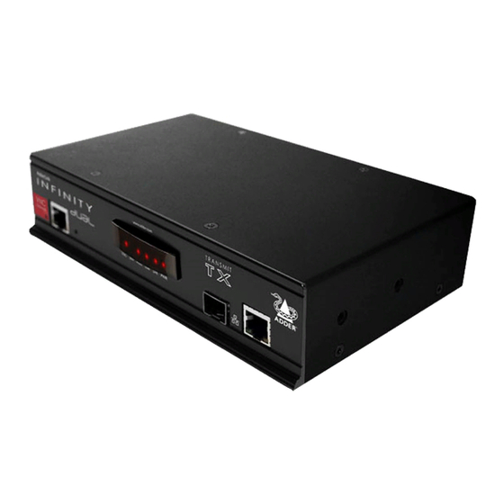
AdderlINk duAl 2112T uNIT FeATures The ALIF 2112T units are housed within durable, metallic enclosures with most connectors situated at the rear panel - the Ethernet ports are situated on the front panels. The smart front faces also feature the operation indicators. Front Rear INDOOR... -
Page 5: Supplied Items
suPPlIed ITems Power adapter (20W) and country-specific power cord combined dVI-d and usB Single link DVI-D to DVI-D video cable cable (1.8m) ALIF 2112T transmitter unit Serial null modem cable 2m 2 x Audio cable 2m Information wallet (3.5mm stereo jacks) containing: Four self-adhesive rubber feet Quick start guide... -
Page 6: Optional Extras
oPTIoNAl eXTrAs Single mode fibre SFP module Part number: SFP-SM-LC Please refer to the table in Appendix M information about fibre modules and cables. Two 19” rack-mount brackets and four screws Part numbers: One unit per 1U rack slot: RMK4S Single link DVI-D to DVI-D video cable Two units per 1U rack slot: RMK4D Part number: VSCD1... -
Page 7: Installation
Installation mouNTING There are two main mounting methods for transmitter and receiver units: • The supplied four self-adhesive rubber feet • Optional rack brackets Connections Rack brackets The optional brackets (plus four screws), allow the units to be secured within a standard rack slot. Note: The ALIF 2112T and its power supply generate heat when in operation and will become warm to the touch. -
Page 8: Connections
coNNecTIoNs Installation involves linking the ALIF 2112T unit to various ports on the host computer, while an ALIF RX unit is attached to your peripherals: Click a connection to see details IMPORTANT: When using an AdderLink Infinity Management box to configure ALIF units, it is vital that all ALIF units that you wish to locate and control are set to their factory default settings. -
Page 9: Vnc Network Link
VNC network link The ALIF 2112T contains a VNC server that allows you to transmit a low-bandwidth version of the video output across standard networks to authorized remote viewers. The VNC link can either be made over the same network as the main ALIF output or via a separate one. -
Page 10: Video Link
Video link ALIF dual units can simultaneously support up to two Single Link high resolution video displays at pixel clocks up to 165MHz; or can alternatively support a single Dual Link very high Resolution video display at pixel clocks up to 330MHz (equating to an example display mode of 2560 x 1600 at 60 Hz refresh). -
Page 11: Audio Links
Audio links USB link ALIF dual units support two way stereo ALIF dual units act as USB 2.0 hubs and so digital sound so that you can use a remote can provide four sockets at the RX unit with microphone as well as speakers. only a single connection at the TX unit. -
Page 12: Aux Port
AUX port Power in The AUX port is an RS232 serial port that Each ALIF dual unit is supplied with a power allows extension of RS232 signals up to a adapter and country-specific power cord. baud rate of 115200. The port has software When all other connections have been flow control, but no hardware flow control. -
Page 13: High Speed Links
High speed links ALIF dual (inc 2112T.) units can be either connected directly to each other or via a high speed network. The connections can be copper-based Gigabit Ethernet as well as Fibre Channel over Ethernet (FCoE). These can be used in parallel to provide up to 2 Gigabit connections speeds. -
Page 14: Configuration
Configuration The ALIF 2112T unit consists of two distinct sections (as detailed below) which each have their own separate configuration procedures within this chapter. The VNC port The System and Teaming ports Uses the standard Ethernet port on the left side of the front panel and These use either the Gigabit Ethernet or (optional) Fibre Channel provides lower-bandwidth image video feeds for use across standard over Ethernet (FCoE) module, on the right side of the front panel... -
Page 15: System And Teaming Ports: Initial Configuration
sysTem ANd TeAmING PorTs: INITIAl coNFIGurATIoN ALIF 2112T units are designed to be as flexible as possible and this principle extends also to their configuration. manual factory reset Direct linking Where ALIF transmitters and receivers (all models) are directly linked to each other, A factory reset returns an ALIF transmitter or receiver unit to its default configuration. -
Page 16: Adderlink Infinity Browser-Based Configuration Utility
AdderLink Infinity browser-based configuration utility The browser-based configuration utility within all TX and RX units requires a network To access the browser-based configuration utility connection between the Gigabit Ethernet port of the ALIF 2112T unit and a computer 1 Temporarily connect the ALIF 2112T unit and your computer, as discussed left. on the same network. -
Page 17: A Rough Guide To Configuring Tx And Rx Units
A rough guide to configuring TX and RX units TX (transmitter) unit configuration optimizing the TX video signal In an ALIF dual system, the majority of configuration settings are dictated by the units. Therefore, the local TX unit setup (using its browser-based configuration utility) is Note: Where the ALIF dual system is linked via two Gigabit links with sufficient available usually concerned only with three main factors: Its IP address details, the data streams bandwidth, there should be no need to alter the default settings on this page. -
Page 18: Rx (Receiver) Unit Configuration
RX (receiver) unit configuration In an ALIF dual system, it is the RX unit (receiver) that determines where and how data signals are sent (and received) by the unit. Although numerous topologies (one- to-one, one-to-many, many-to-one, etc.) are made possible by the ALIF system, they are all dependent on two underlying modes of operation: either Unicast or Multicast transmission. - Page 19 5 In the Target Transmitter Unit Settings section, you need to enter the System port and Teaming The two Video and the single Audio Multicast sub-sections are configured in exactly port IP addresses for the TX unit that will be supplying the video, audio, USB and serial data the same way: streams.
-
Page 20: Performing An Upgrade
Firmware files for the ALIF dual units are available from the Technical Support > Updates section of the Adder Technology website (www.adder.com). Note: It is possible to downgrade a version 3.0 AdderLink Infinity 2112T unit to an earlier firmware version that lacks the Teaming facility. After installing the older firmware, perform a factory reset on each AdderLink Infinity 2112T in order to clear the Teaming port configuration file. -
Page 21: Operation
Operation In operation, many ALIF dual installations require no intervention once configured. The TX and RX units take care of all connection control behind the scenes so that you can continue to work unhindered. FroNT PANel INdIcATors The six front panel indicators on each unit provide a useful guide to operation: Indicators These six indicators clearly show the key aspects of operation: •... -
Page 22: Using The Vnc Viewer
usING The VNc VIeWer 1 On a network connected computer, locate and select the VNC viewer Viewer options Ctrl Alt Del Controls Power Dialog area icon (VNC viewer Sends the Displays a menu Click to access Indicates your username only) Click the Ctrl Alt Del of options... -
Page 23: Further Information
Further information GeTTING AssIsTANce This chapter contains a variety of information, including the following: If you are still experiencing problems after checking the information contained within this • Getting assistance - see right guide, then we provide a number of other solutions: •... -
Page 24: Appendix A - Transmitter (Tx) Unit Configuration Pages
APPeNdIX A - Transmitter (TX) unit configuration pages This section covers the browser-based configuration utility for the AdderLink Infinity TX (transmitter) unit. The TX utility has ten pages, titled as follows: • System Configuration • System Messages • Video Configuration •... - Page 25 TX System Configuration unit Name Name details that you can alter to distinguish this unit from all others. The name entered here will be read by A.I.M. units (if used) for administration purposes. Unit Description Allows you to optionally add a description of the unit, such as its location. Useful when many ALIF units are being used.
- Page 26 TX Video Configuration Peak bandwidth limiter percentage The TX unit will employ a ‘best effort’ strategy in sending video and other data over the IP network. This means it will use as much of the available network bandwidth as necessary to achieve optimal data quality, although typically the TX unit will use considerably less than the maximum available.
- Page 27 TX usB settings Enable Dummy Boot Keyboard When ticked, the TX unit reports a virtual dummy boot keyboard to the attached PC to ensure that a keyboard is always reported when the PC boots up. The dummy boot keyboard uses one of the 13 USB endpoints, therefore if all 13 endpoints are required elsewhere for USB devices (or a KVM switch only supports two HID devices) then it can be disabled by deselecting this option.
- Page 28 TX AIM Manager Enable AIM Control Click this button to allow an A.I.M. (Adder Infinity Manager) box to take control of this TX. When the button is clicked, the TX unit will be rebooted to allow the A.I.M. box to discover and control it. TX system messages enable system messages Tick to allow the creation of status and error messages by the unit.
- Page 29 TX statistics enable collection of bandwidth statistics The ALIF dual unit can record data transfer statistics from the System port and plot them on a graph for troubleshooting and optimization purposes. When you enable this option, you will first be presented with a pop up from which you can choose which aspects you would like to graph: Data throughput, various packet rates and/or frame rates.
- Page 30 TX About About This page displays key information about the TX unit that may be requested by Adder Technical Support. To get here Connect your computer to the Management port on the left side of the front panel. 2 Run a web browser and enter the IP address of the Management port: http://192.168.1.42 If the address is unknown, perform a manual factory reset.
-
Page 31: Appendix B - The Vnc Port: Initial Configuration
APPeNdIX B - The VNC port: Initial configuration This section deals with the initial configuration of the VNC port of the ALIF 2112T unit. For details about the main System and Teaming ports, please here. The default IP address of the VNC port is 192.168.1.42; it is possible to change this either through the VNC viewer or via the TX System Configuration page. -
Page 32: Initial Configuration
Initial configuration To perform the initial configuration, you need to connect the ALIF 2112T to an IP network and use a computer located on the same network to connect to it. To perform the initial configuration admin 1 Connect the ALIF 2112T to an IP network (using the VNC port) where a suitable 5 Enter as the Username, leave the password entry blank and click the OK computer is available on the same subnet (please see the section... - Page 33 Controls When clicked, this button reveals a menu of options concerned with keyboard, video and mouse operation. single mouse mode mouse Control This mode is for fast network connections where the cursor This option displays a mouse control dialog and is useful when the remote cursor is response is sufficient to provide instant visual feedback on failing to respond correctly to your mouse movements, even after using the Resync the remote screen.
- Page 34 Advanced mouse configuration Info This dialog allows the mouse acceleration to be configured according to the operating When selected, this option displays an information dialog showing the current logged on system in use and also permits manual fine tuning for situations where problems are users, the current host, its video mode and its mouse motion details.
-
Page 35: Video Settings
Keyboard Control Video settings This option displays a keyboard control dialog and is useful for sending keyboard This option provides a range of options related to the video configuration. combinations (to the host) that are needed regularly or that are trapped by the ALIF 2112T. - Page 36 Virtual Media The Adder Virtual Media feature allows you to remotely make files available to a host To remotely transfer files from the clipboard computer that is linked to the ALIF 2112T. Disk drives, single files or collections of 1 On the remote system, log into the ALIF 2112T using the VNC viewer. files and folders up to 2GB in size can be mounted via the VNC link, and appear as a 2 If not already done, use Windows Explorer to locate and copy the required file(s), or read-only disk on the host.
- Page 37 Remotely exporting a disk drive to the host 1 On the remote system, log into the ALIF 2112T using the VNC viewer. 2 Press F8 and then V to display a Virtual Media dialog box: Remote Drive(s) This section lists any located storage devices on the remote system that are 2GB or less, and which could be...
- Page 38 Editing the viewer window menu bar If required, you can customize the menu bar of the viewer window to ensure that it contains only the necessary options. The menu bar can be edited locally by each user or edited singly by the admin or alternatively, the admin can globally alter the menu bar for all users.
-
Page 39: Appendix C - Tips For Success When Networking Alif Units
APPeNdIX c - Tips for success when networking ALIF units Creating an efficient network layout ALIF units use multiple strategies to minimize the amount of data that they send across networks. However, data overheads can be quite high, particularly when very Network layout is vital. - Page 40 Configuring the switches and devices The layout is vital but so too is the configuration: • Enable IGMP Snooping on all L2 switches. • Ensure that IGMP Fast-Leave is enabled on all switches with ALIF units connected directly to them. •...
-
Page 41: Appendix D - Troubleshooting
APPeNdIX d - Troubleshooting Problem: The video image of the ALIF receiver shows horizontal lines across remedies: the screen. • Ensure that IGMP snooping is enabled on all switches within the subnet. This issue is known as Blinding because the resulting video image looks as though you’re •... - Page 42 Problem: The mouse pointer of the ALIF receiver is slow or sluggish when Problem: The audio output of the ALIF receiver sounds like a scratched re- moved across the screen. cord. This issue is often related to either using dithering on the video output of one or more This issue is called Audio crackle and is a symptom of the same problem that produces transmitting computers or using VGA-to-DVI video converters.
-
Page 43: Appendix E - Glossary
APPeNdIX e - Glossary Internet Group Management Protocol IGmP snooping Jumbo frames (Jumbo packets) Where an ALIF transmitter is required to stream video to The IGMP messages are effective but only operate at Since its commercial introduction in 1980, the Ethernet two or more receivers, multicasting is the method used. - Page 44 Spanning Tree Protocol (STP) ALIF transmitter video settings In order to build a robust network, it is necessary Each ALIF transmitter includes controls to help you to include certain levels of redundancy within the customize how video data is transmitted. When configured interconnections between switches.
- Page 45 Forwarding modes In essence, the job of a layer 2 switch is to transfer as So which one to choose? The Cut-through method has the So why are Layer 2 and Layer 3 of particular importance fast as possible, data packets arriving at one port out to least latency so is usually the best to use with AdderLink when discussing AdderLink Infinity? Because the successful another port as determined by the destination address.
-
Page 46: Appendix F - Configuration Menus (Via Vnc)
APPeNdIX F - Configuration menus (via VNC) When viewing remotely via VNC, the unit has a main configuration menu through which you can access various sub menus to configure particular items. To view the main configuration menu 1 Using VNC viewer or a browser, log on as the ‘admin’ user. 2 Click the ‘Configure’... - Page 47 User accounts Up to 16 users can be created by the admin user, each with their password. One of the 16 users can be the admin user. This user has access to the units configuration menu. Ticking the ‘IsAdmin’ box creates the Admin user. The admin user can also determine whether the users are allowed access to the power control menu in order to turn servers on and off.
- Page 48 Gui edit configuration To edit the menu bar locally If required, you can customize the menu bar of the viewer window to ensure that it contains only the necessary options. 1 Login remotely via VNC viewer and display the viewer window. The menu bar can be edited locally by each user or edited singly by the admin or 2 Place the mouse pointer on the menu bar and click the right mouse button.
- Page 49 Unit configuration This page provides access to a selection of both basic and advanced settings for the ALIF 2112T. Many of the settings displayed here are also accessible through the on-screen menu. To get here 1 Using VNC viewer or a browser, log on as the ‘admin’ user. 2 Click the ‘Configure’...
- Page 50 Advanced unit configuration Click this button to display advanced options that do not normally require alteration. Background Refresh Rate Use the arrow keys to alter the background refresh rate used to correct any screen changes missed in normal operation. The options are: Slow, Medium, Fast, Auto or Disabled.
- Page 51 Time & date configuration This page allows you to configure all aspects relating to time and date within the unit. Timezone specifier Optionally enter a recognized timezone specifier related to the current position of the ALIF 2112T unit. When an NTP server is used, the specifier will be used to provide the correct real time.
-
Page 52: Network Configuration
Network configuration This page allows you to configure the various aspects of the IP port. To get here 1 Using VNC viewer or a browser, log on as the ‘admin’ user. 2 Click the ‘Configure’ button in the top right corner. 3 Click the ‘Network Configuration’... - Page 53 setting IP access control To define a new IP access control entry The golden rule with this feature is ‘Include before you exclude’ or to put it another way ‘Arrange allowed addresses in the list before the denied addresses’. 1 Click the Add button to display a popup dialog: This is because the positions of entries in the list are vitally important.
- Page 54 Serial port configuration This page allows you to configure the baud rate of the ALIF 2112T serial port that is used to control power switch devices. A full range of standard baud rates are available. Baud rate Determines the communication speed of the OPTIONS port. The other communication settings are fixed as: No parity, 8 bit word, 1 stop bit.
- Page 55 Host configuration To create a new host entry This page provides the opportunity to configure various details for each of the host 1 Click one of the host entries to reveal a Host configuration dialog. systems that may be connected to the ALIF 2112T. Each entry can be configured with a name, the permitted users, the hot key combinations required to switch to it and, if required, appropriate power control commands.
- Page 56 Power switching configuration Power control sequences Power switch configuration comprises two main steps: Notes: The settings given below are for Adder power switches model numbers PSU-8SLAVE and • Configure the serial port to the same speed as used by the power switch PSU-1GUARD - other power switches may require different settings.
- Page 57 logging and status This screen provides various details about the user activity on the ALIF 2112T unit. To copy and paste the log You can copy the information listed within the log and paste it into another application. date and Type of event, user name and access time the method or remote IP address...
-
Page 58: Appendix G - Vnc Viewer Connection Options
APPeNdIX G - VNC viewer connection options Note: If you are using a later version of VNC viewer than that provided with the product display originally, some menus may differ slightly from those shown here. When you are connecting to the ALIF scaling 2112T using the VNC viewer, a number of No scaling... - Page 59 Inputs Inputs: Share clipboard with server When set to ‘Enabled’, all primary options This permits the “Paste Clipboard” operation (see Keyboard control), and the “Create below are ticked. The ‘Disabled’ setting VM Drive” feature of Virtual Media (see Virtual Media). unticks all of the primary options (causing ‘view-only mode’...
- Page 60 connection Expert The options on this page are not relevant The options within this section work to ALIF 2112T connections and should be correctly with ALIF 2112T in their default left in their default states. states and should not require alteration except in special circumstances.
-
Page 61: Appendix H - Vnc Viewer Window Options
APPeNdIX h - VNC viewer window options Click the VNC icon in the top left corner of the viewer window (or press F8) to display the window options: Standard window control items Full screen Expands the VNC viewer window to fill the whole screen with no visible window edges or toolbar. -
Page 62: Appendix I - Java Viewer Options
APPeNdIX I - Java viewer options Inputs When you are connecting to the ALIF 2112T using the Java viewer, a number of options View only (ignore mouse & keyboard) are available. When ticked, the viewer will not send keyboard or mouse information to the ALIF 2112T or host computer. -
Page 63: Appendix J - The Kvmadmin Utility
APPeNdIX J - The kVmAdmIN utility Particularly useful for complex ALIF 2112T configurations and the control of remote installations, KVMADMIN is a powerful administration tool. KVMADMIN is based upon the established VNC viewer and uses the same security system. Rather than a graphical interface such as the standard viewer, KVMADMIN uses command line control to provide the following administration facilities: •... -
Page 64: Appendix K - Known Working Video Modes
APPeNdIX k - Known working video modes 640x480 @ 60Hz 720x480 @ 60Hz 768x576 @ 60Hz 800x480 @ 60Hz 1024x600 @ 60Hz 1024x768 @ 60Hz 1152x768 @ 60Hz 1152x864 @ 60Hz 1280x720 @ 60Hz 1280x768 @ 60Hz 1280x800 @ 60Hz 1280x854 @ 60Hz 1280x960 @ 60Hz 1280x1024 @ 60Hz... -
Page 65: Appendix L - Hotkey Sequences
APPeNdIX l - Hotkey sequences ALIF 2112T allows you to enter commands suitable for any KVM switch in order to choose from up to 128 host systems. These switching commands can take the form of hotkey sequences that emulate standard keypress combinations. Keypad keys Hotkey sequences (see ‘Using abbreviations’) -
Page 66: Appendix M - Cable Pinouts, Video Modes And General Specifications
APPeNdIX m - Cable pinouts, video modes and general specifications rs232 ‘null-modem’ cable pin-out General specifications Casing (w x h x d): 198mm (7.92”) x 44mm (1.76”) x 145mm (5.7”) 9pin d-type 9pin d-type Construction: 1U compact case, robust metal design female female Weight:... -
Page 67: Appendix N - Fibre Modules And Cables
APPeNdIX N - Fibre modules and cables To suit your installation layout, two fibre modules are available for the ALIF dual units to suit various fibre optic cables. The specifications for all are summarized in the table below: Fibre Type Fibre size Fibre Type coding... -
Page 68: Appendix O - Additional Features
APPeNdIX o - Additional features New lossless codec (AFZ) magic eye (anti-dither support added) The new compression scheme builds on the existing codec and is primarily focused on This feature is enabled by default. improving the performance for “natural” images (i.e. photographs and movies). It works The Magic Eye feature increases performance and reduces network traffic when the in concert with the existing codec and is automatically selected whenever there is a AdderLink Infinity dual is used with Apple Macs and other host computers that have... -
Page 69: Warranty
WArrANTy • For use in dry, oil free indoor environments only. Adder Technology Ltd warrants that this product shall be free from defects in workmanship and materials for a period of two years from the date of original purchase. • Warning - live parts contained within power adapter. -
Page 70: Radio Frequency Energy
rAdIo FrequeNcy eNerGy A Category 5 (or better) twisted pair cable must be used to connect the units in order to maintain compliance with radio frequency energy emission regulations and ensure a suitably high level of immunity to electromagnetic disturbances. All other interface cables used with this equipment must be shielded in order to maintain compliance with radio frequency energy emission regulations and ensure a suitably high level of immunity to electromagnetic disturbances. - Page 71 Web: www.adder.com Contact: www.adder.com/contact-details Support: forum.adder.com © 2013 Adder Technology Limited All trademarks are acknowledged. www.ctxd.com Documentation by: Part No. MAN-ALIF2112T • Release 3.0a...
-
Page 72: Index
Index Access control Dimensions 65 IANA 18 MAC address 50,51 Password Magic Eye 25,67 configuration 52 Dithering 67 IGMP 42 remote logon 31 Access mode fast-leave 42 Menu bar editing 37 Peak Bandwidth Limiter 43 shared & private 33 querier 42 Menu key Power strings Factory reset 14... - Page 73 Safety information 68 Teaming port 12 Video Screen TX settings 24 optimization 16 best resolution 21 Threshold setting 34 Video modes 65 navigation 21 Time & date configuration 50 Video settings 33,34,43 refresh 32 Transmitter Viewer window 21 Server configuration 16 menu bar editing 37 configuration 54 Troubleshooting 40...
Need help?
Do you have a question about the AdderLink Infinity 2112T and is the answer not in the manual?
Questions and answers