Table of Contents

Related Manuals for ADDER AdderLink AV series


Summary of Contents for ADDER AdderLink AV series
- Page 1 AdderLink AV series Digital Signage Extenders ...
-
Page 2: Table Of Contents
Contents Welcome Operation Introduction .................2 Indicators ...................18 Standard AdderLink AV models..........2 Adjustments ................18 Brightness and sharpness adjustments ........18 Module mixing................3 Further expansion..............4 Skew compensation adjustments (AV101 & AV200 only)...19 Transmitter cascading ............4 Further information Receiver cascading .............4 What’s in the box ................5 Troubleshooting ................21 What you may additionally need ..........5 Getting assistance..............21... -
Page 3: Introduction
Welcome Introduction AdderLink AV104 and AV101 (or AV100) The AdderLink AV range of digital signage extenders are designed and built The AdderLink AV104 transmitter and multiple AV101 modules are designed specifically for use wherever high quality video and sound must be faithfully to provide potentially enormous expansion possibilities from the outset. -
Page 4: Module Mixing
Module mixing AdderLink AV200 pair The AdderLink AV200 transmitter and receiver pair operate in a similar manner Most of the AdderLink AV modules can be mixed together in various to the AV100 series, with the addition of an RS232 serial port. The serial port combinations quite freely. -
Page 5: Further Expansion
Further expansion Transmitter cascading Receiver cascading This method of expansion is limited As mentioned earlier, the AV100, AV104 and AV200 transmitters to the AV101 receivers as only they are all capable of supporting are equipped with the necessary cascade port. Using additional transmitter modules (and LINK OUT port, the video and... -
Page 6: What's In The Box
What’s in the box What you may additionally need Video cable to connect a transmitter to the source PC and optionally to connect additional transmitter modules in cascade. * AdderLink Adder P/N: VSC18 AV100 and AV200 AdderLink AdderLink AV models are both packaged as AV transmitter* receiver* transmitter and receiver pairs. -
Page 7: Module Features
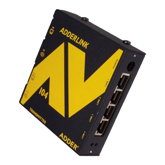
Module features Audio output to speakers Power supply connection Link output to receiver 1 Video output to display Receiver module Transmitter module Link outputs to (AV104 model pictured) (AV101 model pictured) Audio output to speakers receivers 2, 3 & 4 (AV104 only) Video output Indicators... -
Page 8: Installation
Installation Locations Please consider the following important points when planning the positions of your AdderLink AV modules: • Take care not to exceed the maximum link cable lengths (please refer to the section Making cascade connections). • Ensure that the transmitters are as close as possible to the source PC system and the receivers are similarly close to the display modules. -
Page 9: Mounting
Mounting Before you begin connecting to the source PC system and display devices, it is advisable to mount the AdderLink AV modules in place. There are a number of mounting possibilities for the transmitter and receiver modules: • On a horizontal surface using the supplied self adhesive feet, •... -
Page 10: Using The Optional Rack Mount Chassis
Using the optional rack mount chassis 1 Place the optional rack plate onto the front of the transmitter or receiver module and secure it with the countersunk screws. 2 Orient the module on its side so that its labelled face is the correct way up and the securing plate is facing away from the rack. -
Page 11: Making Standard Connections
Making standard connections Connections to the AdderLink AV modules do not need to follow the precise order given in this user guide although it is recommended that you do not apply power to the modules until all other connections have been made. Note: Unless stated otherwise, all connection information given here applies to all modules in the AdderLink AV family. - Page 12 To connect the link cable(s) The links between the transmitter and receiver modules are made using between one and four twisted pair cables, specified to Category 5 or higher. Each cable carries video and audio signals to each receiver module. When a single receiver is attached to a link cable, the maximum length of that link cable is 300m (1000 feet).
- Page 13 To connect the power supply To connect the serial port (AdderLink AV200 only) NOTE: Please read and adhere to the electrical safety information given within Note: The serial port feature supports RS232 serial devices at speeds up to Safety information section of this guide.
-
Page 14: Connections At The Receiver
Connections at the receiver To connect displays and speakers Link in Dual video and audio outputs are provided on the AdderLink AV receiver. Both The link from the transmitter to each receiver module is made using a twisted sets of ports provide identical signals and their connection procedures are the pair cable, specified to Category 5 or higher. - Page 15 To connect the power supply To connect a serial device (AdderLink AV200 only) NOTE: Please read and adhere to the electrical safety information given within Note: The serial port feature supports RS232 serial devices at speeds up to Safety information section of this guide.
-
Page 16: Making Cascade Connections
Making cascade connections Cascade connection examples The AdderLink AV series of products have been specifically designed to be These examples demonstrate valid configurations and the effect of cascade flexible in order to support both your immediate and future needs for media connections upon overall link lengths: streaming. -
Page 17: Cascading Transmitters
Cascading transmitters Primary Expansion at the transmitter end Transmitter VIDEO is achieved using the video and STANDARD LINKS AUDIO audio output ports. The signals from these ports are connected TRANSMITTER to the video and audio inputs of Primary transmitter the next transmitter and so on. AdderLink AV100 and AV104 POWER transmitters can be mixed in a... -
Page 18: Cascading Receivers (Adderlink Av101 Only)
Cascading receivers (AdderLink AV101 only) Expansion at the receiver end is made possible using ports present on AdderLink AV101 LINK OUT CASCADE LINK receivers. Receiver cascade links are made using twisted pair cables, specified to Category 5 or higher. RECEIVER NOTE: Ensure that there are no more than three cascades (transmitter or receiver cascades) between the primary transmitter and the... -
Page 19: Operation
Operation Brightness and sharpness adjustments In operation, the AdderLink AV modules are designed to be completely The brightness and sharpness adjustments transparent - high quality video and audio from the source PC system are played provided on every AdderLink AV receiver allow as normal, the only difference is that they are now being seen and heard up to you to compensate for any losses incurred 300 metres away. -
Page 20: Skew Compensation Adjustments (Av101 & Av200 Only)
Skew compensation adjustments (AV101 & AV200 only) To create a skew test pattern The twisted pair cabling used to 1 Run any image creation/editing application, such as the Paint program 1 2 3 4 5 6 7 8 link the AdderLink AV modules supplied with Windows. - Page 21 To zero the skew adjustment dials To adjust the skew compensation When supplied, the two skew dials are set in Your chances of achieving a successful skew compensation adjustment will be their neutral positions. i.e. no delay to either improved if you do the following: of its colours.
-
Page 22: Further Information
Troubleshooting section then we provide a number of other solutions: • If the sharpness control is set too high, the monitor may not be able to • Adder Technology website – www.adder.com display a picture. Try reducing the sharpness setting. Please refer to the ‘Adjustments’... -
Page 23: Safety Information
Warranty • For use in dry, oil free indoor environments only. Adder Technology Ltd warrants that this product shall be free from defects in workmanship and materials for a period of two years from the date of original • Do not use to link between buildings. -
Page 24: Products In The Adderlink Av Range
Products in the AdderLink AV range Cables The following items are available within the AdderLink AV product range: These cables are available for use when connecting the modules to systems and peripherals: • AdderLink AV100 pair (part number: ALAV100P) • Video cable - 2 metres (part number: VSC18) One AdderLink AV100 transmitter and one AdderLink AV100 receiver. -
Page 25: Emissions And Immunity
Emissions and Immunity A Category 5 (or better) twisted pair cable must be used to connect the modules in order to maintain compliance with radio frequency energy emission regulations and ensure a suitably high level of immunity to electromagnetic disturbances. All other interface cables used with this equipment must be shielded in order to maintain compliance with radio frequency energy emission regulations and ensure a suitably high level of immunity to electromagnetic disturbances. - Page 26 © 2006 Adder Technology Limited All trademarks are acknowledged. Release 1.0d August 2006 Part No. ADD0059 Adder Technology Limited, Adder Corporation, Technology House, 29 Water Street, Newburyport, Trafalgar Way, Bar Hill, MA 01950, Cambridge, CB3 8SQ, United States of America...
Need help?
Do you have a question about the AdderLink AV series and is the answer not in the manual?
Questions and answers