ADDER AdderLink AV200 series Manual
Digital signage extenders
Hide thumbs
Also See for AdderLink AV200 series:
- Specification (2 pages) ,
- Manual (26 pages) ,
- User manual (26 pages)
Table of Contents
Advertisement
Quick Links
Download this manual
See also:
User Manual
Advertisement
Table of Contents

Related Manuals for ADDER AdderLink AV200 series


Summary of Contents for ADDER AdderLink AV200 series
- Page 1 AdderLink AV200 series Digital Signage Extenders ...
-
Page 2: Table Of Contents
Contents Welcome Operation Introduction .................2 Indicators..................20 Standard AdderLink AV200 models ........2 Serial port switching..............21 Adjustments ................22 Support for DDC (Display Data Channel) ......3 Expansion via cascade links ............4 Brightness and sharpness adjustments ........22 Skew compensation adjustments (AV201R only) ....23 What’s in the box ................5 What you may additionally need ..........5 Upgrading ................25 Module features ................6... -
Page 3: Introduction
AdderLink AV200 transmitter and receiver pair driving two remote installations using AV204 and AV208 transmitters. The inclusive Adder Display displays (with serial control to one of them) and speakers in... -
Page 4: Support For Ddc (Display Data Channel)
AdderLink AV204T and AV208T transmitters Support for DDC (Display Data Channel) The AdderLink AV204T transmitter provides four CATx outputs while the AV208T The Display Data Channel standard allows video monitors to define provides eight CATx output to directly drive AV200R/AV201R receiver modules their characteristics so that the source computers to which they are located at distances up to 300m (1000 feet). -
Page 5: Expansion Via Cascade Links
Expansion via cascade links In order to create small, medium and large digital signage networks, all AV200 transmitters are designed to support additional transmitter modules (and their subsequent multiple receivers). This is achieved using the video, audio and serial out ports to provide the inputs into the next transmitter module, and so on. Primary Transmitter 204T/208T... -
Page 6: What's In The Box
PC AdderLink AV204T and optionally to connect transmitter additional transmitter modules in cascade. Adder P/N: VSC18 AdderLink AV200T transmitter Stereo audio cable to and/or AV200R/AV201R connect a transmitter to the receiver. AV200T and AV200R source PC and optionally... -
Page 7: Module Features
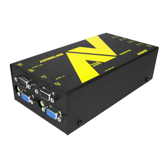
Module features Power supply connection Multi-point transmitter Link output to receiver module - link end Point to point (AV208T model pictured) Serial port connection transmitter module from source PC (AV200T model pictured) (female 9-way D-type) Indicators CATx links 5 to 8 (not AV204T) Video input... -
Page 8: Installation
Installation Locations Please consider the following important points when planning the positions of your AdderLink AV modules: • Take care not to exceed the maximum link cable lengths (please refer to the section Making cascade connections). • Ensure that the transmitters are as close as possible to the source PC system and the receivers are similarly close to the display modules. -
Page 9: Mounting
Mounting Before you begin connecting to the source PC system and display devices, it is advisable to mount the AdderLink AV modules in place. There are a number of mounting possibilities for the transmitter and receiver modules: • On a horizontal surface using the supplied self adhesive feet, •... -
Page 10: Using The Optional Rack Mount Chassis
Using the optional rack mount chassis 1 Place the optional rack plate onto the front of the transmitter or receiver module and secure it with the countersunk screws. 2 Orient the module on its side so that its labelled face is the correct way up and the securing plate is facing away from the rack. -
Page 11: Making Standard Connections
To connect video and audio from the source PC system 1 Attach a video cable of suitable type and length (fully shielded with 15 way male D-type connectors at both ends, 2m or less - Adder part number: VSC18) to the socket labelled on the AdderLink AV transmitter. - Page 12 To connect a monitor and speakers The video and audio out ports of the AdderLink AV transmitter can optionally be used either to: Connecting monitor and speakers to the AV200 transmitter • Attach a monitor and/or speakers in the vicinity of the source PC system – See below, •...
- Page 13 To connect the source computer serial port Note: The serial port feature supports RS232 serial devices at speeds up to 19200 baud and all hardware handshake lines are available (AV200T, AV200R & AV201R only). No extra error checking on the serial port signals is applied. 1 Attach the male connector of the supplied serial link cable to the socket labelled on the AdderLink AV200T transmitter or...
- Page 14 Where possible, avoid laying the CATx twisted pair link cable(s) alongside power cables. STANDARD LINK AV200 transmitters and receivers must not be connected, via a CATx link, to Adder AV100, AV101 or AV104 modules. TRANSMITTER RECEIVER Overall maximum link length: 300m Note: Long cable lengths may induce colour separation effects.
- Page 15 Connecting the power input to the AV200 transmitter to be physically identical, they are labelled as 5.3VDC (rather than the usual 5VDC). Using a standard Adder 5VDC power supply will not cause damage but may affect operation. Connecting the power input to...
-
Page 16: Connections At The Receiver
Where possible, avoid laying the CATx twisted pair link cable(s) alongside power cables. AV200 transmitters and receivers must not be connected, via a CATx link, to Adder AV100, AV101 or AV104 modules. - Page 17 Y-cable unearthed power socket or extension cable. control, a special is available (Adder part number: VSC19). 1 Attach the output connector of the power supply to the Note: The Y-cable is supported only when the AV200R/AV201R receiver is linked to an AV204T or AV208T transmitter. If the receiver is linked to an AV200T socket labelled on the AdderLink AV receiver.
-
Page 18: Making Cascade Connections
Making cascade connections Cascade connection example The AdderLink AV series of products have been specifically designed to be flexible in order to support both your immediate and future needs for media This example demonstrates the effect of cascade connections upon overall link streaming. -
Page 19: Cascading Transmitters
(Cable specification: Fully shielded with 15 way male D-type connectors at both ends, 2m or less - Adder part number: VSC18). 2 Attach a stereo audio cable between the socket labelled... -
Page 20: Switch Settings - Av204T/Av208T Only
Switch settings - AV204T/AV208T only The AdderLink AV204T and AV208T transmitter modules are both equipped Operation mode (SW1 - select before powering on) with 10-way mini switches to allow quick configuration of various items. For Normal operation normal operation in the majority of cases, all switches should be OFF. Upgrade mode Switch 1 is used when upgrading the internal firmware and switches 2 to 10 are Serial communications data byte length (SW2) -
Page 21: Operation
Operation In operation, the AdderLink AV modules are designed to be as transparent - high quality video and audio signals from the source PC system are distributed to the various display units and control signals are similarly routed back to the system. Indicator positions on AV200T, AV200R and AV201R units... -
Page 22: Serial Port Switching
ASCII console or use a utility such as the where n is the transmitter number (1, 2, 3 or 4) Adder Display Manager to provide an intuitive graphical interface. Once a switching command is issued, the network will remain fixed at that setting until... -
Page 23: Adjustments
Adjustments The AV200R and AV201R receivers both include brightness and sharpness adjustment dials. Additionally, the AV201R receiver is also equipped with two extra dials to eliminate the effects of colour skew within the video image. Brightness and sharpness adjustments The brightness and sharpness adjustments To display a suitable high contrast image provided on every AV receiver allow you to •... -
Page 24: Skew Compensation Adjustments (Av201R Only)
To display the supplied skew test pattern category 5e cables. 1 Insert the supplied Adder CD-ROM into the Skew compensation adjustments are made using two rotary dials, the first CD player of the computer. - Page 25 To zero the skew adjustment dials To adjust the skew compensation When supplied, the two skew dials are set in Your chances of achieving a successful skew compensation adjustment will be their neutral positions. i.e. no delay to either improved if you do the following: of its colours.
-
Page 26: Upgrading
Place the decompressed upgrade files onto the Windows system that will be connected (via a vacant serial port) to the Adder module. 2 Remove power from the module. 3 Connect the supplied serial cable between the port labelled on the module and a vacant serial port on the system containing the upgrade files. -
Page 27: Further Information
‘Adjustments’ section in the ‘Special Configuration’ chapter. • If not already fitted, connect a monitor to the port of the transmitter • Adder Technology website – www.adder.com module and check for a correct video image output. Check the Support section of our website for the latest solutions. -
Page 28: Safety Information
If the product should fail to operate correctly in normal use during the • Not suitable for use in hazardous or explosive environments or next to highly warranty period, Adder will replace or repair it free of charge. No liability can be flammable materials. -
Page 29: Products In The Adderlink Av200 Range
Products in the AdderLink AV200 range Cables The following items are available within the AdderLink AV200 product range: These cables are available for use when connecting the modules to systems and peripherals: • AdderLink AV200 pair (part number: ALAV200P) • Video cable - 2 metres (part number: VSC18) One AdderLink AV200T transmitter and one AdderLink AV200R receiver. -
Page 30: Emissions And Immunity
Emissions and Immunity A Category 5 (or better) twisted pair cable must be used to connect the modules in order to maintain compliance with radio frequency energy emission regulations and ensure a suitably high level of immunity to electromagnetic disturbances. All other interface cables used with this equipment must be shielded in order to maintain compliance with radio frequency energy emission regulations and ensure a suitably high level of immunity to electromagnetic disturbances. - Page 31 © 2011 Adder Technology Limited All trademarks are acknowledged. Release 1.1a May 2011 Part No. ADD0070 Adder Technology Limited, Adder Corporation, Adder Asia Pacific Technology House, 350R Merrimac Street, 6 New Industrial Road, Trafalgar Way, Bar Hill, Newburyport, Hoe Huat Industrial Building...
Need help?
Do you have a question about the AdderLink AV200 series and is the answer not in the manual?
Questions and answers