Table of Contents
Advertisement
Quick Links
Download this manual
See also:
User Manual
Advertisement
Table of Contents

Subscribe to Our Youtube Channel
Related Manuals for ADDER 2112T


Summary of Contents for ADDER 2112T
- Page 1 AdderLink Infinity 2112T User Guide ...
-
Page 2: Table Of Contents
Contents Introduction Virtual Media ................23 AdderLink ALIF 2112T unit features ...........3 What’s in the box ................4 Editing the viewer window menu bar ........25 What you may additionally need ..........5 Operation Installation Front panel indicators ...............26 Mounting ..................6 Using the VNC viewer..............27 Connections .................7... -
Page 3: Introduction
Ethernet or Fibre Optic networking. Up to sixteen remote users can log in via standard networks to view the output from the ALIF 2112T. In addition to separating one computer and its peripherals, ALIF promotes sharing. You can arrange for a limitless number of screens and speakers, distributed anywhere across the network, to receive video and audio. -
Page 4: Adderlink Alif 2112T Unit Features
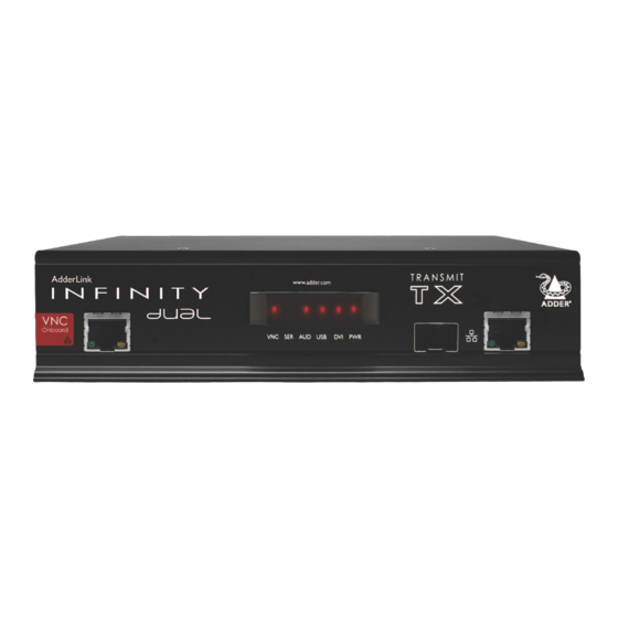
AdderLink ALIF 2112T unit features The ALIF 2112T unit is housed within a durable, metallic enclosure with most connectors situated at the rear panel - the Ethernet and fibre ports are situated on the front panel. The smart façade also features the operation indicators. -
Page 5: What's In The Box
Power adapter (20W) and country-specific power lead Combined dual link DVI-D and USB cable (1.8m) ALIF 2112T transmitter unit Four self-adhesive rubber feet Quick Start Guide Serial null modem cable 2m 2 x Audio cable 2m Single link DVI-D to DVI-D video cable... -
Page 6: What You May Additionally Need
What you may additionally need Single mode fibre module Part number: SFP-SM-LC Please refer to the table in Appendix L information about fibre modules and cables. Two 19” rack-mount brackets and four screws Part numbers: One unit per 1U rack slot: RMK4S Single link DVI-D to DVI-D video cable Two units per 1U rack slot: RMK4D Part number: VSCD1... -
Page 7: Installation
Installation Mounting There are two main mounting methods for transmitter and receiver units: • The supplied four self-adhesive rubber feet • Optional rack brackets Connections Rack brackets The optional brackets (plus four screws), allow the units to be secured within a standard rack slot. Note: The ALIF units and their power supplies generate heat when in operation and will become warm to the touch. -
Page 8: Connections
Connections Installation involves linking the ALIF 2112T (transmitter) unit to various ports on the host computer, while an ALIF RX (receiver) unit is attached to your peripherals: Click a connection to see details IMPORTANT: When using an AdderLink Infinity Management box to configure ALIF units, it is vital that all ALIF units that you wish to locate and control are set to their factory default settings. -
Page 9: Vnc Network Link
VNC network link The ALIF 2112T contains a VNC server that allows you to transmit a low-bandwidth version of the video output across standard networks to authorised remote viewers. The VNC link can either be made over the same network as the main Infinity output or via a separate one. -
Page 10: Video Link
330MHz (maximum 2560 x 2048 @ 50Hz). To make a video link 1 Wherever possible, ensure that power is disconnected from the ALIF 2112T and the host computer. 2 Connect either one or two digital video link cables to the video socket(s) on... -
Page 11: Audio Links
Audio links The audio sub-system supports two- way stereo sound via the Infinity port to ALIF receivers. However, audio is not supported via the VNC port. To make audio links 1 Connect an audio link cable between the socket on the TX unit rear panel and the speaker output socket of the host computer. -
Page 12: Usb Link
2 Connect the type A connector of the cable to a vacant USB socket on the host computer. Note: When a power switch is connected to the ALIF 2112T unit, the transmitter sends out RS232 commands to control the power switch. -
Page 13: Power In
Power in Each ALIF unit is supplied with an appropriate power adapter. When all other connections have been made, connect and switch on the power adapter unit. To apply power in 1 Attach the output lead from the power adapter to the socket on the rear panel of the unit. -
Page 14: Gigabit Network Link
ALIF units can be either connected directly to each other or via a Gigabit Ethernet network. Additionally, ALIF 2112T units can be networked by fibre optic links. For direct links over Ethernet cable, the length of cable should not exceed 100 metres (328 feet). -
Page 15: Configuration
Configuration The ALIF 2112T unit consists of two distinct sections (as detailed below) which each have their own separate configuration procedures within this chapter. The VNC port The Infinity port Uses the standard Ethernet port on the left side of the front... -
Page 16: The Infinity Port: Initial Configuration
Manual factory reset Where an ALIF TX and an ALIF RX are directly linked to each other, no A factory reset returns the ALIF 2112T unit to its default configuration. You configuration action is required, provided that they have their factory default... -
Page 17: Browser-Based Configuration Utility
To access the browser-based configuration utility network connection between the Gigabit Ethernet port of the ALIF 2112T unit 1 Temporarily connect the ALIF 2112T unit and a computer via a network, as and a computer on the same network. The configuration utility allows you to discussed opposite. -
Page 18: Performing An Upgrade
To upgrade a single unit via network link 1 Download the latest upgrade file from the Adder Technology website. In the 4 Click the ‘Firmware Upgrade’ link. Within the Firmware Upgrade page, Zip package you will find three files. -
Page 19: The Vnc Port: Initial Configuration
4 Once the file is downloaded, run it and follow the on screen instructions VNC Viewers are available for most computers, tablets and smartphones. to open a VNC connection to the ALIF 2112T. (The VNC Viewer is a single executable file which does not require an ‘installation’ step. Simply put the •... -
Page 20: Initial Configuration
IP network and use a computer located on the same network to connect to it. To perform the initial configuration admin 1 Connect the ALIF 2112T to an IP network (using the VNC port) where a 5 Enter as the Username, leave the password entry blank and click suitable computer is available on the same subnet (please see the section the OK button. -
Page 21: Controls
Controls When clicked, this button reveals a menu of options concerned with keyboard, video and mouse operation. Single Mouse Mode Mouse Control This mode is for fast network connections where the This option displays a mouse control dialogue and is useful when the remote cursor response is sufficient to provide instant visual cursor is failing to respond correctly to your mouse movements, even after using feedback on the remote screen. -
Page 22: Advanced Mouse Configuration / Info
Windows XP, Windows XP SP2, OS/2, Solaris, Solaris 9 and Mac OSX. Most of ALIF 2112T unit in order to control the mains power input into the associated these offer the Speed setting as the only option, however, the Windows Pre-Xp computer. -
Page 23: Keyboard Control / Video Settings
This option displays a keyboard control dialogue and is useful for sending This option provides a range of options related to the video configuration. keyboard combinations (to the host) that are needed regularly or that are trapped by the ALIF 2112T. Click to send Click to send... -
Page 24: Virtual Media
The Adder Virtual Media feature allows you to remotely make files available To remotely transfer files from the clipboard to a host computer that is linked to the ALIF 2112T. Disk drives, single files 1 On the remote system, log into the ALIF 2112T using the VNC viewer. - Page 25 Remotely exporting a disk drive to the host 1 On the remote system, log into the ALIF 2112T using the VNC viewer. 2 Press F8 and then V to display a Virtual Media dialogue box: Remote Drive(s) This section lists any...
-
Page 26: Editing The Viewer Window Menu Bar
Editing the viewer window menu bar If required, you can customise the menu bar of the viewer window to ensure that it contains only the necessary options. The menu bar can be edited locally by each user or edited singly by the admin or alternatively, the admin can globally alter the menu bar for all users. -
Page 27: Operation
Operation Front panel indicators In operation, many ALIF installations require no intervention once configured. Via the Infinity port, the transmitter (TX) and receiver (RX) units take care of The six front panel indicators on each unit provide a useful guide to operation: all connection control behind the scenes so that you can continue to work unhindered. -
Page 28: Using The Vnc Viewer
Options viewer because it offers more options. Click the button of the VNC viewer when entering the ALIF 2112T address during log on. Rate limit mouse events When selected, this mode greatly reduces the mouse movement data that are sent to the host computer. -
Page 29: Further Information
For technical support, use the contact form in the Support section of the • Appendix I - Known working video modes adder.com website - your regional office will then get in contact with you. Appendix J • - Hot key sequences and Adder Port Direct Appendix K •... -
Page 30: Appendix A - Configuration Menus
Appendix A Configuration menus The unit has a main configuration menu through which you can access various sub menus to configure particular items. To view the main configuration menu 1 Using VNC viewer or a browser, log on as the ‘admin’ user. 2 Click the ‘Configure’... - Page 31 This column is greyed out as this feature is not available on ALIF 2112T. Remote When ticked, the selected user can gain access via an IP network link (such as a local intranet or the wider Internet, depending on how the ALIF 2112T is connected) and/or Console Server access. Power When ticked, the selected user will be permitted to control the power input to host systems (requires optional power control switch unit(s) to be fitted).
- Page 32 Gui edit configuration To edit the menu bar locally If required, you can customise the menu bar of the viewer window to ensure 1 Login remotely via VNC viewer and display the viewer window. that it contains only the necessary options. 2 Place the mouse pointer on the menu bar and click the right mouse button.
-
Page 33: Unit Configuration
Unit configuration This page provides access to a selection of both basic and advanced settings for the ALIF 2112T. Many of the settings displayed here are also accessible through the on-screen menu. To get here 1 Using VNC viewer or a browser, log on as the ‘admin’ user. - Page 34 This option is used during calibration to account for latency delays that may be caused as signals pass through a device. During calibration, the ALIF 2112T waits for 40ms after each mouse movement before sampling the next. If a device adds a significant delay to the flow of data, the calibration process can be lengthened or may fail entirely.
- Page 35 This page allows you to configure all aspects relating to time and date within the unit. Optionally enter a recognised timezone specifier related to the current position of the ALIF 2112T unit. When an NTP server is used, the specifier will be used to provide the correct real time.
-
Page 36: Network Configuration
This is the logical link through which communications with a remote web was hard coded within your ALIF 2112T unit when it was built. It consists of six browser will be channelled. The default setting of 80 is an established standard 2-digit hexadecimal (base 16) numbers separated by colons. - Page 37 Setting IP access control To define a new IP access control entry The golden rule with this feature is ‘Include before you exclude’ or to put it 1 Click the Add button to display a popup dialogue: another way ‘Arrange allowed addresses in the list before the denied addresses’. This is because the positions of entries in the list are vitally important.
- Page 38 Serial port configuration This page allows you to configure the baud rate of the ALIF 2112T serial port that is used to control power switch devices. A full range of standard baud rates are available. Baud Rate Determines the communication speed of the OPTIONS port. The other communication settings are fixed as: No parity, 8 bit word, 1 stop bit.
- Page 39 This page provides the opportunity to configure various details for each of To create a new host entry the host systems that may be connected to the ALIF 2112T. Each entry can be 1 Click one of the host entries to reveal a Host configuration dialogue.
- Page 40 Power switching configuration Power control sequences Power switch configuration comprises two main steps: Notes: The settings given below are for Adder power switches model numbers • Configure the serial port to the same speed as used by the power OPTIONS...
- Page 41 Logging and status This screen provides various details about the user activity on the ALIF 2112T To copy and paste the log unit. You can copy the information listed within the log and paste it into another application. Date and...
-
Page 42: Appendix B - Tips For Success When Networking Alif Units
(Layer 3) respectively for 48 port L2 switches. • Cisco 4500 • HP Procurve 2910 continued • Cisco 6500 For the latest list of switches known to work with ALIF and setup instructions for them, please go to www.adder.com... - Page 43 Configuring the switches and devices The layout is vital but so too is the configuration: • Enable IGMP Snooping on all L2 switches. • Ensure that IGMP Fast-Leave is enabled on all switches with ALIF units connected directly to them. •...
-
Page 44: Appendix C Troubleshooting
Appendix C Troubleshooting Problem: The video image of the ALIF receiver shows horizontal lines Remedies: across the screen. • Ensure that IGMP snooping is enabled on all switches within the subnet. This issue is known as Blinding because the resulting video image looks as •... - Page 45 • Apple Mac with Nvidia graphics STP: When you plug the link cable from a working ALIF unit into the switch Use the Adder utility for Mac’s – Contact technical support. port, check how long it takes for the port indicator to change from orange •...
-
Page 46: Appendix D - Glossary
Appendix D Jumbo frames (Jumbo packets) IGMP Snooping Glossary The IGMP messages are effective but only operate Since its commercial introduction in 1980, the layer 2 - intended for routers to determine Ethernet standard has been successfully extended Internet Group Management Protocol whether multicast data should enter a subnet. - Page 47 Spanning Tree Protocol (STP) ALIF transmitter video settings In order to build a robust network, it is necessary Each ALIF transmitter includes controls to help you to include certain levels of redundancy within the customise how video data is transmitted. When interconnections between switches.
- Page 48 Forwarding modes In essence, the job of a layer 2 switch is to So which one to choose? The Cut-through method So why are Layer 2 and Layer 3 of particular transfer as fast as possible, data packets arriving has the least latency so is usually the best to use importance when discussing AdderLink Infinity? with AdderLink Infinity units.
-
Page 49: Appendix E - Vnc Viewer Connection Options
When ticked, ‘special’ keys (the Windows key, the Print Screen key, Alt+Tab, Adapt to network speed Alt+Escape and Ctrl+Escape) are passed directly to the ALIF 2112T rather than When ticked, VNC will automatically adjust the image quality to suit the being interpreted locally. - Page 50 When ticked, this feature reduces the mouse movement information that is sent to the ALIF 2112T and host system. This is useful for slow connections and you will notice that the remote cursor will catch up with the local cursor roughly...
- Page 51 Expert The options on this page are not The options within this section relevant to ALIF 2112T connections work correctly with ALIF 2112T in and should be left in their default their default states and should not states. require alteration except in special...
-
Page 52: Appendix F - Vnc Viewer Window Options
Used for fast network connections where a second, “predictor” cursor is not required. Ctrl, Alt, Send F8, Send Ctrl-Alt-Del Sends the selected keypress(es) to the ALIF 2112T and host computer. This is necessary because certain keys and key combinations are trapped by the VNC viewer. -
Page 53: Appendix G - Java Viewer Options
Misc • Hextile – This method offers better performance than the ZRLE when used over a high speed network because there is no need for the ALIF 2112T to Shared (don’t disconnect other viewers) spend time highly compressing the data. -
Page 54: Appendix H - The Kvmadmin Utility
• -setmodes <csv-file> For instance, the command line: kvmadmin -getconfig kvm1.cfg 192.168.2.1 ... downloads the current configuration from the ALIF 2112T unit at the given address and stores it in the local file kvm1.cfg. Whereas the command line: kvmadmin -setusers users.csv 192.168.2.1 ... -
Page 55: Appendix I - Known Working Video Modes
Appendix I Known working video modes 640x480 @ 60Hz 720x480 @ 60Hz 768x576 @ 60Hz 800x480 @ 60Hz 1024x600 @ 60Hz 1024x768 @ 60Hz 1152x768 @ 60Hz 1152x864 @ 60Hz 1280x720 @ 60Hz 1280x768 @ 60Hz 1280x800 @ 60Hz 1280x854 @ 60Hz 1280x960 @ 60Hz 1280x1024 @ 60Hz 1366x768 @ 60Hz... -
Page 56: Appendix J - Hotkey Sequences
(see ‘Using abbreviations’) Add (Plus) | Subtract (Minus) | Multiply ALIF 2112T allows you to enter commands suitable for any KVM switch in order to choose from up to 128 host systems. These switching commands can take the form Central control keys (see ‘Using abbreviations’) -
Page 57: Appendix K - General Specifications / Null-Modem Cable
Appendix K General specifications RS232 ‘null-modem’ cable pin-out Casing (w x h x d): 198mm (7.92”) x 44mm (1.76”) x 145mm (5.7”) Construction: 1U compact case, robust metal design 9pin D-type 9pin D-type Weight: 1.11kg (2.44lbs) female female Mount kits: Rack mount - single or dual units per 1U slot. -
Page 58: Appendix L - Fibre Modules And Cables
Appendix L Fibre modules and cables To suit your installation layout, two fibre modules are available for the ALIF 2112T units to suit various fibre optic cables. The specifications for all are summarised in the table below: Fibre Type Fibre size... -
Page 59: Appendix M - Magic Eye
Appendix M Magic Eye (anti-dither support added) This is enabled by default. The Magic Eye feature increases performance and reduces network traffic when the AdderLink Infinity Dual is used with Apple Macs and other host computers that have dithered video output. It also improves performance if the video source is noisy (e.g. -
Page 60: Warranty / Safety Information
• No user serviceable parts within power adapter - do not dismantle. warranty period, Adder will replace or repair it free of charge. No liability can be • Plug the power adapter into a socket outlet close to the module that it is accepted for damage due to misuse or circumstances outside Adder’s control. -
Page 61: Radio Frequency Energy
Radio Frequency Energy A Category 5 (or better) twisted pair cable must be used to connect the units in order to maintain compliance with radio frequency energy emission regulations and ensure a suitably high level of immunity to electromagnetic disturbances. All other interface cables used with this equipment must be shielded in order to maintain compliance with radio frequency energy emission regulations and ensure a suitably high level of immunity to electromagnetic disturbances. - Page 62 Web: www.adder.com www.adder.com/contact-details Contact: Support: forum.adder.com © 2013 Adder Technology Limited All trademarks are acknowledged. Documentation by: www.ctxd.com Part No. MAN-ALIF2112T • Release 1-0a...
-
Page 63: Index
Index Access control Cable spec Gateway Keyboard codes OSI model 47 null modem 42 remote setting 35 sending 22 configuration 36 Access mode Cable specifications 55 Gui editing 25 Keyboard Control 22 shared & private 21 Colour Depth 46 Keyboard layout Parts Adaptive 47 Configuration... - Page 64 Rack mounting 6 Threshold setting 22 Raw 52 Time & date configuration 34 Refresh screen 20 Troubleshooting 28,43 Remote configuration advanced unit configuration Unit Configuration 32 host configuration 38 Unit name logging and status 40 remote setting 32 network configuration 35 Upgrade setting IP access control 36 firmware 17...
Need help?
Do you have a question about the 2112T and is the answer not in the manual?
Questions and answers