Table of Contents
Advertisement
Quick Links
Download this manual
See also:
User Manual
Advertisement
Table of Contents

Subscribe to Our Youtube Channel
Related Manuals for ADDER AdderLink X-DVIPRO


Summary of Contents for ADDER AdderLink X-DVIPRO
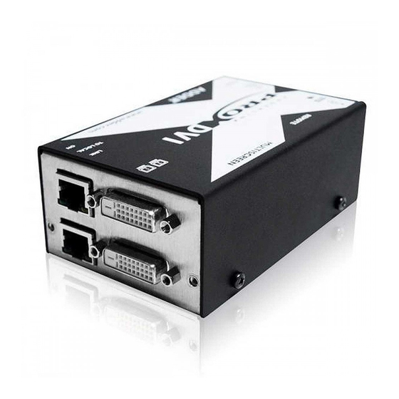
- Page 1 AdderLink X-DVIPRO Digital video and USB extenders ...
-
Page 2: Table Of Contents
Contents Welcome Operation Introduction .................2 Operation ...................10 What’s in the box ................3 General use ................10 What you may additionally need ..........4 Video display (EDID) information ........10 HDMI 1.3a operation ............10 Installation Power and activity indicators ..........10 Connections .................5 Further information Mounting the modules –... -
Page 3: Welcome
• Extensions of 55m may be achieved with single uninterrupted runs of CAT6 bulk/trunk (not patch) cable at full resolution. • Adder does not recommend CAT5e cables for use with this product. However, 45m may be typically achieved with single uninterrupted runs of CAT5e bulk/trunk (not patch) cables at full resolution. -
Page 4: What's In The Box
USB cable 2m (type A to B) Video cable DVI/D to DVI/D Eight self-adhesive rubber feet CD-ROM The MS2 variant package includes all of the above ancillary items plus: AdderLink X-DVIPRO-MS2 dual video/audio modules Local Remote 3.5mm jack to jack Additional USB cable 2m module... -
Page 5: What You May Additionally Need
What you may additionally need Power adapter and country- specific power lead for X-DVIPRO local module, if powering via the USB port is not possible. In such cases, two power adapters are required for X-DVIPRO-MS2 local modules. Part number: PSU-IEC-5VDC-2.5A Rack mount chassis Part number: X-RMK-CHASSIS Rack mount kit for X-DVIPRO... -
Page 6: Installation
Installation Connections Rack mount Installation of the X-DVIPRO and X-DVIPRO-MS2 modules is straightforward and 1 Place the rack securing plate (available as a separate kit) onto the front of the requires minimal configuration in most cases. module and secure it with the two countersunk screws. •... -
Page 7: Connections At The Local Module
Connections at the local module 1 Where possible, ensure that power is disconnected from the computer 3 Use the supplied USB cable to link the USB socket of the local module to a system to be connected. vacant USB socket on the computer. 2 Use the supplied DVI/D link cable to connect the DVI input socket of the local module to the digital video output socket of the computer. -
Page 8: Power Connection
USB connection (two USB connections in the case of the MS version). If this is not possible, then you will need to use one or two optional Adder power adapter(s). Optionally for X-DVIPRO and X-DVIPRO-MS2 units: 1 Connect the output lead of the optional power adapter(s) to the socket(s) labelled ‘... -
Page 9: Connections At The Remote Module
Connections at the remote module 1 Place the remote module adjacent to the user location. 3 Connect the leads from the keyboard and mouse to 2 Connect the DVI/D lead from the video monitor to the DVI output socket of the two USB sockets on the the remote module. -
Page 10: Power Connection
Power connection 4 Connect the link cable (see page 2 for cable advice) to the remote module socket labelled TO LOCAL 1 Connect the output lead of the supplied power adapter to the socket labelled ‘ ‘ on the remote module. POWER CATx link cable X-DVIPRO: Output lead... -
Page 11: Operation
Using optional HDMI to DVI converter cables (Adder part number: VSCD11), the Yellow: AdderLink X-DVIPRO-MS can support HDMI video and audio up to the 165MHz • On when a valid DVI video input signal is being received clock rate (1920 x 1080 at 60Hz, 24-bit colour). -
Page 12: Further Information
Troubleshooting section then we provide a number of other solutions: problem is not listed here and you cannot resolve the issue, then please refer to • Adder Technology website – www.adder.com the ‘Getting assistance’ section. Check the Support section of our website for the latest solutions and driver No video image is displayed on the remote monitor files. -
Page 13: Warranty
If the product should fail to operate correctly in normal use during the • Ensure that the twisted pair interconnect cable is installed in compliance warranty period, Adder will replace or repair it free of charge. No liability can be with all applicable wiring regulations. -
Page 14: Radio Frequency Energy
Radio Frequency Energy A Category 5 (or better) shielded twisted pair cable must be used to connect the local and remote units in order to maintain compliance with radio frequency energy emission regulations and ensure a suitably high level of immunity to electromagnetic disturbances. - Page 15 © 2011 Adder Technology Limited All trademarks are acknowledged. Release 2.0d November 2011 Part No. MAN-X-DVIPRO Adder Asia Pacific Adder Technology Limited, Adder Corporation, 6 New Industrial Road, Unit 5, Saxon Way, 350R Merrimac Street, Hoe Huat Industrial Building Newburyport,...
Need help?
Do you have a question about the AdderLink X-DVIPRO and is the answer not in the manual?
Questions and answers