Table of Contents
Advertisement
Quick Links
Inground System
REQUIRED TOOLS AND MATERIALS:
• 2 People
• Carpenter's Level
• 15' Tape Measure
• Shovel & Post Hole
Digger
• (2 each) Wrenches and/or Socket Wrenches and
• Wood Board (scrap)
• Tape
• Sawhorse or
Support Table
• Wedge
© COPYRIGHT 2005 SPALDING
Owners Manual
Customer Service Center
• N53 W24700 South Corporate Circle • Sussex, WI 53089
• Phillips Screwdriver
• Hammer
• Heavy Duty Tape
• Stepladder 8 ft. (2.4 m)
• Safety Goggles
Sockets (Deep-Well Sockets are Recommended).
7/16"
1/2"
9/16"
3/4"
• Optional: Large &
Small Adjustable
Wrenches
1/2"
9/16"
3/4"
7/16"
Toll-Free Customer Service Number for U.S: 1-800-558-5234,
For Europe: 00 800 555 85234 (Sweden: 009 555 85234),
Internet Address: http://www.huffysports.com
• U.S.A.
•
• Container to Mix
For Canada: 1-800-284-8339,
For Australia: 1-800-632 792
1
WARNING!
READ AND UNDERSTAND
OPERATOR'S MANUAL
BEFORE USING THIS UNIT.
FAILURE TO FOLLOW
OPERATING INSTRUCTIONS
COULD RESULT IN INJURY
OR DAMAGE TO PROPERTY.
12/05
ID# M881111
Advertisement
Table of Contents

Related Manuals for SPALDING M881111


Summary of Contents for SPALDING M881111
-
Page 1: Owners Manual
• Wedge 1/2" 9/16" 3/4" 7/16" Toll-Free Customer Service Number for U.S: 1-800-558-5234, For Canada: 1-800-284-8339, For Europe: 00 800 555 85234 (Sweden: 009 555 85234), For Australia: 1-800-632 792 Internet Address: http://www.huffysports.com 12/05 ID# M881111 © COPYRIGHT 2005 SPALDING... -
Page 2: Before You Start
Test-fit large bolts into large holes of elevator tubes, backboard brackets, and triangle plates. Carefully rock them in a circular motion to ream out any excess paint from holes if necessary. Not all items pictured are included with every model. ID# M881111 12/05... - Page 3 • Keep pole top covered with cap at all times. • See instruction manual for proper installation and maintenance. In the U.S.: 1-800-334-9111 In the U.S.: 1-800-558-5234 In Canada: 1-800-284-8339 In the U.S.: 1-800-558-5234 In the U.S.: 1-888-713-5488 In Canada: 1-800-284-8339 ID#: 588000 05/05 12/05 ID# M881111...
-
Page 4: Safety Instructions
TO ADJUST BACKBOARD: Backing + 1/16 Circumference 1. While holding handle, remove pin. 2. Move elevator up or down to Rolls of 500 desired height. 3. Replace pin full length to lock system at desired height. 201251 2/99 ID# M881111 12/05... - Page 5 WARRANTY CARD: Please remember to complete your product registration form either on-line at: www.huffysports.com/customer_support/product_registration or mail-in the enclosed postcard. For more information on assembly, placement, proper use, and maintenance, visit The American Basketball Council website at http://www.smarthoops.com. 12/05 ID# M881111...
- Page 6 203472 Spring, Black 203470 Washer, Flat 5/8 I.D. x 1-1/2 O.D. 203795 Nut, Special 3/8-NC 205528 Bolt, Hex-Flange 5/16-18 x 1" Long 903601 Rebar 204159 Rebar Centering Spacer * YOU MAY HAVE EXTRA PARTS WITH THIS MODEL. ID# M881111 12/05...
- Page 7 #47 (4) #42 (1) HARDWARE IDENTIFIER (NUTS & WASHERS) #27 (6) #8 (9)* #11 (4) #24 (6) #10 (4) #46 (1) #45 (1) HARDWARE IDENTIFIER (METAL SPACERS) #13 (2) * You may have extra parts with this model. 12/05 ID# M881111...
- Page 8 HARDWARE IDENTIFIER (PLASTIC SPACERS & CLIPS) #22 (4) #12 (2) #23 (4) #39 (2) HARDWARE IDENTIFIER (OTHER) #41 (1) #43 (1) #44 (1) ID# M881111 12/05...
-
Page 9: Section A: Assemble The Pole
SECTION A: ASSEMBLE THE POLE This is what your system will look like when you’ve finished this section: TOOLS REQUIRED FOR THIS SECTION CONCRETE Carpenter's Level Shovel and Post Hole Digger Container to Mix Phillips-Head Screwdriver 12/05 ID# M881111... - Page 10 Ensure ground is level with playing surface, then dig pole hole. WARNING! IMPORTANT! Maximum distance from edge of hole to edge of playing surface 6” (15.2 cm). CONTACT UTILITIES BEFORE DIGGING. XG02.EPS 18" (42.7 cm) 6" (15.2 cm) GROUND SURFACE PLAYING SURFACE 24" (61 cm) ID# M881111 12/05...
- Page 11 Snap two halves of ground sleeve (4) together. Insert and secure bottom pole section (3) into ground sleeve (4) by tightening ground sleeve cap (5). NOTE: Flared end goes inside ground sleeve. Fill hole approximately 1/3 full with mixed concrete. 12/05 ID# M881111...
- Page 12 FIG. A NOTE: Leave 1" below flange exposed for drainage hill. IMPORTANT! NOTE POSITION OF FLANGE. SIDE VIEW PLAYING SURFACE FLANGE 1" (2.54 cm) IMPORTANT! CONTINUE ON TO NEXT STEP. DO NOT WAIT FOR CONCRETE TO CURE. ID# M881111 12/05...
-
Page 13: Side View
1" (2.54 cm) NOTE: PLAYING SURFACE 1" (2.54 cm) Keep flange pushed down to concrete and leveled. SIDE VIEW IMPORTANT! WAIT A MINIMUM OF 24 HOURS BEFORE GOING ON TO NEXT STEP. CONCRETE MUST CURE. 12/05 ID# M881111 GSLV09.EPS 211121... - Page 14 (36) around the bottom area of bottom pole (see note A). NOTE A: Place top edge of anti- skid tape on mark made in step 7, NOTE A. NOTE B: Tape prevents the pole from rotating during play. IMPORTANT! KEEP GROUND SLEEVE CAP ON BOTTOM POLE. ID# M881111 12/05...
- Page 15 IMPORTANT! POLE SECTIONS SHOULD HAVE A 3-1/2" (9 CM) MINIMUM 1-1/2" 5" (3.81 cm) BOTTOM POLE OVERLAP. (12.7 cm) BOTTOM POLE Identification Sticker IMPORTANT! KEEP GROUND SLEEVE CAP ON BOTTOM POLE. Wood Scrap (NOT SUPPLIED) 12/05 ID# M881111...
- Page 16 During empty sub-freezing may tip over more if placing easily. system on sloped tank surface. In the U.S.:1-800-558-523 4 and Canada: 1-800-284-8339 201241 2/99 uppermost holes on top pole (1) - see Illustration. Wood Scrap (NOT SUPPLIED) ID# M881111 12/05...
- Page 17 Install pole mount bracket (6) and bracket reinforcement (40) with carriage bolts (7) as shown. Tighten flange nuts (8) completely. FRONT SIDE FRONT SIDE 12/05 ID# M881111...
- Page 18 (14) onto pole mount bracket (6) with carriage bolt (15) and nut (8) as shown. IMPORTANT! DO NOT OVERTIGHTEN Loop end of pin lanyard (17) over carriage bolt (15) as it passes through the pole mount bracket (6) during this assembly. ID# M881111 12/05...
- Page 19 (20), and flange nut (8) as shown. NOTE: Holes in adjustment rod allow for either rear access or side access. IMPORTANT!: Indicator labels should be applied as close to holes as possible to prevent labels from being damaged during height adjustment. 12/05 ID# M881111...
-
Page 20: Section B: Assemble The Elevator Tubes To Backboard
Toward Board Pole Upper Elevator tube Tube supérieur du dispositif élévateur / Oberes Verlängerungsrohr / Tubo elevador superior Toward Toward Board Pole Lower Elevator tube Tube inférieur du dispositif élévateur / Unteres Verlängerungsrohr / Tubo elevador inferior ID# M881111 12/05... - Page 21 Attach backboard support brackets (25) to the backboard frame using bolts (31) and nuts (10) as shown. IMPORTANT! IMPORTANT! DO NOT TIGHTEN HARDWARE COMPLETELY. IMPORTANT! NOTE ORIENTATION. 12/05 ID# M881111...
- Page 22 Attach lower elevator tubes (28) and springs (29) to backboard support brackets (25) using spacers (22), bolt (27), and nut (24) as shown. Insert T-bolt (42) into Slam Jam bracket (41) then, attach that assembly to board using bolts (47) and nuts (8). ID# M881111 12/05...
- Page 23 Attach upper elevator tubes (30) to backboard support brackets (25) using spacers (22), bolt (27), and nut (24) as shown. IMPORTANT! 12/05 ID# M881111...
-
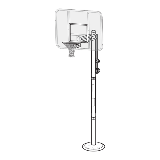
Page 24: Section C: Attach The Backboard & Elevator Assembly
SECTION C: ATTACH THE BACKBOARD & ELEVATOR ASSEMBLY TO POLE SYSTEM This is what your system will look like when you’ve finished this section: CONCRETE TOOLS REQUIRED FOR THIS SECTION Container to Mix AND/OR 3/4” (2) 3/4" Wrenches (2) Socket Wrenches and Sockets ID# M881111 12/05... - Page 25 SERIOUS INJURY AND/OR PROPERTY DAMAGE. Install handle assembly to long elevator tubes (28) using bolt (27), spacers (39), and nut (24) as shown. NOTE: Before going on to next step, adjust system assembly to the 10’ setting. 12/05 ID# M881111...
- Page 26 C • Install spring (44) onto “T” bolt (42) as shown. D • Install special nut (46) and washer (45) onto “T” bolt (42). E • Tighten nut (46) until flush with end of “T” bolt (42). ID# M881111 12/05...
- Page 27 Insert bolt (27) through left side short elevator tube (30), then stretch spring or springs (29) onto bolt (27). Insert bolt (27) through right side short elevator tube (30) and secure with nut (24). WARNING! USE EYE PROTECTION WHEN INSTALLING SPRINGS. 12/05 ID# M881111...
- Page 28 (49) near top and bottom of rebar as shown. (48) as shown. 2" 3" Reinforcement Bar Seal hole at the bottom of the bottom pole with heavy-duty tape (not included) to retain rebar and concrete inside. Tape (Not Included) ID# M881111 12/05...
- Page 29 INSTRUCTIONS WILL assembly. Allow VOID ALL WARRANTIES concrete to completely WRITTEN AND IMPLIED. cure. IMPORTANT!: WAIT A MINIMUM OF 24 HOURS BEFORE GOING ON TO NEXT STEP. CONCRETE MUST CURE. Install net (34). 12/05 ID# M881111...
-
Page 30: Section D: Upright, Secure And Use Pole System
SECTION D: UPRIGHT, SECURE AND USE POLE SYSTEM This is what your system will look like when you’ve finished this section. TOOLS REQUIRED FOR THIS SECTION Wedge Hammer ID# M881111 12/05... - Page 31 MOVE POLE ASSEMBLY INTO POSITION. THE BACKBOARD AND RIM ARE NOT LOCKED AND WILL ROTATE. FAILURE TO FOLLOW THIS WARNING COULD RESULT IN SERIOUS INJURY AND/OR PROPERTY DAMAGE. Use wedge to tap cap of ground sleeve until tight. 12/05 ID# M881111...
- Page 32 2. Move elevator up or down to desired height. 3. Replace pin full length to lock system at desired height. 201251 2/99 NOTE: Eng: Dan\Tom 1st Used: 2/99 Peel protective film from surface of acrylic backboard prior to use. ID# M881111 12/05...
Need help?
Do you have a question about the M881111 and is the answer not in the manual?
Questions and answers