Sign In
Upload
Manuals
Brands
ENCAD Manuals
Plotter
T-200
ENCAD T-200 Manuals
Manuals and User Guides for ENCAD T-200. We have
2
ENCAD T-200 manuals available for free PDF download: Service Manual
ENCAD T-200 Service Manual (162 pages)
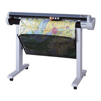
COLOR INKJET PRINTER/PLOTTERS
Brand:
ENCAD
| Category:
Printer
| Size: 3 MB
Table of Contents
Service Manual
2
User Instructions
4
Material Safety Data Sheet
6
Table of Contents
8
List of Tables
15
Chapter 1 General Description
16
Introduction
16
T-200 and T-200+ Inkjet Printer/Plotter
16
Overview
18
Related Publications
18
Electrostatic Discharge (ESD) Sensitivity
18
Warnings, Cautions and Notes
19
Printer Specifications
20
Contents of this Service Manual
21
Technical Support
23
Chapter 2 Theory of Operation
24
Introduction
24
T-200/T-200+ Printer General Block Diagram
24
General Block Diagram
25
Paper (Media) Axis Drive
26
The Carriage Axis Drive
27
Main Printed Wiring Assembly (MPWA)
28
Gate Array
29
Microprocessor
29
Flash EEPROM
30
Memory Circuits
30
Dram
31
Serial EEPROM
31
Stepper Motor Controller
32
Servo Motor Controller
34
Quadrature Signal Generation
35
Control Panel
36
Interface Circuits: Serial & Parallel
37
Carriage Assembly Circuits
38
Display Assembly
39
Power Supply
40
Chapter 3 Maintenance
41
Introduction
41
Scheduled Maintenance
41
Cleaning Procedures
42
External Cleaning
42
Slide Shaft Cleaning
42
Service Station Cleaning
43
Linear Encoder Strip Cleaning
44
Cartridge Dimples Cleaning
45
Encoder Strip Cleaning
45
Cartridge Dimple Region
45
Flex Cable Contact Cleaning
46
Flex Cable Contacts
46
Clean and Inspect Stepper Motor Gears
47
Clean and Inspect MPWA
47
Clean and Inspect Carriage Assembly
48
Reseat Connectors on MPWA and Carriage Board
48
Main PWA Connection Locations
49
Carriage PWA Connection Locations
50
Replace Carriage Bushings
51
Ribbon Connector Locking Mechanism
51
Servo Motor Winding Resistance Check
52
Stepper Motor Winding Resistance Check
53
Banding: Hardware Vs Software
54
Examples of Banding
54
Common Banding Causes
55
Alignments/Adjustments
57
Slide Shaft Profile Adjustment
57
Dial Gauge Micrometer Assembly
58
Measurement Positions for Slide Shaft
59
Slide Shaft Profile Adjustment
59
Head Height Alignment Procedure
60
Carriage Head Height Tolerance
60
Setting up Tools from Height Gauge Kit
61
Zeroing the Micrometer Gauge
61
Test Cartridge Installed
62
Paper Skew Adjustment
64
Paper Skew Adjustment Sequence
64
Pinch Roller Supports Numbering Sequence
64
Mounting Screw Information
65
Pinch Roller Support and Mounting Screws
66
Other Functional Requirements
68
Adjustment of Pinch Roller Supports
69
Visual Verification
69
Observation of Paper Skew at Rear Media Alignment Mark
70
Observation of Paper Skew at Front Media Alignment Mark
71
Adjustment of the Mounting Screws
72
Motion of Rollers and Adjustment of Mounting Screws
72
Color Calibration
73
Deadband Alignments
75
Slow Deadband
75
Color Deadband Alignment
76
Color Calibration
76
Paper Axis Test
78
Diagnostics Menu
80
Internal Cabling and Signal Flow Diagrams
83
MPWA Connections Diagram
84
Carriage PWA Connections Diagram
85
Chapter 4 Troubleshooting
86
Introduction
86
No Power
86
Initialization Failure
87
Media Does Not Move
87
Internal ERROR "Carriage Axis Failure
88
Internal ERROR "Encoder Sensor Failure
90
Internal ERROR "Paper Sensor Failure
90
Internal ERROR "MPCB Failure
91
Unrecognized Cartridges Error
91
Image Skews or Moves
91
Does Not Print
92
Ink Cartridge Misfiring
92
Paper Skewing
94
Printer Output Is Banding (Horizontal)
94
Printer Output Is Banding (Vertical)
96
Printer Output Is Banding (Horizontally and Vertically)
97
Keypad Locked-Up or Not Functioning Properly
97
Noisy Operation
98
Line Quality Degraded
99
Fan Does Not Power up
100
Media Is Not Measured Properly
100
Initialization Troubleshooting
101
Carriage Board LED D2 and D5 Locations
102
Chapter 5 Assembly\Disassembly
103
Introduction
103
Removing the Right Cover Assembly
104
Removal of Right Cover Assembly
105
Removing the MPWA Connectors
106
MPWA Connection and Screw Locations
106
Removing the MPWA
107
Removing the Right Sideplate
108
Reinstalling the Right Sideplate
109
Reinstalling the MPWA
109
Reinstalling the MPWA Connectors
109
Memory Module Removal
110
Memory Module Installation
111
Reinstalling the Right Cover Assembly
111
Removing the Left Cover
111
Reinstalling the Left Cover
112
Removing the Servo Motor
112
Removal of the Servo Motor
113
Reinstalling the Servo Motor
114
Compression of Frame Tensioner
114
Removing the Display Assembly
115
Removal of Display Assembly
115
Reinstalling the Display Assembly
116
Removing the Service Station Assembly
116
Service Station Removal
116
Reinstalling the Service Station Assembly
117
Electronics Cover Removal
118
Strain Relief Removal/Installation
119
Frame Tensioner
120
Carriage Belt Clamp
121
Carriage PWA Removal/Installation
122
Remove the Paper Sensor or the Encoder Sensor
123
Paper and Encoder Sensor Removal
124
Install the Paper Sensor or the Encoder Sensor
125
Paper and Encoder Sensor Installation
125
Replacing the Carriage Bushings
126
Carriage Bushing Removal
127
Reinstalling the Carriage Assembly, Carriage Belt and the Frame Tensioner
128
Carriage Bushing Installation
128
Removing the Trailing Cable
130
Reinstalling the Trailing Cable
131
Removing the Power Supply and ON/OFF Switch
132
Revealing the Power Supply Screws
133
Reinstalling the Power Supply and ON/OFF Switch
134
Inner Platen Parts
134
Stabilizer Bracket Removal
136
Disassembly of Plotter before Removing the Inner Platen Parts
137
Removing the Inner Platen Parts
139
Removal of Lower Drive Shaft Screws
139
Removing the Foam Block
140
Removing the Stepper Motor
141
Reinstalling the Stepper Motor
143
Reinstalling the Inner Platen Parts
143
Lower Drive Shaft Assembly and Stepper Motor Assembly
143
Reassembly of Plotter after Reinstalling the Inner Platen Parts
145
Removing the Upper Pinch Roller Supports
146
Removing the Upper Pinch Roller Support
147
Chapter 6 Parts List
150
Left Side Parts Breakdown
152
Platen and above Parts Breakdown
154
Right Side Parts Breakdown
156
Inner Platen Parts Breakdown
158
Carriage Assembly Parts Breakdown
160
Service Station Assembly Parts Breakdown
162
Advertisement
ENCAD T-200 Service Manual (163 pages)
Brand:
ENCAD
| Category:
Plotter
| Size: 7 MB
Table of Contents
Table of Contents
8
Chapter 3 Maintenance (Cont)
13
Chapter 1 General Description
16
Introduction
16
Overview
18
Related Publications
18
Electrostatic Discharge (ESD) Sensitivity
18
Warnings, Cautions and Notes
19
Printer Specifications
20
Contents of this Service Manual
21
Technical Support
23
Chapter 2 Theory of Operation
24
Introduction
24
Cadjet T-200 Printer General Block Diagram
24
Paper (Media) Axis Drive
26
The Carriage Axis Drive
27
Main Printed Wiring Assembly (MPWA)
28
Microprocessor
29
Gate Array
29
Memory Circuits
30
Flash EEPROM
30
Dram
31
Serial EEPROM
31
Stepper Motor Controller
32
Servo Motor Controller
34
Control Panel
36
Interface Circuits: Serial & Parallel
37
Carriage Assembly Circuits
38
Display Assembly
39
Power Supply
40
Fan Operation
40
Chapter 3 Maintenance
41
Introduction
41
Scheduled Maintenance
41
Cleaning Procedures
42
External Cleaning
42
Slide Shaft Cleaning
42
Service Station Cleaning
43
Linear Encoder Strip Cleaning
44
Cartridge Dimples Cleaning
45
Flex Cable Contact Cleaning
46
Clean and Inspect MPWA
47
Clean and Inspect Stepper Motor Gears
47
Clean and Inspect Carriage Assembly
48
Reseat Connectors on MPWA and Carriage Board
48
Replace Carriage Bushings
51
Servo Motor Winding Resistance Check
52
Stepper Motor Winding Resistance Check
53
Banding: Hardware Vs Software
54
Common Banding Causes
55
Alignments/Adjustments
57
Slide Shaft Profile Adjustment
57
Head Height Alignment Procedure
60
Paper Skew Adjustment
64
Paper Skew Adjustment Sequence
64
Mounting Screw Information
65
Other Functional Requirements
68
Adjustment of Pinch Roller Supports
69
Visual Verification
69
Observation of Paper Skew at Rear Media Alignment Mark
70
Observation of Paper Skew at Front Media Alignment Mark
71
Adjustment of the Mounting Screws
72
Paper Axis Calibration
73
Deadband Alignments
75
Color Deadband Alignment
76
Color Calibration
78
Diagnostics Menu
80
Clearing the NVRAM
82
Internal Cabling and Signal Flow Diagrams
84
Chapter 4 Troubleshooting
87
Introduction
87
No Power
87
Initialization Failure
88
Media Does Not Move
88
Internal ERROR "Carriage Axis Failure
89
Internal ERROR "Encoder Sensor Failure
91
Internal ERROR "Paper Sensor Failure
91
Internal ERROR "MPCB Failure
92
Unrecognized Cartridges Error
92
Image Skews or Moves
92
Does Not Print
93
Ink Cartridge Misfiring
93
Paper Skewing
95
Printer Output Is Banding (Horizontal)
95
Printer Output Is Banding (Vertical)
97
Printer Output Is Banding (Horizontally and Vertically)
98
Keypad Locked-Up or Not Functioning Properly
98
Noisy Operation
99
Line Quality Degraded
100
Fan Does Not Power up
101
Media Is Not Measured Properly
101
Initialization Troubleshooting
102
Chapter 5 Assembly\Disassembly
104
Introduction
104
Removing the Right Cover Assembly
105
Removing the MPWA Connectors
107
Removing the MPWA
108
Removing the Right Sideplate
109
Reinstalling the Right Sideplate
110
Reinstalling the MPWA
110
Reinstalling the MPWA Connectors
110
Memory Module Removal
111
Memory Module Installation
112
Reinstalling the Right Cover Assembly
112
Removing the Left Cover
112
Reinstalling the Left Cover
113
Removing the Servo Motor
113
Reinstalling the Servo Motor
115
Removing the Display Assembly
116
Reinstalling the Display Assembly
117
Removing the Service Station Assembly
117
Reinstalling the Service Station Assembly
118
Remove the Paper Sensor or the Encoder Sensor
124
Install the Paper Sensor or the Encoder Sensor
126
Replacing the Carriage Bushings
127
Reinstalling the Carriage Assembly, Carriage Belt and the Frame Tensioner
129
Removing the Trailing Cable
131
Reinstalling the Trailing Cable
132
Removing the Power Supply and ON/OFF Switch
133
Reinstalling the Power Supply and ON/OFF Switch
135
Disassembly of Plotter before Removing the Inner Platen Parts
138
Removing the Inner Platen Parts
140
Removing the Stepper Motor
142
Reinstalling the Stepper Motor
144
Reinstalling the Inner Platen Parts
144
Reassembly of Plotter after Reinstalling the Inner Platen Parts
146
Removing the Upper Pinch Roller Supports
147
Chapter 6 Parts List
151
Advertisement
Related Products
ENCAD ENCAD T200+
ENCAD Categories
Printer
All in One Printer
Plotter
More ENCAD Manuals
Login
Sign In
OR
Sign in with Facebook
Sign in with Google
Upload manual
Upload from disk
Upload from URL