
Related Manuals for Royal Sovereign RSL-2702S


Summary of Contents for Royal Sovereign RSL-2702S
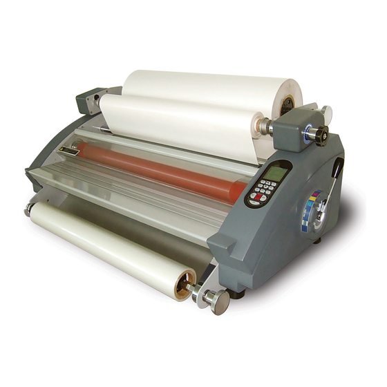
- Page 1 MODEL:RSL-2702S/RSL-382S Roll Laminator Service Manual 451-8 24B/9L,Nonhyeon-dong,Namdong-Ku,Incheon city,KOREA TEL:032) 822-0414 FAX:032)820-7105 A/S:080)262-8464 www.royalsovereign.com...
-
Page 2: Table Of Contents
Table of Content 1.Safety Precautions 3 ~ 3 ……………………………………………………………………… 2.Troubleshooting 4 ~ 10 …………………………………………………………………………… 2.1) Rollers Not Heating …………………………………………………………… 4 ~ 6 2.2) Rollers Over Heating …………………………………………………………… 6 ~ 7 2.3) Rollers Not Running ……………………………………………………………… 7 ~ 9 2.4) No Main Power …………………………………………………………………… 9 ~ 10 2.5) Poor Lamination Quality …………………………………………………………... -
Page 3: Safety Precautions
7. Ensure the unit is turned off, cooled ,and unplugged from the outlet prior to moving and/or repairing. 8. Keep out of reach of children. 9. Only Royal Sovereign authorized maintenance and service technicians should make repairs. 10. Do not attempt to laminate items that exceed total recommended material thickness for the unit. -
Page 4: Troubleshooting
2. Troubleshooting Note: While repairing: Make sure the power plug is unplugged from the power outlet. Open both side covers and rear cover. Be sure to follow the steps below in order. 2.1 Rollers Not Heating CAUSES: 1. Improper laminating mode. 2. - Page 5 3. Blown (burnt) upper and/or lower wire fuse (T/Fuse). a. Replace the T/Fuse wire located on the left-hand side. WIRE-UP-T/FUSE WIRE-LO-T/ FUSE 4. Defective Bi-Metal. a. Replace the Bi-Metal BIMETAL-L(130℃) BIMETAL-R(145℃) 5. Defective heater. a. Using the multi-meter, test the continuity of the heater. If it fails, replace the heater. Multi-meter b.
-
Page 6: Rollers Over Heating
6. Defective Main PCB. a. Replace the PCB Main. 2.2) Rollers Over Heating CAUSES 1. Lower and upper heat sensors are reversed on the PCB Main. 2. Defective T/Fuse wire. 3. Defective heater. 4. Defective main PCB. MEASURES 1. Wires for lower and upper heat sensors are reversed on the main PCB. a. -
Page 7: Rollers Not Running
3. Defective heater. a. Test continuity of the heater. If it fails, replace the heater. b. Glass tube that surrounds heating coil is broken – replace the heating element. 4. Defective Main PCB. a. Replace the PCB Main. 2.3) Rollers Not Running CAUSES 1. - Page 8 3. Opened safety cover. a. Close the safety cover and double check to insure that the safety cover switch is engaged. Note: By closing the safety cover, it engages the safety cover switch. Switch is engaged 4. Opened Front Table Switch. a.
-
Page 9: No Main Power
7. Blown motor fuse. a. Replace the motor fuse located above the main power switch. Motor Fuse 8. Defective main motor. a. Replace the main motor. 9. Defective main PCB. a. Replace the main PCB. 2.4) No Main Power CAUSES 1. - Page 10 Main Fuse 3. Disconnected main power wires. a. Check that the main power wires are properly connected. Main Power Wires 4. Transformer is defective a. Replace the transformer. Transformer...
-
Page 11: Poor Lamination Quality
2.5 Poor Lamination Quality Problem: Straight wave lines across the output. Cause: Excessive front roller pressure. Measure: Loosen the front roller pressure. Problem: Concave waves in the lamination. Cause: Excessive rear (pulling) roller pressure. Measure: Loosen the rear back roller pressure. Problem: Angled waves on both sides of the output. -
Page 12: Replacing Parts
3. Replacing Parts Note: While replacing parts: a. Make sure the power plug is unplugged from the power outlet. b. Open both side covers and rear cover. 3.1 Replacing the Right Cover. a. Take out the pressure lever (Figure 1) and four cover screws using Phillips screw driver (Figure 2). Figure 2 Figure 1 b. -
Page 13: Figure
3.3 Replacing Rear Cover a. Take off the left and right covers. b. Take out the four screws from frames,two screws of each side(Figure 5,Figure 6) Figure 5 Figure 3.4 Replacing the Main PCB a. Remove the rear cover and label all the wires before unplugging from the Main PCB. b. -
Page 14: Figure
c. Take out the broken heater. Figure 11 Figure 11 Note: a. When inserting the heater into the roller, rotate the heater slightly and push the rod in gently. b. Use an air blower to blow out the broken pieces of heating rod. (Please ensure that no one is standing on the other side.) 3.7 Replacing the Cross Cutter a. -
Page 15: Adjustments
4. Adjustments 4.1 Adjusting Take-up Shaft Speed CAUSES: 1.Main rollers and take-up shaft speed is not synchronized. MEASURES: Adjust take-up shaft speed,by loosenning or tightenning the knob According to label-take up. C.W – Tighten. C.C.W – Lossen. C.C.W 4.2 Adjusting front and rear rollers Pressure •... - Page 16 4.Laminating Test – Laminate samples with different thickness of substrates. 5.Check above steps 2 through 4 with 3mil & 5mil films. Figure C...
-
Page 17: Parts List
5. Part list RSL-2702S Part list RSL-2702S Part No. Part Name Remark 013LR2012F FRAME-SENSOR 013LR2087A FRAME-L 013LR2088A FRAME-R 013LR3002K FRAME-CUTTER 013LR3009A FRAME-REAR 013LR3021A PLATE-MIDDLE 013LR3075A BASE-FRONT 013LR3076A BASE-REAR 013LR4004A FRAME-COVER SAFETY 014LR3001A TABLE-FRONT 015LR2001B IDLE BAR LOW 015LR3011A IDLE-BAR 015LR3012A... - Page 18 RSL-2702S 122LR4050A BUSH-ROLLER LAMI,LO-RIGHT ASS'Y 124LR4005A 124LR4006A 1"CORE 125LR4001A HANDLE-TENSION 125LR4003B LEVER-PRESSURE 125LR4004A SHAFT-TENSION 2 125LR4008A SUPPORT-SPRING 131LR4017A SPROCKET-LAMI 131LR4022B SPROCKET-DOUBLE 131LR4023A SPROCKET-TAKE UP 131LR4034A SPROCKET-MOTOR 133LR2021A ROLLER-LAMI,LO 133LR2021B ROLLER-LAMI,UP 133LR2022A ROLLER-PULL,LO 133LR2022B ROLLER-PULL,UP 134LR4001A PULLEY-CHAIN 134LR4003A BUSH-PULLEY 136LR4001C CHAIN...
- Page 19 RSL-2702S 23200X002A SUPPORT-PCB 23300X001A BUSHING-CORD 32500X0005 FUSE-MAIN 104-1 32500X0008 FUSE-MAIN 34000S011A POWER TRANSFORMER 350LR3022A PCB-SUB ASS'Y 350LR3036C PCB-MAIN ASS'Y 363LP3001A BI-METAL LO 363LR4001F BI-METAL UP 36400X002B SWITCH-MAIN 36400X014B MICRO S/W 36600X001A FUSE-HOLDER 380CR4003A POWER CORD 113-1 380CR4004A POWER CORD 113-2...
-
Page 20: Exploded Drawings
5. Part list RSL-382S Part list RSL-382S Part No. Part Name Remark 013LR2012G FRAME-SENSOR 013LR2087A FRAME-L 013LR2088A FRAME-R 013LR3002H FRAME-CUTTER 013LR3035A FRAME-REAR 013LR3036A PLATE-MIDDLE 013LR3069A BASE-FRONT 013LR3070A BASE-REAR 013LR4004A FRAME-COVER SAFETY 014LR3001B TABLE-FRONT 015LR2010A IDLE BAR LOW 015LR3011B IDLE-BAR 015LR3012B SHAFT-DECURLING 021CR3001A KNOB-CUTTER,C... - Page 21 RSL-382S 122LR4050A BUSH-ROLLER LAMI,LO-RIGHT ASS'Y 124LR4005A 124LR4006A 1"CORE 125LR4001A HANDLE-TENSION 125LR4003B LEVER-PRESSURE 125LR4004A SHAFT-TENSION 2 125LR4008A SUPPORT-SPRING 131LR4017A SPROCKET-LAMI 131LR4022B SPROCKET-DOUBLE 131LR4023A SPROCKET-TAKE UP 131LR4034A SPROCKET-MOTOR 133LR3001A ROLLER-LAMI 133LR3002A ROLLER-PULL 134LR4001A PULLEY-CHAIN 134LR4003A BUSH-PULLEY 136LR4001C CHAIN 136LR4001G CHAIN-2(TAKE UP) 138LR4001A SPRING-CUTTER CROSS 138LR4012A SPRING-TENSION...
- Page 22 RSL-382S 033LR4002A WASHER-BI METAL 36400X002B SWITCH-MAIN 36400X014B MICRO S/W 36600X001A FUSE-HOLDER 380LR4001A POWER CORD 113-1 380LR4003A POWER CORD 113-2 380LR4007A POWER CORD 381LR4013J WIRE-POWER S/W 381LR4020B WIRE-FUSE,EU 381LR4030D WIRE-UP HEATER1,EU 381LR4044B WIRE-MAIN 381LR4052A WIRE-MOTOR 381LR4054A WIRE-LO HEATER2,EU 381LR4055A WIRE-UP HEATER2,EU 381LR4084A WIRE-T/FUSE(UP) 381LR4091A...
- Page 23 6. Explode View Explode View Frame L Frame R Frame, Roller and Other View Wire, Front Table ,Film Shaft and Control PCB...
- Page 24 RSL-2702S Expolde View 013LR2012F FRAME-SENSOR 013LR2087A FRAME-L 013LR2088A FRAME-R 013LR3002K FRAME-CUTTER 013LR3009A FRAME-REAR 013LR3021A PLATE-MIDDLE 013LR3075A BASE-FRONT 013LR3076A BASE-REAR 013LR4004A FRAME-COVER SAFETY 014LR3001A TABLE-FRONT 015LR2001B IDLE BAR LOW 015LR3011A IDLE-BAR 015LR3012A SHAFT-DECURLING 021CR3001A KNOB-CUTTER,C 021LR0001A COVER-L 021LR2008A COVER-TAKE UP,L 021LR2013A COVER-TAKE UP,R...
- Page 25 Frame - L 013LR2087A FRAME-L 021LR0001A COVER-L 021LR2008A COVER-TAKE UP,L 021LR4001A LIMIT SWITCH COVER 026LR4006A FOOT 112004001D NUT 12200X009A DU BUSH 12200X028A DU BUSH 122LR4024A BUSH-ROLLER LAMI,UP 124LR4005A CAM 138LR4015A SPRING-PRESSURE 141LP4018A BRACKET-T/FUSE 141LR3017A PLATE-PRESSURE,L 141LR4035A PLATE-DU BUSH 141LR4054A BRACKET-LIMIT SWITCH 141LR4060A PLATE-PRESSURE,LAMI 141LR4061A PLATE-PRESSURE,PULL 141LR4081A...
-
Page 26: Wire Diagram
Frame - R 013LR2088A FRAME-R 021LR2013A COVER-TAKE UP,R 021LR3018A COVER-R 023LR3005A BUTTON-FUNC 023LR4004A KNOB-TENSION 023LR4007A KNOB-LEVEL 026LR4006A FOOT 12200X005A BEARING-TRUST NEEDLE 12200X022A BEARING-RADIAL TRUST 12200X028A DU BUSH 122LR4024A BUSH-ROLLER LAMI,UP 124LR4005A CAM 125LR4001A HANDLE-TENSION 125LR4003B LEVER-PRESSURE 125LR4004A SHAFT-TENSION 2 125LR4008A SUPPORT-SPRING 131LR4017A SPROCKET-LAMI 131LR4022B SPROCKET-DOUBLE 131LR4023A SPROCKET-TAKE UP... - Page 27 Frame, Roller and Other View 013LR2012F FRAME-SENSOR 013LR2087A FRAME-L 013LR2088A FRAME-R 013LR3002K FRAME-CUTTER 013LR3009A FRAME-REAR 013LR3021A PLATE-MIDDLE 013LR3075A BASE-FRONT 013LR3076A BASE-REAR 013LR4004A FRAME-COVER SAFETY 014LR3001A TABLE-FRONT 015LR2001B IDLE BAR LOW 015LR3011A IDLE-BAR 015LR3012A SHAFT-DECURLING 021CR3001A KNOB-CUTTER,C ASMLR1602A ASM-SENSOR ASMLR1608A ASM-SENSOR 021LR3024B COVER-SAFETY 023LR4002A KNOB-BOLT GUIDE 026LR4006A FOOT...
- Page 28 Wire, Film Shaft,Ass'y-Auto 111LR4004A BOLT-CORE 120LR4014A SHAFT-TAKE UP 12200X034A DU BUSH 124LR4006A 1"CORE 380CR4003A POWER CORD 113-1 380CR4004A POWER CORD 113-2 380LR4001A POWER CORD 113-3 380LR4001B POWER CORD 113-4 380LR4003A POWER CORD 113-5 380LR4007A POWER CORD 381LR4013C WIRE-POWER S/W 381LR4020B WIRE-FUSE,EU 381LR4030D WIRE-UP HEATER1,EU 381LR4043A WIRE-SAFETY S/W 381LR4044A WIRE-MAIN...
- Page 29 RSL-382S Expolde View 013LR2012G FRAME-SENSOR 013LR2087A FRAME-L 013LR2088A FRAME-R 013LR3002H FRAME-CUTTER 013LR3035A FRAME-REAR 013LR3036A PLATE-MIDDLE 013LR3069A BASE-FRONT 013LR3070A BASE-REAR 013LR4004A FRAME-COVER SAFETY 014LR3001B TABLE-FRONT 015LR2010A IDLE BAR LOW 015LR3011B IDLE-BAR 015LR3012B SHAFT-DECURLING 021CR3001A KNOB-CUTTER,C 021LR0001A COVER-L 021LR2008A COVER-TAKE UP,L 021LR2013A COVER-TAKE UP,R ASMLR1604A ASM-SENSOR ASMLR1608A ASM-SENSOR 021LR3018A COVER-R...
-
Page 30: Backup
Frame - L 013LR2087A FRAME-L 021LR0001A COVER-L 021LR2008A COVER-TAKE UP,L 021LR4001A LIMIT SWITCH COVER 026LR4006A FOOT 112004001D NUT 12200X009A DU BUSH 12200X028A DU BUSH 122LR4024A BUSH-ROLLER LAMI,UP 124LR4005A CAM 138LR4015A SPRING-PRESSURE 141LP4018A BRACKET-T/FUSE 141LR3017A PLATE-PRESSURE,L 141LR4035A PLATE-DU BUSH 141LR4054A BRACKET-LIMIT SWITCH 141LR4060A PLATE-PRESSURE,LAMI 141LR4061A PLATE-PRESSURE,PULL 141LR4081A BRACKET-HEATER,LO-L... - Page 31 Frame - R 013LR2088A FRAME-R 021LR2013A COVER-TAKE UP,R 021LR3018A COVER-R 023LR3005A BUTTON-FUNC 023LR4004A KNOB-TENSION 023LR4010A KNOB-LEVEL 026LR4006A FOOT 12200X005A BEARING-TRUST NEEDLE 12200X022A BEARING-RADIAL TRUST 12200X028A DU BUSH 122LR4024A BUSH-ROLLER LAMI,UP 124LR4005A 125LR4001A HANDLE-TENSION 125LR4003B LEVER-PRESSURE 125LR4004A SHAFT-TENSION 2 125LR4008A SUPPORT-SPRING 131LR4017A SPROCKET-LAMI 131LR4022B...
- Page 32 Frame, Roller and Other View 013LR2012G FRAME-SENSOR 013LR2087A FRAME-L 013LR2088A FRAME-R 013LR3002H FRAME-CUTTER 013LR3035A FRAME-REAR 013LR3036A PLATE-MIDDLE 013LR3069A BASE-FRONT 013LR3070A BASE-REAR 013LR4004A FRAME-COVER SAFETY 014LR3001B TABLE-FRONT 015LR2010A IDLE BAR LOW 015LR3011B IDLE-BAR 015LR3012B SHAFT-DECURLING 021CR3001A KNOB-CUTTER,C ASMLR1604A ASM-SENSOR ASMLR1608A ASM-SENSOR 021LR3024A COVER-SAFETY 023LR4002A KNOB-BOLT GUIDE 026LR4006A FOOT...
- Page 33 Wire, Front Table, Film Shaft 111LR4004A BOLT-CORE 120LR4014C SHAFT-TAKE UP 12200X034A DU BUSH 124LR4006A 1"CORE 380LR4001A POWER CORD 113-1 380LR4003A POWER CORD 113-2 380LR4007A POWER CORD 381LR4013J WIRE-POWER S/W 381LR4020B WIRE-FUSE,EU 381LR4030D WIRE-UP HEATER1,EU 381LR4044B WIRE-MAIN 381LR4052A WIRE-MOTOR 381LR4054A WIRE-LO HEATER2,EU 381LR4055A WIRE-UP HEATER2,EU 381LR4084A...
- Page 34 7. RSL-2702S,RSL-382S Wire Diagram...
- Page 35 ③ ② ① ⑨ ④ ⑧ ⑦ ⑩ ⑥ ⑤ <Connect part> 1. Wire Main. 6. Wire Up Heater. 2. Wire Sensor Up 7. Wire Fan(2EA) 3. Wire Sensor Low 8. Wire Power Transformer In 4. Wire Power 9. Motor wires 5.
- Page 36 <SUB PCB and Frame-R Heater Layout> Wire Up Heater Bimetal(145℃) Wire Up Sensor Power Cord Wire Bimetal Fuse Main Wire Lo Heater SUB PCB Motor Power cord Wire-Fuse Wire power...
- Page 37 <MICRO SWITCH and Frame-L Heater Layout> Wire F/Fuse (133℃) Wire Motor Wire Safety S/W Bimetal (130℃) Wire F/Fuse (133℃) Wire Bimetal Safety Cover Micro S/W Front Table Micro S/W...
Need help?
Do you have a question about the RSL-2702S and is the answer not in the manual?
Questions and answers