
Related Manuals for Fujitsu MS-6191


Summary of Contents for Fujitsu MS-6191
-
Page 1: User Manual
Mainboard MS-6191 User manual MS-6191 Version 1.0 Manual Rev: 1.0 Release Date: October 1999... - Page 2 Shielded interface cables and A.C. power cord, if any, must be used in order to comply with the emission limits. VOIR LA NOTICE D'INSTALLATION AVANT DE RACCORDER AU RESEAU. Micro-Star International MS-6191 Tested to comply with FCC Standard For Home or Office Use...
- Page 3 Mainboard MS-6191 Edition October 1999 Copyright Notice The material in this document is the intellectual property of MICRO- STAR INTERNATIONAL. We take every care in the preparation of this document, but no guarantee is given as to the correctness of its contents.
- Page 4 Mainboard MS-6191 Safety Instructions 1. Always read the safety instructions carefully. 2. Keep this User’s Manual for future reference. 3. Keep this equipment away from humidity. 4. Lay this equipment on a reliable flat surface before setting it up. 5. The openings on the enclosure are for air convection hence protects the equipment from overheating.
- Page 5 756 peripheral bus controllers feature an integrated ISA bus controller, an enhanced IDE controller with Ultra DMA-66 support, and a keyboard/mouse controller. THe MS-6191 ATX IR2 mainboard is one of our system board to implement the AMD-750 chipset (AMD-751 and AMD-756), which supports a single Slot A for AMD Athlon ®...
- Page 6 Mainboard MS-6191 1.1 Mainboard Features Slot A for AMD Athlon processor. ® Support 500MHz, 550MHz, 600MHz, or higher processor Chipset ® Irongate chipset. (Northbridge) - 200MHz EV6 System Interface speed - 100MHz SDRAM - 1x/2x AGp - Status - Silicon currently in bring-up ®...
- Page 7 Mainboard MS-6191 On-Board IDE An IDE controller on the AMD Viper chipset provides IDE ® HDD/CD-ROM with PIOand Ultra DMA/66 operation modes. Can connect up to four IDE devices. On-Board Peripherals On-Board Peripherals include: - 1 floppy port supports 2 FDD with 360K, 720K, 1.2M, 1.44M 2.88Mbytes.
-
Page 8: Mainboard Layout
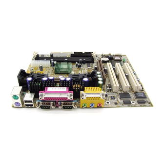
Mainboard MS-6191 1.2 Mainboard Layout T: Mouse B: Keyboard Ports AMD-751 chipset AGP Slot BATT JSLP1 PCI Slot 1 Creative USB2 ES1373 PCI Slot 2 VT82C596 PCI Slot 3 JWOL JBAT1 JFP1 JMODEM MS-6191 MICRO ATX IR2 Mainboard... -
Page 9: Hardware Installation
Mainboard MS-6191 Chapter 2 HARDWARE INSTALLATION 2.1 Central Processing Unit: CPU 2.1-1 CPU Installation Procedures Step 1: Install the Retention Mechanism. Attach the Retention Mechanism to the Mainboard. Push the Plastic lock to secure the Retention Mechanism into the mainboard. -
Page 10: Cpu Core Speed Derivation Procedure
Mainboard MS-6191 2.1-2 CPU Core Speed Derivation Procedure The Mainboard can auto-detect the processor speed. Just insert the AMD Athlon processor into Slot A. CPU Clock 100MHz Core/Bus ratio then CPU core speed Host Clock x Core/Bus ratio 100MHz x 5... - Page 11 Mainboard MS-6191 2.1-4 Fan Power Connectors: J9, J12, and J6 These connectors support system-cooling fan with +12V. It supports three pin head connector. When connecting the wire to the connector, always take note that the red wire is the positive and should be connected to the +12V, the black wire is ground and should be connected to GND.
-
Page 12: Clear Cmos Jumper: Jbat1
Mainboard MS-6191 2.2 Clear CMOS Jumper: JBAT1 A battery must be used to retain the mainboard configuration in CMOS RAM. Short 1-2 pins of JBAT1 to store the CMOS data. JBAT1 Keep Data Clear Data Note: You can clear CMOS by shorting 2-3 pin, while the system is off. - Page 13 Mainboard MS-6191 2.3 Memory Installation 2.3-1 Memory Bank Configuration The mainboard supports a maximum memory size of 768MB for SDRAM: It provides two 168-pin unbuffered DIMMs (Double In-Line Memory Module) sockets. It supports 8 MB to 256 Mbytes DIMM memory module.
- Page 14 Mainboard MS-6191 2.3-2 Memory Installation Procedures A. How to install a DIMM Module Single Sided DIMM Double Sided DIMM 1. The DIMM slot has a two Notch Key “VOLT and DRAM”, so the DIMM memory module can only fit in one direction.
-
Page 15: Memory Population Rules
Mainboard MS-6191 3. The plastic clip at the side of the DIMM slot will automatically close. 2.3-3 Memory Population Rules 1. Supports only PC100 SDRAM DIMM. 2. To operate properly, at least one 168-pin DIMM module must be installed. 3. This mainboard supports Table Free memory, so memory can be installed on DIMM1 or DIMM 2 in any order. -
Page 16: Case Connector: Jfp1
Mainboard MS-6191 2.4 Case Connector: JFP1 The Power Switch, Reset Switch, Power LED, Speaker, Keylock and HDD LED are all connected to the JFP1 connector block. Keylock HDD LED Dual Power Color Switch Speaker Power Switch Reset Switch JFP1... -
Page 17: Power Switch
Mainboard MS-6191 2.4-1 Power Switch Connect to a 2-pin push button switch. This switch has the same feature with JRMS1. 2.4-2 Reset Switch Reset switch is used to reboot the system rather than turning the power ON/OFF. Avoid rebooting while the HDD LED is lit. You can connect the Reset switch from the system case to this pin. -
Page 18: Floppy Disk Connector: Fdd
Mainboard MS-6191 2.5 Floppy Disk Connector: FDD The mainboard also provides a standard floppy disk connector FDD that supports 360K, 720K, 1.2M, 1.44M and 2.88M floppy disk types. This connector supports the provided floppy drive ribbon cables. -
Page 19: Hard Disk Connectors: Ide1 & Ide2
Mainboard MS-6191 2.6 Hard Disk Connectors: IDE1 & IDE2 The mainboard has a 32-bit Enhanced PCI IDE Controller that provides PIO mode 0~4, Bus Master, and Ultra DMA/33/66 function. It has two HDD connectors IDE1 (primary) and IDE2 (secondary). You can connect up to four hard disk drives, CD-ROM, 120MB Floppy (reserved for future BIOS) and other devices to IDE1 and IDE2. -
Page 20: Power Supply
Mainboard MS-6191 2.7 Power Supply 2.7-1 ATX 20-pin Power Connector: JPWR1 This connector supports the power button on-board. Using the ATX power supply, functions such as Modem Ring Wake-Up and Soft Power Off are supported by this mainboard. This power connector supports instant power on function which means that system will boot up instantly when the power connector is inserted on the board. -
Page 21: Irda Infrared Module Connector: Ir
Mainboard MS-6191 Warning: Since the mainboard has the instant power on function, make sure that all components are installed properly before inserting the power connector to ensure that no damage will be done. 2.8 IrDA Infrared Module Connector: IR The mainboard provides one 5-pin infrared (IR) connector for IR modules. -
Page 22: Pin Definition
Mainboard MS-6191 2.9 Serial Port Connectors: COM 1 and COM 2 The mainboard has two 9-pin male DIN connectors for serial port COM 1 and COM 2. These ports are 16550A high speed communication port that send/receive 16 bytes FIFOs. You can attach a mouse or a modem cable directly into this connector. -
Page 23: Parallel Port Connector: Lpt1
Mainboard MS-6191 2.10 Parallel Port Connector: LPT1 The mainboard provides a 25 pin female centronic connector for LPT. A parallel port is a standard printer port that also supports Enhanced Parallel Port(EPP) and Extended capabilities Parallel Port(ECP). See connector and... -
Page 24: Mouse Connector: Jkbms1
Mainboard MS-6191 SELECT 2.11 Mouse Connector: JKBMS1 The mainboard provides a standard PS/2 ® mouse mini DIN connector for attaching a PS/2 mouse. You can plug a PS/2 mouse directly into this ® ® connector. The connector location and pin definition are shown below:... -
Page 25: Joystick/Midi Connectors
Mainboard MS-6191 2.13 Joystick/Midi Connectors You can connect joystick or game pads to this connector. Joystick/MIDI 2.14 Audio Port Connectors Line Out is a connector for Speakers or Headphones. Line In is used for external CD player, Tape layer, or other audio devices. Mic is a connector for the microphones. -
Page 26: Usb Connectors
Mainboard MS-6191 2.15 USB Connectors The mainboard provides a UHCI(Universal Host Controller Interface) Universal Serial Bus root for attaching USB devices like: keyboard, mouse and other USB devices. You can plug the USB device directly to this connector. USB Port 2... - Page 27 Mainboard MS-6191 2.16 USB Front Connector The mainboard provides a front Universal Serial Bus connector. This is an optional USB connector for Front Panel. USB2...
- Page 28 Mainboard MS-6191 2.17 Wake-Up on LAN Connector: JWOL The JWOL connector is for use with LAN add-on cards that supports Wake Up on LAN function. To use this function, you need to set the “Wake-Up on Lan” to enable at the BIOS Power Management Setup.
-
Page 29: Power Saving Switch Connector: Jslp1
Mainboard MS-6191 2.18 Power Saving Switch Connector: JSLP1 Attach a power saving switch to JSLP1. When the switch is pressed, the system immediately goes into suspend mode. Press any key and the system wakes up. JSLP1... - Page 30 Mainboard MS-6191 2.19 Modem Wake Up Connector: JMODEM The JMODEM connector is for use with Modem add-on card that supports the Modem Wake Up function. To use this function, you need to set the “Modem Ring Resume” to enable at the BIOS Power Management Setup.
- Page 31 Mainboard MS-6191 Note: To be able to use this function, you need a power supply that provide enough power for this feature. (750 ma power supply with 5V Stand-by) 2.20 Modem-In: J16 The connector is for Modem with internal voice connector.
- Page 32 Mainboard MS-6191 2.21 AUX Line In Connector: J15 This connector is used for DVD Add on Card with Line In connector.
- Page 33 Mainboard MS-6191 2.22 CD-In Modem Connector: J14 This connector is for CD-ROM voice connector.
-
Page 34: Award Bios Setup
Mainboard MS-6191 Chapter 3 ® AWARD BIOS SETUP Award ® BIOS ROM has a built-in Setup program that allows users to modify the basic system configuration. This type of information is stored in battery-backed RAM (CMOS RAM), so that it retains the Setup information when the power is... -
Page 35: Entering Setup
Mainboard MS-6191 3.1 Entering Setup Power on the computer and press <Del> immediately to allow you to enter Setup. The other way to enter Setup is to power on the computer. When the below message appears briefly at the bottom of the screen during the POST (Power On Self Test), press <Del>... -
Page 36: The Main Menu
Mainboard MS-6191 3.3 The Main Menu Once you enter Award ® BIOS CMOS Setup Utility, the Main Menu (Figure 1) will appear on the screen. The Main Menu allows you to select from ten setup functions and two exit choices. Use arrow keys to select among the items and press <Enter>... - Page 37 Mainboard MS-6191 Save & Exit Setup Save CMOS value changes to CMOS and exit setup. Exit Without Saving Abandon all CMOS value changes and exit setup.
-
Page 38: Standard Cmos Features
Mainboard MS-6191 3.4 Standard CMOS Features The items in Standard CMOS Setup Menu are divided into 10 categories. Each category includes no, one or more than one setup items. Use the arrow keys to highlight the item and then use the <PgUp> or <PgDn> keys to select the value you want in each item. - Page 39 Mainboard MS-6191 Access Mode The settings are Auto, Normal, Large,LBA. Cylinder number of cylinders Head number of heads Precomp write precom Landing Zone landing zone Sector number of sectors...
-
Page 40: Advanced Bios Features
Mainboard MS-6191 3.5 Advanced BIOS Features CMOS Setup Utility - Copyright(C) 1984-1999 Award Software Advanced BIOS Features Item Help Virus Warning Disabled CPU Internal Cache Enabled External Cache Enabled Menu Level Quick Power On Self Test Enabled First Boot Device... - Page 41 Mainboard MS-6191 CPU Internal Cache The default value is Enabled. Enabled (default) Enable cache Disabled Disable cache Note: The internal cache is built in the processor. External Cache Choose Enabled or Disabled. This option enables the level 2 cache memory.
-
Page 42: Security Option
Mainboard MS-6191 Security Option This category allows you to limit access to the system and Setup, or just to Setup. System The system will not boot and access to Setup will be denied if the correct password is not entered at the prompt. -
Page 43: Advanced Chipset Features
Mainboard MS-6191 3.6 Advanced Chipset Features The Chipset Features Setup option is used to change the values of the chipset registers. These registers control most of the system options in the computer. Choose the “Advanced Chipset Features” from the Main Menu and the following screen will appear. - Page 44 Mainboard MS-6191 System BIOS Cacheable Selecting Enabled allows caching of the system BIOS ROM at F0000h-FFFFFh, resulting in better system performance. However, if any program writes to this memory area, a system error may result. The settings are: Enabled and Disabled.
- Page 45 Mainboard MS-6191 SDRAM PH Limit This item specifies the number of consecutive Page-Hit requests to allow before choosing a non Page-Hit request. The settings are: 1/4/32/64 cycles. SDRAM Idle Limit This item specify the number of idel cycles to wait before precharging an idle bank. The settings are: 1/8/32/64 cycles.
-
Page 46: Integrated Peripherals
Mainboard MS-6191 3.7 Integrated Peripherals CMOS Setup Utility - Copyright(C) 1984-1999 Award Software Integrated Peripherals IDE Read/Write Prefetch Disabled IDE Primary Master PIO Auto Item Help IDE Primary Slave PIO Auto IDE Secondary Master PIO Auto IDE Secondary Slave PIO Auto Menu Level >... - Page 47 Mainboard MS-6191 Select Enabled if your system contains a Universal Serial Bus (USB) controller and you have a USB keyboard. The settings are: Enabled, Disabled. Init Display First This item allows you to decide to activate whether PCI Slot or AGB first. The settings are: PCI Slot, AGB Onboard Audio Device Select Enabled if your system has a onboard Audio controller installed on the system board and you wish to use it.
-
Page 48: Power Status Led
Mainboard MS-6191 To operate the onboard parallel port as Standard Parallel Port only, choose “SPP.” To operate the onboard parallel port in the EPP modes simultaneously, choose “EPP.” By choosing “ECP”, the onboard parallel port will operate in ECP mode only. Choosing “ECP + EPP” will allow the onboard parallel port to support both the ECP and EPP modes simultaneously. -
Page 49: Power Management Setup
Mainboard MS-6191 3.8 Power Management Setup The Power Management Setup allows you to configure you system to most effectively save energy while operating in a manner consistent with your own style of computer use. CMOS Setup Utility - Copyright(C) 1984-1999 Award Software... -
Page 50: Reload Global Timer Events
Mainboard MS-6191 Suspend Type Select the Suspend Type. The settings are: PWRON Suspend, Stop Grant. Standby Mode When enabled and after the set time of system inactivity, all devices except will be shut off. The settings are: 1/2/4/8/12/20/30/40 Min, 1 Hour, and Disabled. - Page 51 Mainboard MS-6191 Secondary IDE 1 Parallel Port Serial Port IRQ3 (COM 2) IRQ4 (COM 1) IRQ5 (LPT 2) IRQ6 (Floppy Disk) IRQ7 (LPT 1) IRQ8 (RTC Alarm) IRQ9 (IRQ2 Redir) IRQ10 (Reserved) IRQ11 (Reserved) IRQ12 (PS/2 Mouse) IRQ13 (Coprocessor) IRQ14 (Hard Disk)
-
Page 52: Pnp/Pci Configurations
Mainboard MS-6191 3.9 PnP/PCI Configurations This section describes configuring the PCI bus system. PCI, or Personal Computer Interconnect, is a system which allows I/O devices to operate at speeds nearing the speed the CPU itself uses when communicating with its own special components. -
Page 53: Load Fail-Safe/Optimized Defaults
Mainboard MS-6191 3.10 Load Fail-Safe/Optimized Defaults Load Fail-Safe Defaults When you press <Enter> on this item, you get a confirmation dialog box with a message similar to: Load Fail-Safe Defaults (Y/N) ? N Pressing ‘Y’ loads the BIOS default values for the most stable, minimal-performance system operations. -
Page 54: Set Supervisor/User Password
Mainboard MS-6191 3.11 Set Supervisor/User Password You can set either supervisor or user password, or both of them. The differences are: Supervisor password : can enter and change the options of the setup menus. User password Can only enter but do not have the right to change the options of the setup menus. When you select this function, the following message will appear at the center of the screen to assist you in creating a password. - Page 55 Mainboard MS-6191 Chapter 4 ® CREATIVE AUDIO DRIVER 1. Overview The Creative ® ES1373 digital controller provides the next generation of audio performance to the PC market. 1.1 Features SoundScape WaveTable Synthesizer. Full DOS Game Compatibility. PCI Bus Master for fast DMA.
- Page 56 Mainboard MS-6191 2. Creative Audio Driver 2. Audio Driver Setup & Usage Procedures Insert the CD-title into your CD-ROM drive. This CD will auto-run. This will display installation for VGA driver and sound driver. Just click the button for automatic installation for audio driver.
Need help?
Do you have a question about the MS-6191 and is the answer not in the manual?
Questions and answers