
Subscribe to Our Youtube Channel
Related Manuals for Fujitsu MB96300


Summary of Contents for Fujitsu MB96300
-
Page 1: User Guide
Fujitsu Microelectronics Europe FMEMCU-UG-960014-10 User Guide MB96300 SERIES EVALUATION BOARD SK-96370-144PMC-GDC USER GUIDE... -
Page 2: Revision History
SK-96370-144PMC-GDC User Guide Revision History Revision History Date Issue 20.05.2008 V1.0, HWe, First Release This document contains 42 pages. FMEMCU-UG-960014-10 - 2 - © Fujitsu Microelectronics Europe GmbH... -
Page 3: Warranty And Disclaimer
Product or parts thereof, if the Product is returned to Fujitsu Microelectronics Europe GmbH in original packing and without further defects resulting from the customer’s use or the transport. -
Page 4: Table Of Contents
CAN Connector (X6, X8) ... 25 USER-LEDs & optional LC-Display (J1) ... 26 In-Circuit-Programming Connector (X4) ... 27 Alarm Comparator Connector (J2)... 28 External Supply Voltage Vin (J3) ... 28 FMEMCU-UG-960014-10 SK-96370-144PMC-GDC User Guide Contents - 4 - © Fujitsu Microelectronics Europe GmbH... - Page 5 Asynchronous Mode... 29 Synchronous Mode ... 31 6 APPENDIX ... 32 Related Products... 32 7 INFORMATION IN THE WWW... 33 8 CHINA-ROHS REGULATION ... 34 9 RECYCLING ... 36 © Fujitsu Microelectronics Europe GmbH SK-96370-144PMC-GDC User Guide Contents - 5 - FMEMCU-UG-960014-10...
-
Page 6: Overview
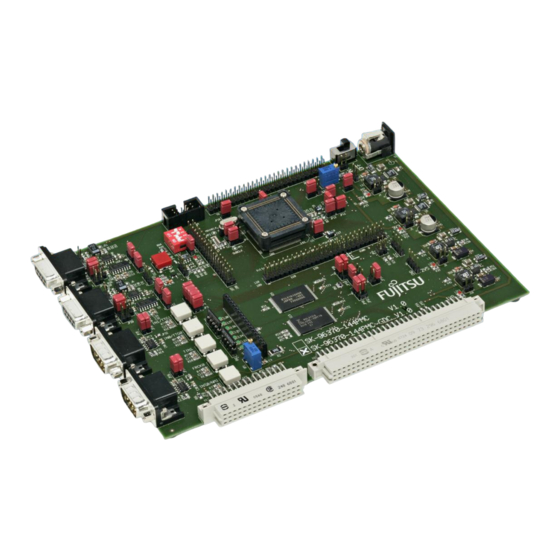
Chapter 1 Overview 1 Overview 1.1 Abstract The SK-96370-144PMC-GDC is a multifunctional evaluation board for the Fujitsu 16FX Flash microcontroller MB96370 Series. It can be used stand-alone for software development and testing or as a simple target board to work with the emulator system. -
Page 7: Features
1.2 Features < Supports Fujitsu’s 16FX MB96370 Series with 144 pin PMC / M08 package or the MB2198 Emulator System with the Probe Cable MB2198-507-E. < 9-15V unregulated external DC power supply < On-board 3.3V switching mode voltage regulator < Power-LEDs for all supply voltages <... -
Page 8: General Description
Eight user LEDs are connected to Port 09 and grounded by two 1k resistor networks (RN1, RN2). If these LEDs are not required, these resistor networks can be removed to disconnect the LEDs and to free the I/O port. FMEMCU-UG-960014-10 - 8 - © Fujitsu Microelectronics Europe GmbH... - Page 9 If the board is used as an emulator target board, the microcontroller must be removed from the socket and the corresponding probe cable has to be mounted: Series V-Chip Probe cable Socket NQPACK144SD-ND MB2198-507-E MB96370 MB96V300B HQPACK144SD Table 1-1: Emulation System © Fujitsu Microelectronics Europe GmbH - 9 - FMEMCU-UG-960014-10...
-
Page 10: Installation
Do not clean NQPACK, YQPACK, and YQSOCKET with steam. Cleaning material will contaminate inside of connector. FMEMCU-UG-960014-10 SK-96370-144PMC-GDC User Guide Chapter 2 Installation - 10 - © Fujitsu Microelectronics Europe GmbH... -
Page 11: Default Jumper Settings For Mb96370 Series
UART2 : DTR / RTS JP39 SOT2 : RS232 / LIN JP40 UART2 : RS232 / LIN JP41 UART Reset / Inverter © Fujitsu Microelectronics Europe GmbH SK-96370-144PMC-GDC User Guide Chapter 2 Installation Type Jumper 3 pin Jumper 4 pin Jumper 2 pin... - Page 12 Solder JP 2 pin Jumper 3 pin Solder JP 2 pin Solder JP 2 pin Solder JP 2 pin Jumper 2 pin Table 2-1: Jumper Settings - 12 - © Fujitsu Microelectronics Europe GmbH Default Coordinates Setting Open Open Open Closed...
-
Page 13: Jumper Location
2.3 Jumper Location The following picture shows the silk plot of the starter-kit with marked default jumper settings. Figure 2-1: Default Jumper Settings © Fujitsu Microelectronics Europe GmbH SK-96370-144PMC-GDC User Guide Chapter 2 Installation - 13 - FMEMCU-UG-960014-10... -
Page 14: Jumpers And Switches
OFF (open) ON (closed) OFF (open) ON (closed) OFF (open) MD0 MD1 MD2 nc MD0 MD1 MD2 nc - 14 - © Fujitsu Microelectronics Europe GmbH Logical value 1 (high) 0 (low) 1 (high) 0 (low) 1 (high) 0 (low) -
Page 15: Power Supply (S2, Jp: 8, 15, 16, 17, 22)
Table 3-2: Power Supply Configuration By default, all Board supplies are set to 3.3V. For SK-96370-144PMC-GDC use only 3.3V, because of the external memory © Fujitsu Microelectronics Europe GmbH SK-96370-144PMC-GDC User Guide Chapter 3 Jumpers and Switches and 3.3V supplies to the MCU... -
Page 16: Subclock (Jp: 1, 2)
Pin 68 is connected to GND (in case that subclock- device is used, but no 32 kHz crystal is connected) Pin 69 is connected to the 32 kHz sub-clock (X1A) Pin 69 is used as port pin P04_1 - 16 - © Fujitsu Microelectronics Europe GmbH... -
Page 17: Analog Power Supply Voltage (Jp: 11, 12, 13, 14)
JP78 One potentiometer can be connected to the ALARM0/AN8 Jumper Setting Closed JP85 (ALARM0) Open © Fujitsu Microelectronics Europe GmbH SK-96370-144PMC-GDC User Guide Chapter 3 Jumpers and Switches Description Closed AVcc is connected to Vcc Open AVcc is disconnected from Vcc... -
Page 18: Reset Generation (Jp: 33, 41, 46, 47, 48)
Reset is applied when SW6 is pressed > 2sec The voltage supply monitor observes 1V8 The voltage supply monitor observes 2V5 External reset generation is active Open No external reset generation Table 3-5: Reset Connection - 18 - © Fujitsu Microelectronics Europe GmbH... -
Page 19: User Buttons Sw1, Sw2, Sw3, Sw4, Sw5, Sw6 (Jp: 3, 4, 5, 6, 7)
(SDA0) Open Closed JP10 (SCL0) Open © Fujitsu Microelectronics Europe GmbH SK-96370-144PMC-GDC User Guide Chapter 3 Jumpers and Switches Description Pin 139 (INT0/NMI) of the MCU is connected to “SW1” No connection to the microcontroller Pin 19 (FRCK0) of the MCU is connected to “SW2”... -
Page 20: Lin / Uart
LIN-UART0 is LIN Master LIN-UART0 is LIN Slave LIN bus (X5 pin 1) is powered by the board LIN bus (X5 pin 1) is not powered by the board Table 3-7: UART0 Settings - 20 - © Fujitsu Microelectronics Europe GmbH... -
Page 21: Can Interfaces (Jp: 24, 26, 34, 35)
JP34 Closed (CAN1 RX) JP35 Closed (CAN1 TX) © Fujitsu Microelectronics Europe GmbH SK-96370-144PMC-GDC User Guide Chapter 3 Jumpers and Switches Description SIN2 is connected to RS232 transceiver SIN2 is connected to LIN transceiver SOT2 is connected to RS232 transceiver... -
Page 22: External Flash Memory (Jp: 49, 52, 56)
Address A22 of FLASH is connected to GND Description 16 bit data width 8 bit data width AD15 is connected (16 bit data width) A0 is connected (8 bit data width) Connect CS3 to the SRAM Disables the SRAM - 22 - © Fujitsu Microelectronics Europe GmbH... -
Page 23: Graphic Display Controller Interface (Jp: 54, 55, 56, 57, 58, 60, 85, 86)
Open (GLRST) Closed JP71 Open (FLRST) Closed Table 3-12: Graphic Display Controller interface © Fujitsu Microelectronics Europe GmbH SK-96370-144PMC-GDC User Guide Chapter 3 Jumpers and Switches support Graphic Display Description Address line A24 is floating Address line A24 is connected to GND... -
Page 24: Connectors
Ground normally used for RS232 connection Connected to DTR (pin 4) Can be connected with CTS by jumper Can be connected with RTS by jumper Ground normally used for LIN connection Ground - 24 - © Fujitsu Microelectronics Europe GmbH... -
Page 25: Can Connector (X6, X8)
CAN interfaces can be used simultaneously. Pin Number Pin Signal CANL CANH Shield Table 4-2: CAN Connector Signals © Fujitsu Microelectronics Europe GmbH SK-96370-144PMC-GDC User Guide Chapter 4 Connectors Figure 4-3: CAN Connector Description Not used LOW-level CAN voltage input/output... -
Page 26: User-Leds & Optional Lc-Display (J1)
Pin 15: Vcc via 39S/0.5W for LCD backlight FMEMCU-UG-960014-10 SK-96370-144PMC-GDC User Guide Chapter 4 Connectors Figure 4-4: User LEDs/LCD 09_0 09_1 09_2 09_3 Table 4-3: User LEDs/LCD - 26 - © Fujitsu Microelectronics Europe GmbH 9 10 DB4 DB5 DB6 09_4 09_5 09_6 09_7... -
Page 27: In-Circuit-Programming Connector (X4)
Figure 4-5: In-circuit programming connector Pin Number Pin Signal RSTX SIN3 SOT3 SCK3 Table 4-4: In-circuit programming connector © Fujitsu Microelectronics Europe GmbH SK-96370-144PMC-GDC User Guide Chapter 4 Connectors Description Not used Not used MCU mode pin MD0 Not used... -
Page 28: Alarm Comparator Connector (J2)
To this connector the INH pin of the LIN1 transceiver is connected. 4.15 VCC Connector (J7) On this connector the VCC supply (see chapter 3.2) can be measured. 4.16 GND Connector (J8) Ground reference terminal GND. FMEMCU-UG-960014-10 - 28 - © Fujitsu Microelectronics Europe GmbH... -
Page 29: Programming The Internal Flash Memory
(RS232/LIN) JP42 UART2 (Vbat) Table 5-2: Jumper Settings for Programming via UART 2 (X9) © Fujitsu Microelectronics Europe GmbH SK-96370-144PMC-GDC User Guide Setting Description SIN0 is connected to RxD of X5 SOT0 is connected to TxD of X5 RS232 transceiver is selected for X5... - Page 30 2) Connect the configured UART (see above) to your serial PC communication port. A straight 1:1 cable connection has to be used. 3) Start the tool “Fujitsu Flash MCU Programmer” software and make the settings: Set Device Type Select Crystal...
-
Page 31: Synchronous Mode
A dedicated Flash programming socket (X4) is provided on the evaluation-board for direct connection to this programmer. X4: Flash programming socket Figure 5-1: Flash Programming Socket © Fujitsu Microelectronics Europe GmbH SK-96370-144PMC-GDC User Guide MD0 MD1 MD2 nc n/c 1... -
Page 32: Appendix
(Tokyo Eletech Corp. www.tetc.co.jp/e_tet.htm) Socket header for package FPT-144P-M08 (LQFP-144) (Tokyo Eletech Corp. www.tetc.co.jp/e_tet.htm) Emulator probe cable for MB96F37x MCU MB96300 Series Evaluation chip Flash MCU (Single Clock) Flash MCU (Dual Clock) - 32 - © Fujitsu Microelectronics Europe GmbH... -
Page 33: Information In The Www
Datasheets and Hardware Manuals, Support Tools (Hard- and Software) http://mcu.emea.fujitsu.com/ Power Management Products http://www.fujitsu.com/emea/services/microelectronics/powerman/ Media Products: SAW filters, acoustic resonators and VCOs http://www.fujitsu.com/emea/services/microelectronics/saw/ For more information about FUJITSU MICROELECTRONICS http://www.fujitsu.com/emea/services/microelectronics/ © Fujitsu Microelectronics Europe GmbH SK-96370-144PMC-GDC User Guide Chapter 7 Information in the WWW - 33 -... -
Page 34: China-Rohs Regulation
“Year”. FMEMCU-UG-960014-10 - 34 - © Fujitsu Microelectronics Europe GmbH... - Page 35 SJ/T11363-2006. • Data listed in the table represents best information available at the time of publication © Fujitsu Microelectronics Europe GmbH SK-96370-144PMC-GDC User Guide Chapter 8 China-RoHS regulation...
-
Page 36: Recycling
According to the European WEEE-Directive and its implementation into national laws we take this device back. For disposal please send the device to the following address: Fujitsu Microelectronics Europe GmbH Warehouse/Disposal Monzastraße 4a 63225 Langen FMEMCU-UG-960014-10 - 36 - © Fujitsu Microelectronics Europe GmbH...
Need help?
Do you have a question about the MB96300 and is the answer not in the manual?
Questions and answers