Table of Contents
Advertisement
Quick Links
Please read this operation manual carefully for proper operation, and keep it
for future reference.
Note:
The model and serial numbers of your product are important for you to keep for
your convenience and protection. These numbers appear on the nameplate located on the
bottom of the product. Please record these numbers in the spaces provided below, and
retain this manual for future reference.
Model No.
Serial No.
Hitachi Denshi, Ltd.
3-CCD Color Camera
MODEL HV-D25
OPERATION MANUAL
5
Advertisement
Table of Contents

Related Manuals for Hitachi HV-D25


Summary of Contents for Hitachi HV-D25
- Page 1 3-CCD Color Camera MODEL HV-D25 OPERATION MANUAL Please read this operation manual carefully for proper operation, and keep it for future reference. Note: The model and serial numbers of your product are important for you to keep for your convenience and protection. These numbers appear on the nameplate located on the bottom of the product.
-
Page 2: Important Safety Instructions
IMPORTANT SAFETY INSTRUCTIONS 1. Read Instructions All the safety and operating instructions should be read before the product is operated. 2. Retain Instructions The safety and operating instructions should be retained for future reference. 3. Heed Warnings All warnings on the product and the operating instructions should be adhered to. 4. - Page 3 12. Grounding or Polarization This product is equipped with a three-wire grounding-type plug a plug having a third (grounding) pin. This plug will only fit into a grounding-type power outlet. This is a safety feature. If you are unable to insert the plug into the outlet, contact your electrician to replace your obsolete outlet.
- Page 4 amplifiers) that produce heat.
- Page 5 WICHTIGE SICHERHEITSANWEISUNGE 1. Alle Anweisungen lesen. Vor Betrieb des Erzeugnisses sollten alle Sicherheits-und Bedienungsanleitungen gelesen werden. 2. Die Anweisungen aufbewahren. Die Sicherheits-und Bedienungsanleitungen sollten fünftigen Bezug aufbewahrt werden. 3. Warnungen beachten. Die Warnungen auf dem Erzeugnis und in den Bedienungsanleitungen solten beachtet werden. 4.
- Page 6 11. Stromversorgung Dieses Erzeugnis sollte nur an der auf dem Typenschild angegebenen Stromversorgungsart betrieben werden. Wenn Sie nicht sicher sind, was für eine Stromversorgung Sie haben, so wenden Sie sich bitte an Ihren Erzeugnishändler oder an das lokale Elektrizitätswerk. Beziehen Sie sich für Batteriebetrieb oder andere Stromquellen vorgesehene Erzeugnisse bitte auf die Bedienungsanleitungen.
- Page 7 20. Beschädigung, die Wartung erfordert Ziehen Sie den Stecker dieses Erzeugnisses aus der Steckdose und wenden Sie sich an qualifiziertes Wartungspersonal, wenn eine der folgenden Bedingungen vorliegt: a. Wenn das Netzkabel oder der Stecker beschädigt ist. b. Bei Eindringen von Flüssigkeit oder Fremdkörpern in das Gerät. c.
- Page 8 MISES EN GARDE IMPORTANTES 1. Lire les instructions Lire toutes les instructions de sécurité et de fonctionnement avant de faire fonctionner l’appareil. 2. Conserver ces instructions Conserver les instructions de sécurité et de fonctionnement á des fins de référence ultérieure. 3.
- Page 9 12. Mise á la terre ou polarisation L’appareil est doté d’une fiche trifilaire avec mise á la terre, dont la troisiéme broche assure la mise á la terre. Cette fiche ne rentrera que dans les prises trifilaires de mise á la terre. Ceci est une mesure de sécurité. Si la fiche ne rentre pas dans la prise, faire remplacer la prise désuéte par un électricien.
- Page 10 21. Piéces de rechange Si l’on a besoin de piéces de rechange, veiller á ce que le technicien de réparation utilise exclusivement les piéces de rechange spécifiées par le fabricant ou des piéces ayant les mêmes caractéristiques que les piéces d’origine. Les piéces de rechange non autorisées risquent de provoquer un feu, un choc électrique et autres dangers.
-
Page 11: Important Notice
Operation of this product in a residential area is likely to cause harmful interference in which case the user will be required to correct the interference at his own expense. WARNING Changes or modifications not expressly approved by Hitachi Denshi responsible for compliance could void the user’s authority to operate the equipment. For Canada This product does not exceed the class A/class B limits for radio noise emissions from digital apparatus as set out in the radio interference regulations. -
Page 12: Table Of Contents
Table of contents l IMPORTANT SAFETY INSTRUCTUIONS ................ A l IMPORTANT NOTICE....................J l Table of contents......................K l Standard composition ....................1 l Overview ........................1 l Features ........................1 l Notes to users ......................2 Important safety notes....................2 Operating considerations...................2 CCD properties ......................3 l Rear panel facilities ......................5 l LENS...........................6 Lens selection ......................6... - Page 13 l Application files ......................31 l How to Attain Better images ..................33 Black Balance Adjustment..................33 White Balance Adjustment..................34 Real time Auto White....................36 Auto Shading Correction ..................36 ALC (Auto level control) ..................37 Lock scan mode shutter speed setting ..............38 Long-Time Store Mode.....................39 l Connection to RC-C10 remote control box ..............40 RC-C10 panel facilities ....................40 Menu screen operation ....................43...
-
Page 14: Standard Composition
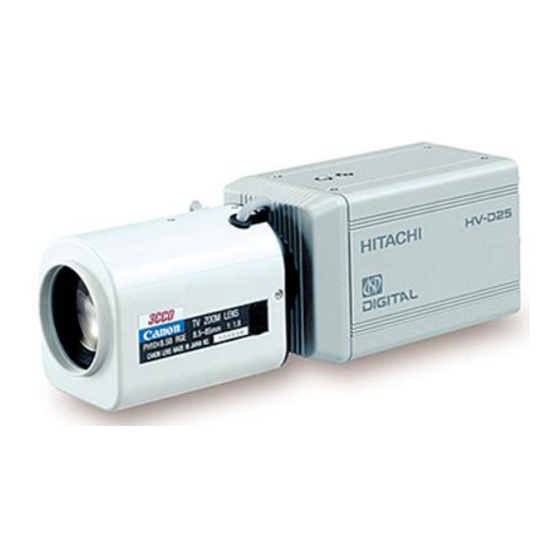
Overview HV-D25 is a 3 CCD color camera featuring advanced picture quality and high stability. Each 1/2-inch CCD has 410,000 (470,000 PAL) picture elements (pixels), while the circuits from processor to encoder are organized onto a single semiconductor chip. The precision C mount prism optics provide physical compatibility with a broad selection of general and special purpose lenses. -
Page 15: Notes To Users
Stop using the camera at the approach of an electrical storm (thunder audible). Protect the camera from rain if using it outdoors. l In event the camera shows any abnormality, switch off the camera and disconnect the power cord. Contact a Hitachi Denshi service representative. -
Page 16: Ccd Properties
Lens The correct lens is important for deriving optimum performance from the camera. Consult a Hitachi Denshi dealer for a selection of fine lenses according to the application. l Installation and storage sites The following types of environment can impair performance, lead to damage, pose safety hazards and shorten the useful life of the camera. - Page 17 3) Moire Interaction between patterns can produce an additional "phantom" pattern to appear. The CCD picture elements (pixels) are arranged in a pattern, which can interact with a pattern in the scene (e.g., a performer wearing a finely striped necktie) to result in a Moire pattern.
-
Page 18: Rear Panel Facilities
Rear panel facilities AWB/L button Direct mode (menu not displayed): Hold the button depressed for more than 2 seconds for auto white balance. Menu mode (menu displayed): Left direction button. Pilot lamp SETUP button VIDEO connector Press to display the camera setup menu. The direction (U, D, L, R) button Composite video signal output functions differ in the menu and direct... -
Page 19: Lens
Cosmicar). Lenses without self-contained iris amplifier are not compatible. Camera settings differ according to the auto iris lens type (see page 23). Note: The HV-D25 uses lens connector wiring prescribed by the EIAJ (Electronic Industries Association of Japan). Refer to page 48... -
Page 20: Flangeback Adjustment
Flangeback adjustment If focus cannot be adjusted after replacing the lens or at the telephoto and wide angle extremes of a zoom lens, the flangeback can be adjusted. Open the lens iris and adjust as described below. Fixed focus lens Set the lens focus ring to infinity and pickup an image more than 20 meters distant. - Page 21 2) Adjustment Hold the U button depressed and press Setup for about 2 seconds to display the Special Set menu. Change screen and check the Lens Type setting. If DC, change this to Video. to the Lens LENS (APP-1) LENS TYPE :VIDEO IRIS GAIN Video signal indicator...
-
Page 22: Camera Mounting
Camera mounting The camera is provided with threaded screw holes at the top and bottom. These allow mounting to either a tripod or a mounting bracket. Screw type ‚k U 1/4-20 Length: 4.5 to 6 mm Screws longer than 6 mm can cause internal damage, while less than 5 mm prevents secure fastening and risks dropping to cause damage and injury. -
Page 23: System Example
System examples Color monitor Surveillance and TV conferencing Lens Camera RC-C10 REMOTE Remote box DC IN Personal computer Lens remote unit RS-232C JU-C20 Level converter * A level converter is required if controlling the camra from a personal computer via RS-232C interface over a distance more then 15 meters. - Page 24 Microscope ststem Color monitor D-Sub 9pin DC IN REMOTE Remote control box RC-C10 Camera Personal computer Microscope AC Adaptor Computer image processing D-Sub 9pin Lens Camera Personal computer REMOTE DC IN AC Adaptor...
- Page 25 Multi-camera computer control Camera Color monitor Video Lens no.1 signal switcher REMOTE DC IN AC Adaptor Personal computer JU-Z2 Camera control box Camera Lens no.8 When using the JU-Z2 for multiple camera control, set REMOTE the camera internal SW405 to RC-C10. See page 34.
-
Page 26: Notes When Using Cables
Notes When Using Cables AUX Cable Use double shielded type cable. RC Cable As shown in the following figure, install clamp filter (ZCAT 2035-0530 : TDK) at camera end . Y/C Cable Use after winding a cable around a clamp filter (NTSC: ZCAT2035-0930 TDK) (PAL: ZCAT2436- 1330 TDK) once at camera end as shown in the following figure. -
Page 27: Menu Screen Operation
Menu Screen Operation 1. Menu Structure For settings in the camera, the MAIN and SPECIAL menus are available. 1-1 MAIN Menu Structure Press the SEUTP button and MAIN MENU appears on the screen to indicate the main menu mode. Again press the SETUP button to extinguish the menu and enter the direct mode. - Page 28 M HUE: 9 M SAT:- 2 SC COARSE : 0•‹ SC FINE INITIALIZE H PHASE DATA SET ID/TITLE :OFF :003 TITLE :OFF TITLE :HITACHI DATA SET :> 1234567890_? ABCDEFGHIJKL MNOPQRSTUVWX YZ<>+-*/.,:; EL INS RET GAMMA<ON> DTL<ON> GAMMA TABLE :STANDARD LEVEL DEP.
-
Page 29: Main Menu
2. MAIN MENU CAM MODE: Camera mode MANUAL : Nearly all function modes can be set. Use for detailed settings. AUTO : Video level and white balance are automatic and a standard picture cam be observed without detailed settings. Asterisk (*) indicates a fixed setting and the cursor jumps to the next item. The Auto indication flashes when a function is related to the auto mode. - Page 30 3) GAIN:Gain mode N O R M A L H I G H M A X A G C NORMAL:The gain level is set to 0 dB. HIGH: The gain level is set to a value specified at GAIN HIGH on the SUB menu 1. MAX: The gain level is set to a value specified at GAIN MAX on the SUB menu 1.
-
Page 31: Sub Menu 1
3. SUB MENU 1 1) M BLACK:Master black level setting The master black level can be set in a range of -128 to 127. Pressing the R button increases a set value to make the black level higher, and pressing the L button decreases a set value to make the black level lower. For zero (0) setting, hold down both the L and R buttons for approx. - Page 32 4)CCD MODE:CCD store mode changeover FLD: The field store mode operation is performed (for ordinary purpose of application). FRM:Frame store mode operation is performed. The vertical resolution can be increased but the degree of after-image becomes slightly higher. It is therefore recommended to use the FRM function when taking a still image.
-
Page 33: Sub Menu 2
4. SUB MENU 2 1) DYNA CHROMA:Dynamic chroma ON/OFF With knee on, setting the dynamic chroma on improves coloration in bright portions of the scene. 2) CHROMA GAIN:Level setting in chroma signal The chroma signal level can be set in the range of -128 to +127. Respectively press the R button to increase and the L button to decrease the chroma signal level. -
Page 34: Alc
10) WHITE GATE:White gate ON/OFF ON: In realtime auto white balance operation or execution of Window memory auto white balance, a video signal appearing in the window on screen is detected for white balancing. SUB MENU2 (APP-1) In the MENU mode, the window is presented over the DYNA CHROMA :OFF video signal. -
Page 35: Special Set
6. SPECIAL SET 1) REMOTE: Remote control baud rate setting For baud rate setting, use the L and R buttons. (Note) When setting a baud rate, do not connect the communication cable with the REMOTE terminal. 6 2 5 0 0 b p s 4 8 0 0 b p s 9 6 0 0 b p s 1 9 2 0 0 b p s... -
Page 36: Lens
7. LENS Menu for setting the lens functions 1) LENS Type: Sets type of auto iris. DC :Iris opens in proportion to a DC control voltage. Also set to DC when not using an automatic iris. Video: Lens iris is controlled by the video signal. (Note) Auto electronic shutter (AES) cannot be used in the Video mode. - Page 37 6) CLOSE Limit: (Lens Type is DC mode.) Observe the iris and adjust to precisely the largest value (smallest diameter). The setting range is from -128 to Close Limit -1. Press R to increase and L to decrease the setting. Press L and R buttons simultaneously for about 2 seconds to set to -85 for Cosmicar or to -65 for Others.
-
Page 38: Iris Gate
8. IRIS GATE This menu screen allows you to make iris gate (window) settings. 1) GATE AREA <UP/DOWN>:The window can be shifted up/down. To shift the window up, press the R button. To shift it down, press the L button. 2) GATE AREA<LEFT/RIGHT>:The window can be shifted left/right. -
Page 39: Masking
3) R GAIN: R gain level setting The allowable setting range is -128 to 127. Pressing the R button increases a numeric value to make the R video signal gain higher. Pressing the L button decreases a numeric value to lower the R video signal gain. For 0 (zero) setting, hold down both the L and R buttons for approx. -
Page 40: Output/Sync
139 INITIALIZE: Mask settings are initialized to factory values for each application file. Simultaneously press the L and R buttons for about 2 seconds to return the selected files to the factory settings. See Page 25 for the factory settings of each application file. 12 OUTPUT/SYNC On this menu screen, you can make signal changeover for output to the D-SUB connector and phase adjustment for external synchronization. -
Page 41: Id/Title
6) SC.COARSE:Coarse adjustment of subcarrier phase 0 • ‹ 9 0 • ‹ 1 8 0 • ‹ 2 7 0 • ‹ Using the L or R button, select one of the following phases; 0º, 90º, 180º and 270º. 7) SC.FINE:Fine adjustment of subcarrier phase The allowable setting range is -128 to 127. -
Page 42: Dtl
<ID/TITLE Setup Procedure> Œ With the cursor located at DATA SET, press the D button. The cursor moves to the ID data set position an the first character flashes. • Using the L, R, U and D buttons, select an input character. Ž... -
Page 43: Gamma
15. GAMMA Menu for setting the gamma parameters. If dark component contrast is inadequate, adjusting the gamma parameters allows detailed adjustment of the Sub-menu 2 Contrast (Off, Normal, High). 1) GAMMA TABLE: Sets gamma rising slope. Low:Dark component gradation reduced. Standard:Standard setting High:Dark component gradation increased. -
Page 44: Application Files
Application Files (APP-1,APP-2,APP-3) Camera setting data can be stored in three application files. These enable optimizing the camera for specific scene and lighting conditions, then storing the setting data in memory for quick recall at the appropriate time. The application files have been set at the factory as follows. APP-1: Standard type camera settings APP-2:... - Page 45 2. Com mon file settings The settings of these items apply to all files. They cannot be set differently for each file. The table indicates the factory settings. Menu item Setting data Menu item Setting data Menu item Setting data MAIN MENU SEPECIAL SET OUTPUT/SYNC...
-
Page 46: How To Attain Better Images
AUTO BLACK:NG Carry out ABB again. If this message appears in repeated attempts, it is necessary to inspect the inside of the camera. In this case, notify your local Hitachi Denshi sales TRY AGAIN agent or Hitachi Denshi service office... -
Page 47: White Balance Adjustment
White Balance Adjustment Carry out white balance adjustment when the illumination condition (color temperature) is changed. Adjust the white balance when using the camera for the first time or after replacing the lens. 1. In the MENU mode, set up WHITE BAL: MEM 3200K or MEM 5600K. 2. - Page 48 AUTO WHITE:NG Color temperature too high for optimum adjustment. C. TEMP HIGH Set WHITE BAL to MEM 5600 K mode. CHANGE TO MEM 5600K TRY AGAIN AUTO WHITE:NG Color temperature too low for optimum adjustment. C. TEMP LOW Set WHITE BAL to MEM 3200 K mode. CHANGE TO MEM 3200K TRY AGAIN AUTO WHITE:NG...
-
Page 49: Realtime Auto White
Realtime Auto White The camera detects a white part in the image by itself, and its internal microcomputer automatically adjusts white balance in realtime. Use this function in case that the color temperature varies with time (e.g., from morning to day to night). 1. -
Page 50: Alc (Auto Level Control)
In combination of GAIN:AGC, SHUTTER:AES and AUTO IRIS, the following four kinds of ALC (auto level control) can be performed. This feature ensures stable video signal output according to a wide-range change in illumination. Note: 1 AES cannot be combined with a Video type lens. 2 When not using an auto iris lens, at the Lens menu, set Lens Type to DC and Iris Mode to Manual. -
Page 51: Lock Scan Mode Shutter Speed Setting
Lock scan mode shutter speed setting 1 Press the Setup button and open the main menu, then open Sub menu 1. Set the cursor to SHUTTER by pressing D, select the VARIABLE position with the L-R buttons, again press D to shift to the variable items. 2 Press the L and R buttons to set the shutter speed in the range indicated below. -
Page 52: Long-Time Store Mode
Long-Time Store Mode In case that illumination on the subject is insufficient, just increasing the gain of the camera may cause an increase in noise, resulting in an unclear image. In such a situation, it is advisable to select the long-time store mode using the external memory. -
Page 53: Connection To Rc-C10 Remote Control Box
The HV-D25 camera can be remotely controlled from the RC-C10 remote control box. Adjustments and operations not provided on the RC-C10 panel can be set from the HV-D25 camera menu. RC-C10 buttons corresponding to the menu screen are Option 1, Option 2, Auto White and Auto Black. - Page 54 ABB/R (auto black balance/right) button Direct mode :Black balance is adjusted automatically. Menu mode :Execute or change function data. AWB/L (auto white balance/left) button Direct mode :White balance is adjusted automatically. Menu mode :Execute or change function data. Lock switch Left position :Genlock (GL) adjustment Right position...
- Page 55 Set button When pressed, control data are stored and the LED lights for about 1 second. l Notes: 1 Be sure to press the Set button in order to save the setting data before switching off power. Otherwise the data are lost and old data are returned at power on. Also, the old data are deleted by pressing the Set button.
-
Page 56: Menuscreenoperation
2.MenuscreenOperation Menu screen customizing Camera settings other than the RC-C10 panel can be customized at the Main and Special set menu screens. 2-1. Main menu screen Press the Setup button to produce the menu mode and display the main menu screen. Again press the Setup button extinguish the menu screen and produce the Direct mode. - Page 57 SC COARSE : 0•‹ SC FINE INITIALIZE H PHASE AWB/ AWB/ DATA SET ID/TITLE :OFF :003 TITLE :OFF TITLE :HITACHI DATA SET :> ABB/ 1234567890_? ABCDEFGHIJKL MNOPQRSTUVWX YZ<>+-*/.,:; DEL INS RET AWB/ AWB/ DTL<ON> LEVEL DEP. CRISP H/V BALANCE : 0...
-
Page 58: Application Files
3.Application files (APP-1, APP-2 and APP-3) The application files can be changed during remote control from the RC-C10. The HV-D25 camera is preset at the factory according to the application. APP-1:Standard camera settings APP-3:General surveillance, TV conference APP-3:Microscope setting. Masking is set for optimum color reproduction at color temperatures of 5000 light source and 9200 K color monitor. - Page 59 Common file settings are indicated below. Different settings for these items cannot be stored in the application files. The indicated data are for the factory settings. Notice there are some differences during local control of the HV-D25 camera. Menu items...
-
Page 60: Function Selection By Internal Switch Setting
Function Selection by Internal Switch Setting SW405 For connection with the remote control box RC-C10, set SW405 to the RC-C10 position. For connection with the personal computer, set SW405 to the RS-232C position. At shipment from factory, SW405 is set at the RC-C10 position. - Page 61 LENS connector AUX connector (HR10A-10R-12PB) Pin No. Signal Pin No. Signal designation +12V Control EXT CONT 1 EXT CONT 2 HD input VD input EXT CONT 3 EXT CONT 4 Y/C connector (TCS-7547-01-401) 12V-IN connector (RM12BRD-3PH) Pin No. Signal designation Pin No.
-
Page 62: Specifications
Specifications (1) Color system NTSC,PAL (2) Optical system 1/2-inch F1.6 prism (3) Imaging system RGB 3-chip (4) Imaging device 1/2-inch interline CCD (with microlenses) Total pixels NTSC: 811 (H) 508 (V) × PAL : 795 (H) 596 (V) × Effective pixels NTSC: 768 (H) 494 (V) ×... - Page 63 (19) CCD drive functions Preset 1/100 (1/60 PAL), 1/250, 1/500, 1/1,000, 1/2,000, 1/4,000, 1/10,000 second Lockscan NTSC: 1/60.38 to 1/251.5 second (1 H steps) PAL : 1/50.31 to 1/253.8 second (1 H steps) Off to approx. 1/1,000 second (up to equivalent of 4 F stops, continuously variable in 1 H steps) Long integration Selectable field/frame integration NTSC: 1/30 to approx.
-
Page 64: Input/Output Signals
Input/Output Signals 1. Input signal (1) Genlock input VBS 1.0 Vp-p 3 dB or black burst, 75 or high impedance (BNC) ± (Sync 0.3 0.1 Vp-p, burst 0.3 0.1 Vp-p) ± ± HD/VD TTL level (AUX connector) and 4.0 +0,-1Vp-p (2) Serial data (4 pin connector) 1.5 Vp-p 3 dB, high impedance (in connection with RC-C10) -
Page 65: Major Accessories
Major accessories Camera control box, RC-C10 Camera Junction box, JU-Z2 RS-232C level converter JU-C20... -
Page 66: Dimensions
Dimensions...
Need help?
Do you have a question about the HV-D25 and is the answer not in the manual?
Questions and answers