Table of Contents
Advertisement
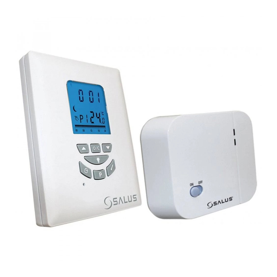
In st ru ct io n M a nu al
T105 RF
Selectable Volt Free
Warning - Please read this manual prior to
installation or use.
Shock Hazard
This unit must be installed by a competent person,
in accordance with BS 7671 (the IEE Wiring
Regulations), or other relevant national regulations
and codes of good practice.
Always isolate the AC Mains supply before removing
the unit from the Industry Standard Back Plate.
Manual Issue No. IM-T105VF-001
Advertisement
Table of Contents

Related Manuals for Salus T105 RF


Summary of Contents for Salus T105 RF
- Page 1 In st ru ct io n M a nu al T105 RF Selectable Volt Free Warning - Please read this manual prior to installation or use. Shock Hazard This unit must be installed by a competent person, in accordance with BS 7671 (the IEE Wiring Regulations), or other relevant national regulations and codes of good practice.
-
Page 2: Lcd
INTRODUCTION LCD : This thermostat can replace most common residential thermostat and is designed to be used with electric, gas or oil heating control system or cooling system. Unlike ordinary single unit design thermostat, This unit is a new type of thermostat separating the thermostat function into two units. -
Page 3: Features
Features : - 2 AA size alkaline batteries (no Several useful function and operating modes have - Slim housing design been incorporated to suit a variety of customer - EL backlight needs besides all the features associated with the Receiver: state of the art programmable thermostat. -
Page 4: Installation Of Receiver
- 2 AA size alkaline batteries (not included) 1. To adjust address code of Receiver, simp INSTALLATION OF RECEIVER push up one or more of the 5 dip switch n and operating modes have - Slim housing design Caution : levers. -
Page 5: Removing Old Thermostat
1. To adjust address code of Receiver, simply Push up one or WARNING: After removing the wall plate LLATION OF RECEIVER more of the push up one or more of the 5 dip switch find that it is mounted on a junction box (e white levers to adjust Receiver levers. -
Page 6: Choosing Location
WIRING DIAGRAM WARNING: After removing the wall plate, if you 4. Connect the wires - see wiring diagram. find that it is mounted on a junction box (e.g. a box 5. Push on the wires in the wall. FOR 230V APPLICATION similar to one behind a light switch or electric 6. - Page 7 WIRING DIAGRAM WIRING DIAGRAM s - see wiring diagram. SETTING OF CONTROL CENTR in the wall. FOR 230V APPLICATION FOR VOLT FREE APPLICATION Heater/Cooler Selection e Receiver to the wall with the (Remove Link!!!) Before making any selection in the The unit is default 230V, if volt free application is control centre, its back housing must required you must remove link &...
-
Page 8: Setting Of Control Centre
G DIAGRAM 20°C and span to 1°C, the heater will operate when SETTING OF CONTROL CENTRE Setting Clock the room temperature drops to 19.5°C and turns off OLT FREE APPLICATION Push and 1. Press the SET TIME button to Heater/Cooler Selection when the temperature rises to 20.5°C. -
Page 9: Setting Clock
C, the heater will operate when Setting Clock Setting Control Temperature ii) Select Control pro e drops to 19.5°C and turns off 1. Press the SET TIME button to clear all digits 1. Press the SET TEMPERATURE button to display the pre-defined re rises to 20.5°C. -
Page 10: Select Control Profile Pre-Defined
ol Temperature ii) Select Control profile 3. If any of these programs is selected, press the SET PROGRAM button again to confirm this PERATURE button to display the pre-defined program for the specified day and return to mperature. mode. 1. Press the SET PROGRAM button again, the day normal operation CON button to toggle between indicator stop flashing and the program number... -
Page 11: Testing Rf Transmission Range
TESTING THE RF TRANSMISSION Override the Setting Temperature 1. In the normal operation mode, the current set RANGE temperature can be overriden by pressing the UP 1. Press UP button until the setpoint temperature is or DOWN button. When in override, the new set higher than room temperature by a few degrees. -
Page 12: Battery Replacement
BACK- LIGHT LED INDICATOR There are two LEDs on the Power Control Unit as Press the BACK-LIGHT button to turn on the back- status indicators: light. The back-light will switch off when no button 1. Red LED turns on as long as there is power to the is pressed for 10 seconds.
Need help?
Do you have a question about the T105 RF and is the answer not in the manual?
Questions and answers