Qlogic SANbox2-16 Fibre Channel Installation Manual
Fibre channel switch
Hide thumbs
Also See for SANbox2-16 Fibre Channel:
- Supplementary manual (2 pages) ,
- Installation manual (228 pages) ,
- Installation manual (220 pages)
Table of Contents
Advertisement
Quick Links
Download this manual
See also:
Installation Manual
Advertisement
Table of Contents

Related Manuals for Qlogic SANbox2-16 Fibre Channel


Summary of Contents for Qlogic SANbox2-16 Fibre Channel
-
Page 1: Installation Guide
S i m p l i f y SANbox2-16 Fibre Channel Switch Installation Guide 59021-05 A Page i... -
Page 2: Document Revision History
QLogic Corporation reserves the right to change product specifications at any time without notice. Applications described in this document for any of these products are for illustrative purposes only. QLogic Corporation makes no representation nor warranty that such applications are suitable for the specified use without further testing or modification. -
Page 3: Table Of Contents
Table of Contents Section 1 Introduction Intended Audience ..................... 1-1 Related Materials ....................1-2 Safety Notices ....................1-3 Sicherheitshinweise.................... 1-3 Notes informatives relatives à la sécurité............1-3 Communications Statements................1-4 1.6.1 Federal Communications Commission (FCC) Class A Statement .... 1-4 1.6.2 Canadian Department of Communications Class A Compliance Statement ................ - Page 4 SANbox2-16 Fibre Channel Switch Installation Guide 2.2.2 Port LEDs ....................2-5 2.2.2.1 Logged-In LED ................. 2-6 2.2.2.2 Activity LED ..................2-6 2.2.3 Port Modes ....................2-6 2.2.3.1 Fabric Ports ..................2-7 2.2.3.2 Translated Loop Port ................ 2-7 2.2.3.3 Expansion Port ................. 2-7 Ethernet Port ......................
- Page 5 SANbox2-16 Fibre Channel Switch Installation Guide 4.2.3 Connect the Switch to AC Power .............. 4-5 4.2.4 Connect the Management Workstation to the Switch........ 4-8 4.2.4.1 Ethernet Connection ................. 4-9 4.2.4.2 Serial Connection ................4-9 4.2.5 Install SANbox Manager................4-10 4.2.6 SANsurfer Management Suite Disk - Windows Installation.....
- Page 6 SANbox2-16 Fibre Channel Switch Installation Guide 5.3.3 Maintenance – Reset Network Config ............. 5-14 5.3.4 Maintenance – Reset Password File ............5-14 5.3.5 Maintenance – Copy Log Files ..............5-14 5.3.6 Maintenance – Remove Switch Config............ 5-14 5.3.7 Maintenance – Remake Filesystem ............5-14 5.3.8 Maintenance –...
- Page 7 SANbox2-16 Fibre Channel Switch Installation Guide Set Command..................B-23 Set Config Command ................B-25 Set Log Command...................B-34 Set Port Command ..................B-37 Set Setup Command ................B-38 Show Command ..................B-42 Show Config Command................B-55 Show Log Command ................B-58 Show Perf Command ................B-60 Show Setup Command................B-62 Shutdown Command ................B-65 Test Command ..................B-66 Uptime Command..................B-69...
- Page 8 SANbox2-16 Fibre Channel Switch Installation Guide Chassis and Power Supply LEDs .................. 5-9 SFP Transceiver Installation ..................6-2 Power Supply Removal....................6-3 Fan Removal........................6-4 Fan Installation for Switch Model SB2A-16B ..............6-5 Tables Table Page Serial Port Pin Identification ................... 2-9 Port-to-Port Transmission Combinations ...............
-
Page 9: Introduction
Section 1 Introduction This manual describes the features and installation of the SANbox2-16 Fibre Channel switch, firmware version 1.5. This manual is organized as follows: Section 1 describes the intended audience, related materials, safety notices, communications statements, laser safety information, electrostatic discharge sensitivity precautions, accessible parts, and technical support. -
Page 10: Related Materials
1 – Introduction Related Materials Related Materials The following manuals and materials are referenced in the text and/or provide additional information. SANbox2-8c/16 Switch Management User’s Guide, Publication Number 59022-05. Fibre Channel-Arbitrated Loop (FC-AL-2) Rev. 6.8. Fibre Channel-Private Loop SCSI Direct Attach (FC-PLDA) NCITS TR-19:1998 Fibre Channel-10-bit Interface Rev. -
Page 11: Safety Notices
1 – Introduction Safety Notices Safety Notices A Warning notice indicates the presence of a hazard that has the potential of causing personal injury. 4-3, 4-5, A Caution notice indicates the presence of a hazard that has the potential of causing damage to the equipment. -
Page 12: Communications Statements
1 – Introduction Communications Statements Communications Statements The following statements apply to this product. The statements for other products intended for use with this product appear in their accompanying manuals. 1.6.1 Federal Communications Commission (FCC) Class A Statement This equipment has been tested and found to comply with the limits for a Class A digital device, pursuant to Part 15 of the FCC Rules. -
Page 13: Avis De Conformité Aux Normes Du Ministère Des Communications Du Canada
1 – Introduction Communications Statements 1.6.3 Avis de conformité aux normes du ministère des Communications du Canada Cet équipement ne dépasse pas les limites de Classe A d'émission de bruits radioélectriques por les appareils numériques, telles que prescrites par le Réglement sur le brouillage radioélectrique établi par le ministère des Communications du Canada. -
Page 14: Vcci Class A Statement
1 – Introduction Communications Statements 1.6.5 VCCI Class A Statement This is a Class A product based on the standard of the Voluntary Control Council For Interference by Information Technology Equipment (VCCI). If this equipment is used in a domestic environment, radio disturbance may arise. When such trouble occurs, the user may be required to take corrective actions. -
Page 15: Laser Safety Information
1 – Introduction Laser Safety Information Laser Safety Information This product may use Class 1 laser optical transceivers to communicate over the fiber optic conductors. The U.S. Department of Health and Human Services (DHHS) does not consider Class 1 lasers to be hazardous. The International Electrotechnical Commission (IEC) 825 Laser Safety Standard requires labeling in English, German, Finnish, and French stating that the product uses Class 1 lasers. -
Page 16: Accessible Parts
1 – Introduction Accessible Parts Accessible Parts The only Field Replaceable Units (FRUs) in the SANbox2-16 switch are: Small Form-Factor Pluggable (SFP) optical transceivers Power supplies Fans Refer to Section 6 Removal/Replacement for more information. 1.10 Pièces Accessibles Les pièces remplaçables, Field Replaceable Units (FRU), du commutateur SANbox2-16 Fibre Channel Switch sont les suivantes: Interfaces aux media d’interconnexion appelés SFP transceivers. -
Page 17: Technical Support
Contact Information for the latest firmware and software updates. 1.12.1 Availability QLogic Technical Support is available from 7:00 AM to 7:00 PM Central Standard Time, Monday through Friday, excluding QLogic-observed holidays. 1.12.2 Training QLogic offers the following technical training courses:... - Page 18 1 – Introduction Technical Support Notes 1-10 59021-05 A...
-
Page 19: Sanbox2-16 Fibre Channel Switch
Section 2 General Description This section describes the features and capabilities of the SANbox2-16 Fibre Channel switch. The following topics are described: Chassis controls and LEDs Fibre channel ports Ethernet port Serial port Power supplies Fans Fabric management Fabrics are managed with the SANbox Manager switch management application (version 1.05) and the Command Line Interface (CLI). -
Page 20: General Description Chassis Controls And Leds
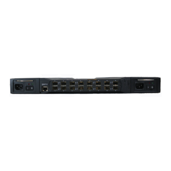
2 – General Description Chassis Controls and LEDs Chassis Controls and LEDs Chassis controls include the power supply On/Off switches and the Maintenance button as shown in Figure 2-2. The chassis LEDs include the Over Temperature LED, Fan Fail LED, Heartbeat LED, and the Input Power LED. Chassis LEDs Maintenance Button... -
Page 21: Chassis Leds
2 – General Description Chassis Controls and LEDs 2.1.3 Chassis LEDs The chassis LEDs shown in Figure 2-3 provide status information about switch operation. Refer to ”Power Supplies” on page 2-9 for information about power supply LEDs and to ”Port LEDs” on page 2-5 for information about port LEDs. -
Page 22: Heartbeat Led (Amber)
2 – General Description Fibre Channel Ports 2.1.3.3 Heartbeat LED (Amber) The Heartbeat LED indicates the status of the internal switch processor and the results of the Power On Self Test (POST). Following a normal power-up, the Heartbeat LED blinks about once per second to indicate that the switch passed the POST and that the internal switch processor is running. -
Page 23: Small Form-Factor Pluggable (Sfp) Transceivers
2 – General Description Fibre Channel Ports 2.2.1 Small Form-Factor Pluggable (SFP) Transceivers An SFP transceiver, like the one shown in Figure 2-5, converts electrical signals to and from optical laser signals to transmit and receive data. SFP transceivers plug into the ports;... -
Page 24: Logged-In Led
2 – General Description Fibre Channel Ports 2.2.2.1 Logged-In LED The Logged-in LED indicates the logged-in or initialization status of the connected devices. After successful completion of the POST, the switch extinguishes all Logged-In LEDs. Following a successful loop initialization or port login, the switch illuminates the corresponding logged-in LED. -
Page 25: Fabric Ports
2 – General Description Fibre Channel Ports G_Ports self-configure in the following ways: F_Port when connected to a public device E_Port when connected to another FC-SW-2 compliant switch A TL_Port supports private loop devices and must be configured explicitly. Refer to the SANbox2-8c/16 Switch Management User’s Guide for more information about defining port modes. -
Page 26: Ethernet Port
2 – General Description Ethernet Port Ethernet Port The Ethernet port shown in Figure 2-7 is an RJ-45 connector that provides a connection to a management workstation. A management workstation can be a Windows, Solaris™ workstation, or a Linux® workstation that is used to configure and manage the switch fabric. -
Page 27: Power Supplies
2 – General Description Power Supplies The serial port connector requires a null-modem F/F DB9 cable. The pins on the switch RS-232 connector are shown in Figure 2-8 and identified in Table 2-1. Refer to ”Connect the Management Workstation to the Switch” on page 4-8 information about connecting the management workstation through the serial port. -
Page 28: Fans
2 – General Description Fans Each power supply is capable of providing all of the switch’s power needs. During normal operation, each power supply provides half of the demand. If one power supply goes offline, the second power supply steps up and provides the difference. -
Page 29: Switch Management
2 – General Description Switch Management Switch Management SANbox Manager is a workstation-based Java® application that provides a graphical user interface for fabric management. This application runs on a Windows®, Solaris™, or Linux® workstation. The management workstation connects to the fabric directly through one switch’s Ethernet port and provides in-band management for all other switches in the fabric. - Page 30 2 – General Description Switch Management Notes 2-12 59021-05 A...
-
Page 31: Planning
Section 3 Planning Consider the following when planning a fabric: Devices Multiple chassis fabrics Performance Device access Fabric management Fabric security Devices When planning a fabric, consider the number of devices and the anticipated demand. This will determine the number of ports that are needed and in turn the number of switches. -
Page 32: Multiple Chassis Fabrics
3 – Planning Multiple Chassis Fabrics Multiple Chassis Fabrics By connecting switches together you can expand the number of available ports for devices. Each switch in the fabric is identified by a unique domain ID, and the fabric will automatically resolve domain ID conflicts. Because the ports are self-configuring, you can connect SANbox2-16 and other FC-SW-2 compliant switches together in a wide variety of topologies. -
Page 33: Common Topologies
3 – Planning Multiple Chassis Fabrics 3.2.2 Common Topologies This section describes three commonly used topologies: Cascade Mesh Multistage® 3.2.2.1 Cascade Topology A cascade topology describes a fabric in which the switches are connected in a linear fashion. If you connect the last switch back to the first switch, you create a cascade-with-a-loop topology as shown in Figure 3-1. -
Page 34: Mesh Topology
3 – Planning Multiple Chassis Fabrics 3.2.2.2 Mesh Topology A mesh topology describes a fabric in which each chassis has at least one port directly connected to each other chassis in the fabric. The example mesh fabric shown in Figure 3-2 has the following characteristics: Each link contributes up to 200 MB/s of bandwidth between switches, 400 MB/s in full duplex. -
Page 35: Multistage Topology
3 – Planning Multiple Chassis Fabrics 3.2.2.3 Multistage Topology A Multistage topology describes a fabric in which two or more edge switches connect to one or more core switches. Each additional core switch increases the bandwidth to each edge switch by 200 MB/s. The Multistage fabric shown in Figure 3-3 has the following characteristics: Each link contributes up to 200 MB/s of bandwidth between chassis. -
Page 36: Performance
3 – Planning Performance Performance The SANbox2-16 switch supports class 2 and class 3 Fibre Channel service at transmission rates of 1 Gbps or 2 Gbps with a maximum frame size of 2148 bytes. A port can transmit or receive at 1 Gbps or 2 Gbps depending on the device to which it is connected. -
Page 37: Bandwidth
3 – Planning Performance 3.3.2 Bandwidth Bandwidth is a measure of the volume of data that can be transmitted at a given transmission rate. A port can transmit or receive at 1 Gbps or 2 Gbps depending on the device to which it is connected. The switch supports all transmission rate combinations as shown in Table 3-1. -
Page 38: Device Access
3 – Planning Device Access Device Access Consider device access needs within the fabric. Access is controlled by the use of zones and zone sets. Some zoning strategies include the following: Separate devices that use different operating systems. Separate devices that have no need to communicate with other devices in the fabric or have classified data. -
Page 39: Soft Zones
3 – Planning Device Access 3.4.1 Soft Zones Soft zoning divides the fabric for purposes of controlling discovery. Members of the same soft zone automatically discover and communicate freely with all other members of the same zone. The soft zone boundary is not secure; traffic across soft zones can occur if addressed correctly. -
Page 40: Virtual Private Fabric Hard Zones
3 – Planning Fabric Management 3.4.3 Virtual Private Fabric Hard Zones Virtual Private Fabric (VPF) zoning divides the fabric for purposes of controlling discovery and both inbound and outbound traffic. This type of zoning is useful for providing security and reserving paths between devices to guarantee bandwidth. VPF zoning is a type of hard zoning that is hardware enforced. -
Page 41: Fabric Security
3 – Planning Fabric Security Fabric Security You manage fabric security on a switch basis through the creation of user accounts. Each account consists of an account name, a password, and an authority level. There are two authority levels: User and Admin. These authority levels apply to SANbox Manager and to the CLI. - Page 42 3 – Planning Fabric Security Notes 3-12 59021-05 A...
-
Page 43: Installation
Section 4 Installation This section describes how to install and configure the SANbox2-16 switch. It also describes how to load new firmware and how to recover a disabled switch. Site Requirements The following items are required for the installation of a SANbox2-16 switch: Fabric management workstation Power requirements Environmental conditions... -
Page 44: Environmental Conditions
4 – Installation Installing a Switch 4.1.3 Environmental Conditions Consider the factors that affect the climate in your facility such as equipment heat dissipation and ventilation. The switch requires the following operating conditions: Operating temperature range: 10° to 40° C (50°- 104°F) Relative humidity: 25 - 80%, non-condensing Installing a Switch Unpack the switch and accessories. -
Page 45: Mount The Switch
The top of each chassis has dimples to receive the rubber feet of a second chassis stacked on top. Without the rubber feet, the switch occupies 1U of space in an EIA rack. Mounting rails are required and available through QLogic Corporation. -
Page 46: Install Sfp Transceivers
4 – Installation Installing a Switch To mount the switch in a rack, do the following: Ensure that the19-inch rack meets the following standard specifications: ANSI/EIA RS-230 Standard, entitled Cabinets, Racks, Panels, and Associated Equipment MIL-STD- 189, entitled Racks, Electrical Equipment, 19-Inch and Associated Panels Mount the brackets on the front or rear corners of the chassis as shown in Figure... -
Page 47: Connect The Switch To Ac Power
4 – Installation Installing a Switch 4.2.3 Connect the Switch to AC Power WARNING!! This product is supplied with a 3-wire power cable and plug for the user’s safety. Use this power cable in conjunction with a properly grounded outlet to avoid electrical shock. An electrical outlet that is not correctly wired could place hazardous voltage on metal parts of the switch chassis. - Page 48 4 – Installation Installing a Switch WARNUNG!! Dieses Produkt wird mit einem 3-adrigen Netzkabel mit Stecker geliefert. Dieses Kabel erfüllt die Sicherheitsanforderungen und sollte an einer vorschriftsmäßigen Schukosteckdose angeschlossen werden, um die Gefahr eines elektrischen Schlages zu vermeiden.Elektrosteckdosen, die nicht richtig verdrahtet sind, können gefährliche Hochspannung an den Metallteilen des switch-Gehäuses verursachen.
- Page 49 4 – Installation Installing a Switch Confirm that the Output Power LEDs on both power supplies are illuminated. If not, do the following: Check voltage at the AC power source. Inspect the power cord. Replace the power supply. Observe the Heartbeat LED to determine the results of the Power On Self Test (POST).
-
Page 50: Connect The Management Workstation To The Switch
4 – Installation Installing a Switch 4.2.4 Connect the Management Workstation to the Switch Connect the management workstation to the switch in one of three ways: Indirect Ethernet connection from the management workstation to the switch RJ-45 Ethernet connector through an Ethernet switch or a hub. This requires a 10/100 Base-T straight cable as shown in Figure 4-3. -
Page 51: Ethernet Connection
4 – Installation Installing a Switch 4.2.4.1 Ethernet Connection To establish an Ethernet connection, do the following: Connect a 10/100 Base-T cross-over cable from an RJ-45 port on the management workstation directly to the RJ-45 Ethernet port; or a 10/100 Base-T straight cable indirectly over an Ethernet network. -
Page 52: Install Sanbox Manager
4 – Installation Installing a Switch For Linux: Set up minicom to use the serial port. Create or modify the /etc/minirc.dfl file with the following content: pr portdev/ttyS0 pu minit pu mreset pu mhangup Verify that all users have permission to run minicom. Review the /etc/minicom/users file and confirm that the line "ALL"... -
Page 53: Sansurfer Management Suite Disk - Windows Installation
4 – Installation Installing a Switch 4.2.6 SANsurfer Management Suite Disk - Windows Installation To install the SANbox Manager application on Windows from the SANsurfer® Management Suite Disk, do the following: Close all programs currently running, and Insert the SANsurfer Management Suite Disk into the management workstation CD-ROM drive. -
Page 54: Sansurfer Management Suite Disk - Linux Installation
4 – Installation Installing a Switch 4.2.7 SANsurfer Management Suite Disk - Linux Installation To install the SANbox Manager application on Linux from the SANsurfer Management Suite Disk, do the following: Close all programs currently running, and insert the SANsurfer Management Suite Disk into the management workstation CD-ROM drive. -
Page 55: Sansurfer Management Suite Disk - Solaris Installation
4 – Installation Installing a Switch 4.2.8 SANsurfer Management Suite Disk - Solaris Installation To install the SANbox Manager application on Solaris from the SANsurfer Management Suite CD-ROM, do the following: Close all programs currently running, and insert the SANsurfer Management Suite Disk into the management workstation CD-ROM drive. -
Page 56: Sanbox2 Installation Disk - Windows Installation
4 – Installation Installing a Switch 4.2.9 SANbox2 Installation Disk - Windows Installation To install the SANbox Manager application on Windows from the SANbox2 Installation Disk, do the following: Close all programs currently running, and insert the SANbox2 Installation Disk into the management workstation CD-ROM drive. Using Windows Explorer, double-click the drive letter which contains the SANbox2 Installation Disk. -
Page 57: Configure The Switch
4 – Installation Installing a Switch 4.2.12 Configure the Switch Do the following to configure a switch using the SANbox Manager application. Refer to the SANbox2-8c/16 Switch Management User’s Guide for more information about configuring a switch. You can also configure the switch using the Command Line Interface. -
Page 58: Configure The Ports
4 – Installation Installing a Switch 4.2.13 Configure the Ports Configuring a port involves defining the port mode. For public devices and other switches, a switch automatically sets the port mode as each port discovers the type of device to which it is connected. A GL_Port will self configure as an FL_Port when connected to a loop of public devices or an F_Port when connected to a single device. -
Page 59: Install Firmware
4 – Installation Install Firmware Install Firmware The switch comes with current firmware installed. You can upgrade the firmware from the management workstation as new firmware becomes available. Firmware installation involves loading the firmware image file onto the switch, unpacking the image file, and then resetting the switch to activate the new firmware. -
Page 60: Using The Cli To Install Firmware
4 – Installation Install Firmware 4.3.2 Using the CLI to Install Firmware To install firmware using the CLI when an FTP server is present on the management workstation, do the following: Connect to the switch through the Ethernet or the serial port and open a Telnet session. -
Page 61: Using Ftp And The Cli To Install Firmware
4 – Installation Install Firmware 4.3.3 Using FTP and the CLI to Install Firmware To install firmware using the CLI when the management workstation does not have an FTP server, do the following: Connect to the switch through the Ethernet or the serial port. Move to the folder or directory that contains the new firmware image file. -
Page 62: Powering Down A Switch
4 – Installation Powering Down a Switch Display the list of firmware image files on the switch to confirm that the file was loaded. Refer to the ”Image Command” on page B-13 for more information. cli (admin) $>image list Unpack the firmware image file to install the new firmware in flash memory. cli (admin) $>image unpack filename Reset the switch to activate the new firmware. -
Page 63: Diagnostics/Troubleshooting
Section 5 Diagnostics/Troubleshooting Diagnostic information about the switch is available through the chassis LEDs, the power supply LEDs, and the port LEDs. Diagnostic information is also available through the SANbox Manager and CLI event logs and error displays. This section describes two types of diagnostics: Power On Self Test (POST) and chassis. -
Page 64: Maintenance Mode Pattern
5 – Diagnostics/Troubleshooting POST Diagnostics 5.1.1.2 Maintenance Mode Pattern Steady illumination indicates that the switch is in maintenance mode, which returns the switch IP address to 10.0.0.1. From maintenance mode, you may reload firmware, reset the password to the factory default, and remove a corrupt configuration. - Page 65 5 – Diagnostics/Troubleshooting POST Diagnostics Place the switch in maintenance mode. Press and hold the Maintenance button, then power up the switch. Refer to ”Recovering a Switch” on page 5-12 for more information about placing the switch in maintenance mode. Establish a Telnet session with the switch using the default IP address 10.0.0.1.
- Page 66 5 – Diagnostics/Troubleshooting POST Diagnostics Activate binary mode and copy the configuration file from the workstation to the switch. The configuration file must be named "configdata". ftp>bin ftp>put configdata Close the FTP session. ftp>quit Establish communications with the switch using Telnet. Enter one of the following on the command line: telnet xxx.xxx.xxx.xxx telnet switchname...
-
Page 67: Logged-In Led Indications
5 – Diagnostics/Troubleshooting POST Diagnostics 5.1.2 Logged-In LED Indications Port diagnostics are indicated by the Logged-In LED for each port as shown in Figure 5-1. Logged-In LED Figure 5-1. Port Logged-In LED The Logged-In LED has three indications: Logged in - Continuous illumination. Logging in - Flashes at roughly once per second as shown in Figure 5-2. -
Page 68: E_Port Isolation
5 – Diagnostics/Troubleshooting POST Diagnostics 5.1.2.1 E_Port Isolation A Logged-In LED error indication is often the result of E_Port isolation. An isolated E_Port is indicated by a red link in the SANbox Manager topology display. E_Port isolation can be caused by conflicting domain IDs, conflicting timeout values, or conflicting zone membership between active zone sets. -
Page 69: Excessive Port Errors
5 – Diagnostics/Troubleshooting POST Diagnostics 5.1.2.2 Excessive Port Errors The switch monitors a set of port errors and generates alarms based on user-defined sample intervals and thresholds. Refer to the SANbox2-8c/16 Switch Management User’s Guide for information about managing alarms. These port errors include the following: CRC errors Decode errors... - Page 70 5 – Diagnostics/Troubleshooting POST Diagnostics Reset the port, then perform an external port loopback test to validate the port and the SFP. Refer to the ”Test Command” on page B-66 or the SANbox2-8c/16 Switch Management User’s Guide for information about testing ports.
-
Page 71: Chassis Diagnostics
5 – Diagnostics/Troubleshooting Chassis Diagnostics Chassis Diagnostics Chassis diagnostics are indicated by the chassis and power supply LEDs as shown in Figure 5-3. Chassis Over Output Power LED Temperature LED Fan Fail LED Power Supply Over Input Power LED Temperature LED Figure 5-3. -
Page 72: Chassis Over Temperature Led Is Illuminated
5 – Diagnostics/Troubleshooting Chassis Diagnostics 5.2.1 Chassis Over Temperature LED is Illuminated The chassis Over Temperature LED illuminates to indicate that the switch logic circuitry is overheating. If the chassis Over Temperature LED illuminates, do the following: Inspect the chassis fans. Are the intake openings clear? Are both fans operating and producing air flow? Yes - Continue. -
Page 73: Output Power Led Is Extinguished
5 – Diagnostics/Troubleshooting Chassis Diagnostics 5.2.4 Output Power LED Is Extinguished The Output Power LED illuminates to indicate that the power supply is producing the proper voltages. If the Output Power LED is extinguished, do the following: Inspect the power supply Over Temperature LED. Is the power supply Over Temperature LED illuminated? Yes - Refer to ”Power Supply Over Temperature LED is Illuminated”... -
Page 74: Recovering A Switch
5 – Diagnostics/Troubleshooting Recovering a Switch Recovering a Switch A switch can become inoperable or unavailable for the following reasons: Firmware becomes corrupt IP address is lost Switch configuration becomes corrupt Forgotten password In these specific cases, you can recover the switch using maintenance mode. Maintenance mode temporarily returns the switch IP address to 10.0.0.1 and provides opportunities to do the following: Unpack a firmware image file... -
Page 75: Maintenance - Exit
5 – Diagnostics/Troubleshooting Recovering a Switch The maintenance menu displays several recovery options. To select a switch recovery option, press the corresponding number (displayed in option: field) on the keyboard and press the Enter key. Exit Image Unpack Reset Network Config Reset Password File Copy Log Files Remove Switch Config... -
Page 76: Maintenance - Reset Network Config
5 – Diagnostics/Troubleshooting Recovering a Switch 5.3.3 Maintenance – Reset Network Config This option resets the network properties to the factory default values and saves them on the switch. Refer to Table B-6 for the default network configuration values. 5.3.4 Maintenance –... - Page 77 Section 6 Removal/Replacement This section describes the removal and replacement procedures for the following field replaceable units (FRU): SFP transceivers Power supplies Fans The switch is equipped with a battery that powers the non-volatile memory. This memory stores the switch configuration. The battery is not a field replaceable unit. WARNING!! Danger of explosion if battery is incorrectly replaced.
-
Page 78: Removal/Replacement Sfp Transceivers
6 – Removal/Replacement SFP Transceivers SFP Transceivers The SFP transceivers can be removed and replaced while the switch is operating without damaging the switch or the transceiver. However, transmission on the affected port will be interrupted until the transceiver installed. To remove a transceiver, gently press the transceiver into the port to release the tension, then pull on the release tab or lever and remove the transceiver. -
Page 79: Power Supply Removal
6 – Removal/Replacement Power Supplies Power Supplies The power supplies are hot pluggable. This means you can remove or install one of the power supplies while the switch is operating without disrupting service. The power supplies are also interchangeable; that is, the left and right power supplies are the same unit. -
Page 80: Fans
6 – Removal/Replacement Fans Fans The fans are hot pluggable. This means you can remove or install one of the fans while the switch is operating without disrupting service. The fan is completely enclosed, so there is no risk of injury from the fan blades. The fans are also interchangeable;... -
Page 81: Fan Installation For Switch Model Sb2A-16B
6 – Removal/Replacement Fans To install a fan, do the following: Confirm that the new fan is compatible with the switch air flow direction. Align the modular connector toward the inside of the switch as shown in Figure 6-4. Slide the fan into the bay until it is firmly seated and confirm that the air flow is correct. - Page 82 6 – Removal/Replacement Fans Notes 59021-05 A...
-
Page 83: Appendix A Specifications
Appendix A Specifications Appendix A contains the specifications for the SANbox2-16 Fibre Channel switch. Refer to Section 2 General Description for the location of all connections, switches, controls, and components. Switch Specifications Fibre Channel Protocols ....FC-PH Rev. 4.3 FC-PH-2 FC-PH-3 FC-AL Rev 4.5 FC-AL-2 Rev 7.0... -
Page 84: Switch Maintainability
A – Specifications Switch Maintainability Maximum User Ports ...... > 475,000 ports depending on configuration Buffer Credits........12 buffer credits per port Media Type ........Small Form Pluggable (SFP) optical transceivers. Hot swappable. 3.3 Volts. Fabric Port Speed ......1.0625 or 2.125 Gigabits/second Maximum Frame Size..... -
Page 85: Fabric Management
A – Specifications Fabric Management Fabric Management Management Methods ....SANbox Manager application Command Line Interface GS-3 Management Server SNMP Maintenance Connection ....RS-232 connector; null modem F/F DB9 cable Ethernet Connection ....... RJ-45 connector; 10/100BASE T cable Switch Agent........Allows a network management station to obtain configuration values, traffic information, and failure data pertaining to the Fibre Channels via SNMP through the... -
Page 86: Switch Environmental
A – Specifications Switch Environmental Switch Environmental Temperature Operating ........10 to 40°C (50 to 104°F) Non-operating ......-40 to 65°C (-40 to 149°F) Humidity Operating ........25% to 80%, non-condensing Non-operating ......25% to 90%, non-condensing Altitude Operating ........0 to 3048m (0 to 10,000 feet) Non-operating ...... -
Page 87: Shortwave Laser Sfp 1G/2G (Multi-Mode
A – Specifications Shortwave Laser SFP 1G/2G (multi-mode) Shortwave Laser SFP 1G/2G (multi-mode) Connector ........Duplex LC Color coding........Beige or black exposed connector surfaces Cable ..........Fibre Channel 100-M6-SN-I (50 µm multimode) Fibre Channel 200-M5-SN-I or 200-M6-SN-I (62.5 µm multimode) Wavelength........ -
Page 88: Longwave Laser Sfp 1G/2G (Single-Mode
A – Specifications Longwave Laser SFP 1G/2G (single-mode) Longwave Laser SFP 1G/2G (single-mode) Connector ........Duplex LC Color coding........Blue exposed connector surfaces Cable ..........Fibre Channel 100SM-LC-L (9 µm single mode) Wavelength........1270 - 13.5 nm Transmit Power....... -10 dBm minimum Receiver Sensitivity ...... -
Page 89: Appendix B Command Line Interface
Appendix B Command Line Interface Each switch contains a Telnet server. This server allows a Telnet client to establish a Telnet session with the switch to retrieve information or to configure parameters using the Command Line Interface (CLI). The CLI enables you to perform a variety of fabric and switch management tasks through an Ethernet or a serial port connection. -
Page 90: Command Syntax
B – Command Line Interface Command Syntax Command Syntax The command syntax is as follows: command keyword keyword [value] keyword [value1] [value2] The Command is followed by one or more keywords. Consider the following rules and conventions: Commands and keywords are lowercase and case sensitive. Commands with keywords require one of those keywords. -
Page 91: Commands
B – Command Line Interface Commands Commands The command set provides for User and Admin authority levels. User authority grants viewing access to the fabric and switches using the Show command and other read-only commands. Admin authority includes the User authority and grants permission to use the Admin command. -
Page 92: Admin Command
B – Command Line Interface Admin Command Admin Command Opens and closes an Admin session. The Admin session provides commands that change the fabric and switch configurations. Only one Admin session can be open on the switch at any time. An inactive Admin session will time out after a period of time which can be changed using the Set Setup System command. -
Page 93: Alias Command
B – Command Line Interface Alias Command Alias Command Creates a named set of ports/devices. Aliases make it easier to assign a set of ports/devices to many zones. An alias can not have a zone or another alias as a member. - Page 94 B – Command Line Interface Alias Command members [alias] Displays all members of the alias given by [alias]. This keyword is available with User authority and does not require a zoning edit session or an admin session. remove [alias] [members] Removes the ports given by [members] from the alias given by [alias].
-
Page 95: Config Command
B – Command Line Interface Config Command Config Command Manages the Fibre Channel configurations on a switch. For information about setting the port and switch configurations, refer to the Set Config Command on page B-25. Authority Admin for all keywords except List Syntax config activate [config]... - Page 96 B – Command Line Interface Config Command restore Restores configuration settings to an out-of-band switch from a backup file named configdata, which must be first uploaded on the switch using FTP. You create the backup file using the Config Backup command. Use FTP to load the backup file on a switch, then enter the Config Restore command.
-
Page 97: Date Command
B – Command Line Interface Date Command Date Command This command displays or sets the system date and time. To set the date and time the information string must be provided in this format: MMDDhhmmCCYY. You must reset the switch for the new date to take effect. Authority Admin to change the date;... -
Page 98: Fallback Command
B – Command Line Interface Fallback Command Fallback Command Loads the fallback version of the firmware from switch memory. The switch stores two versions of the firmware. This command alternately activates the two versions. Authority Admin Syntax fallback Notes The Show Switch command displays the available firmware versions and the currently active version. -
Page 99: Help Command
B – Command Line Interface Help Command Help Command Displays a brief description of the specified command and its keywords. Authority User Syntax help [command] [keyword] Keywords [command] Displays a summary of the command given by [command] and its keywords. If you omit [command], the system displays all available commands from which to choose. -
Page 100: History Command
B – Command Line Interface History Command History Command Displays a numbered list of the previously entered commands from which you can re-execute selected commands. Authority User Syntax history Notes Use the History command to provide context for the ! command: Enter ![command] to re-enter the most recent execution of that command. -
Page 101: Image Command
B – Command Line Interface Image Command Image Command Manages and installs switch firmware. Authority Admin Syntax image cleanup fetch [account_name] [ip_address] [file_source] [file_destination] list unpack [file] Keywords cleanup Removes all firmware image files from the switch. All firmware image files are removed automatically each time the switch is reset. -
Page 102: Lip Command
B – Command Line Interface Lip Command Lip Command Reinitializes the specified loop port. Authority Admin Syntax lip [port_number] Keywords [port_number] The number of the port to be reinitialized. Examples The following is an example of the Lip command: SANbox2 (admin) #>... -
Page 103: Passwd Command
B – Command Line Interface Passwd Command Passwd Command Changes a user account’s password. Authority Admin to change another account’s password; User to change your own. Syntax passwd [account_name] Keywords [account_name] The user account name. You must open an admin session to change the password for an account name other than your own. -
Page 104: Ps Command
B – Command Line Interface Ps Command Ps Command Displays current system process information. Authority User Syntax Examples The following is an example of the Ps command: SANbox2 #> ps PPID %CPU TIME ELAPSED COMMAND 0.0 00:00:00 59:42 0.0 00:00:00 59:42 0.0 00:00:00 59:42 dlog 0.3 00:00:53 59:42... -
Page 105: Quit Command
B – Command Line Interface Quit Command Quit Command Closes the Telnet session. Authority User Syntax quit, exit, or logout 59021-05 A B-17... -
Page 106: Reset Command
B – Command Line Interface Reset Command Reset Command Resets the switch and port configuration parameters. Authority Admin Syntax reset config [config_name] factory port [port_number] snmp switch (default) system zoning Keywords config [config_name] Resets the configuration given by [config_name] to the factory default values for switch, port, alarm threshold, and zoning configuration. -
Page 107: B-2 Switch Configuration Defaults
B – Command Line Interface Reset Command Table B-2. Switch Configuration Defaults Parameter Default Admin State Online Broadcast Enable True InbandEnable True Domain ID Domain ID Lock False Symbolic Name SANbox2 R_T_TOV R_A_TOV 10000 E_D_TOV 2000 FS_TOV 5000 DS_TOV 5000 Principal Priority System Description Undefined... -
Page 108: B-4 Alarm Threshold Configuration Defaults
B – Command Line Interface Reset Command Table B-3. Port Configuration Defaults (Continued) Parameter Default ExtCredit FanEnable True LCFEnable False MFSEnable True MFS_TOV MSEnable True NoClose False IOStreamGuard Disabled VIEnable False CheckAlps False Table B-4. Alarm Threshold Configuration Defaults Parameter Default ThresholdMonitoringEnabled False... -
Page 109: B-5 Snmp Configuration Defaults
B – Command Line Interface Reset Command Table B-4. Alarm Threshold Configuration Defaults (Continued) Parameter Default LogoutMonitoringEnabled True RisingTrigger FallingTrigger SampleWindow LOSMonitoringEnabled True RisingTrigger FallingTrigger SampleWindow Table B-5. SNMP Configuration Defaults Parameter Default Contact Undefined Location Undefined Description Undefined Trap [1-5] Address Trap 1: 10.0.0.254;... -
Page 110: B-6 System Configuration Defaults
B – Command Line Interface Reset Command Table B-6. System Configuration Defaults Parameter Default Ethernet Network IP Address 10.0.0.1 Ethernet Network IP Mask 255.0.0.0 Ethernet Gateway Address 10.0.0.254 Ethernet Network Discovery Static Admin Timeout 30 minutes SecurityEnabled False LocalLogEnabled True RemotelogEnabled False RemoteLogHostIPAddress... -
Page 111: Set Command
B – Command Line Interface Set Command Set Command Sets a variety of switch and port parameters. Authority Admin for all keywords except Alarm Clear, Beacon, and Pagebreak which are available with User authority. Syntax alarm clear beacon [state] config [option] log [option] pagebreak [state] port [option]... - Page 112 B – Command Line Interface Set Command port [option] Sets port state and speed for the specified port temporarily until the next switch reset or new configuration activation. Refer to the ”Set Port Command” on page B-37. setup [option] Changes SNMP and system configuration settings. Refer to the ”Set Setup Command”...
-
Page 113: Set Config Command
E_Port security. Determines which switches a port will establish a link with. Any - link with any FC-SW-2 compliant switch. Ours - link only with an FC-SW-2 compliant QLogic switch. None - reject the link. SymbolicPortName Descriptive name 59021-05 A... - Page 114 B – Command Line Interface Set Config Command Table B-7. Set Config Port Parameters (Continued) Parameter Description ALFairness Arbitration loop fairness. Enables (True) or disables (False) the switch’s priority to arbitrate on the loop. ARB_FF Use ARB_FF instead of idles on loop FCAL option InteropCredit Interoperability credit.
-
Page 115: B-8 Set Config Switch Parameters
B – Command Line Interface Set Config Command switch Initiates an editing session in which to change switch configuration settings. The system displays each parameter one line at a time and prompts you for a value. For each parameter, enter a new value or press the Enter key to accept the current value shown in brackets. -
Page 116: B-9 Set Config Threshold Parameters
B – Command Line Interface Set Config Command Table B-8. Set Config Switch Parameters (Continued) Parameter Description PrincipalPriority The priority used in the FC-SW-2 principal switch selection algorithm. 1 is high, 255 is low. ConfigDescription The name for the configuration. The default is undefined. -
Page 117: B-10 Set Config Zoning Parameters
B – Command Line Interface Set Config Command Table B-9. Set Config Threshold Parameters (Continued) Parameter Description Rising Trigger The event count above which a rising threshold alarm is logged. The switch will not generate another rising threshold alarm for that event until the count descends below the falling threshold and again exceeds the rising threshold. - Page 118 B – Command Line Interface Set Config Command Examples The following is an example of the Set Config Port command: SANbox2 #> admin start SANbox2 (admin) #> config edit SANbox2 (admin-config) #> set config port 1 A list of attributes with formatting and current values will follow. Enter a new value or simply press the ENTER key to accept the current value.
- Page 119 B – Command Line Interface Set Config Command The following is an example of the Set Config Switch command: SANbox2 #> admin start SANbox2 (admin) #> config edit SANbox2 (admin-config) #> set config switch A list of attributes with formatting and default values will follow. Enter a new value or simply press the ENTER key to accept the current value.
- Page 120 B – Command Line Interface Set Config Command RisingTrigger (decimal value, 1-1000) [200 ] FallingTrigger (decimal value, 0-1000) [0 ] SampleWindow (decimal value, 1-1000 sec) [10 ] ISLMonitoringEnabled (True / False) [True] RisingTrigger (decimal value, 1-1000) [2 ] FallingTrigger (decimal value, 0-1000) [0 ] SampleWindow (decimal value, 1-1000 sec) [10 ]...
- Page 121 B – Command Line Interface Set Config Command The following is an example of the Set Config Zoning command. SANbox2 #> admin start SANbox2 (admin) #> config edit SANbox2 (admin-config) #> set config zoning A list of attributes with formatting and current values will follow. Enter a new value or simply press the ENTER key to accept the current value.
-
Page 122: Set Log Command
B – Command Line Interface Set Log Command Set Log Command Specifies the type of entries to be entered in the event log. The log is a storage file contained on the switch. The log can hold a maximum of 200 entries. When the log becomes full, the entries are replaced, starting with the oldest entry, to produce a list of the last 200 events which occurred. - Page 123 B – Command Line Interface Set Log Command Other Monitors other miscellaneous events. Port Monitors all port events Switch Monitors switch management events. Zoning Monitors zoning conflict events. level [level] Specifies the severity level given by [level] to use in monitoring events for the specified components or ports.
- Page 124 B – Command Line Interface Set Log Command start Starts the logging of events based on the Port, Component, and Level keywords assigned to the current configuration. The logging continues until you enter the Set Log Stop command. stop Stops logging of events. Notes To maintain optimal switch performance, do not set the Component keyword to All and the Level keyword to Info at the same time.
-
Page 125: Set Port Command
B – Command Line Interface Set Port Command Set Port Command Sets port state and speed for the specified port temporarily until the next switch reset or new configuration activation. This command also clears port counters. Authority Admin Syntax set port [port_number] bypass [alpa] clear enable... -
Page 126: Set Setup Command
B – Command Line Interface Set Setup Command Set Setup Command Changes SNMP and system configuration settings. The switch maintains one SNMP configuration and one system configuration. Authority Admin Syntax set setup snmp system Keywords snmp Prompts you in a line-by-line fashion to change SNMP configuration settings. Table B-11 describes the SNMP fields. -
Page 127: B-12 System Configuration Settings
B – Command Line Interface Set Setup Command Table B-11. SNMP Configuration Settings Entry Description TrapCommunity Trap community password that authorizes an SNMP agent to receive traps. This is a write-only field. The value on the switch and the SNMP management server must be the same. - Page 128 B – Command Line Interface Set Setup Command Notes The two components of security are user authentication and fabric security. The user must be authenticated before gaining access to a switch. If an invalid account name/password combination is entered, that user can not access the switch, and thus can not gain access to the fabric.
- Page 129 B – Command Line Interface Set Setup Command Trap5Severity (see allowed options above) [warning Trap5Enabled (True / False) [False ReadCommunity (string, max=32 chars) [public WriteCommunity (string, max=32 chars) [private TrapCommunity (string, max=32 chars) [public AuthFailureTrap (True / False) [False Do you want to save and activate this snmp setup? (y/n) [n] The following is an example of the Set Setup System command: SANbox2 (admin) #>...
-
Page 130: Show Command
B – Command Line Interface Show Command Show Command Displays fabric, switch, and port operational information. Authority User Syntax show about alarm broadcast chassis config [option] domains donor fabric interface log [option] lsdb mem [count] ns [option] pagebreak perf [option] port [port_number] post log setup [option]... - Page 131 B – Command Line Interface Show Command domains Displays list of each domain and its worldwide name in the fabric. donor Displays list of current donor configuration for all ports. fabric Displays list of each domain, fabric ID, worldwide name, node IP address, and port IP address.
-
Page 132: B-13 Show Port Parameters
B – Command Line Interface Show Command perf [option] Displays performance information for all ports. Refer to the Show Perf Command on page B-60. port [port_number] Displays operational information for the port given by [port_number]. Ports are numbered beginning with 0. If the port number is omitted, information is displayed for all ports. - Page 133 B – Command Line Interface Show Command Table B-13. Show Port Parameters (Continued) Entry Description LIPF7F7 A loop initialization primitive frame used to acquire a valid AL_PA. LIPF8F7 A loop initialization primitive frame used to indicate that a loop failure has been detected at the receiver. Link Failures Number of optical link failures detected by this port.
- Page 134 B – Command Line Interface Show Command Table B-13. Show Port Parameters (Continued) Entry Description TotalTxWords Total number of words issued by this port. TxLinkResets Number of Link Resets issued by this port. TxOfflineSeq Total number of Offline Sequences issued by this port. TxWait Time waiting to transmit when blocked with no credit.
- Page 135 B – Command Line Interface Show Command Zoneset (Active, List) Zoning (History, Limits, List) switch Displays switch operational information. topology Displays all connected devices. users Displays a list of logged-in users. This is equivalent to the User List command. version Displays an introductory set of information about operational attributes of the switch.
- Page 136 Show Command The following is an example of the Show Setup SNMP command: SANbox2 #> show setup snmp SNMP Information ---------------- Contact Technical Support Location TSLab Description QLogic SANbox2 FC Switch Trap1Address 10.20.71.15 Trap1Port Trap1Severity warning Trap1Enabled True Trap2Address 0.0.0.0...
- Page 137 B – Command Line Interface Show Command The following is an example of the Show NS Domain_ID command: SANbox2 #> show ns domain_ID Port ID: 630425 -------- PortType PortWWN 21:00:00:20:37:d9:4b:2a SymbolicPortName NodeWWN 20:00:00:20:37:d9:4b:2a SymbolicNodeName NodeIPAddress 0.0.0.0 ClassOfService PortIPAddress 0.0.0.0 FabricPortName 20:04:00:c0:dd:00:b7:ea FC4Type FC4Desc...
- Page 138 B – Command Line Interface Show Command The following is an example of the Show Port command: SANbox2 #> show port 1 Port Number: 1 ------------ AdminState Online PortID 640100 AsicNumber PortWWN AsicPort RunningType Donor ConfigType Donor SFPPartNumber PL-XPL-00-S23-00 DiagStatus Passed SFPRevision EpConnState...
- Page 139 B – Command Line Interface Show Command The following is an example of the Show Setup System command: SANbox2 (admin) #> show setup system System Information ------------------ Eth0NetworkAddress 10.20.11.112 Eth0NetworkMask 255.255.252.0 Eth0GatewayAddress 10.20.8.254 Eth0NetworkDiscovery Static AdminTimeout SecurityEnabled True LocalLogEnabled True RemoteLogEnabled True RemoteLogHostAddress...
- Page 140 B – Command Line Interface Show Command The following is an example of the Show Switch command: SANbox2 #> show switch Switch Information ------------------ SymbolicName SANbox2-203 SwitchWWN 10:00:00:c0:dd:00:b8:b5 SwitchType SANbox2-16 PromVersion V0.1-5-18 (Fri Jun 15 10:22:09 2001) CreditPool DomainID LogLevel Info MaxPorts NumberOfAsics...
- Page 141 B – Command Line Interface Show Command The following is an example of the Show Topology command for port 1: SANbox2 #> show topology 1 Local Link Information ---------------------- PortNumber 1 PortID 650100 PortWWN 20:01:00:c0:dd:00:91:11 PortType Remote Link Information ----------------------- Device 0 NodeWWN 50:80:02:00:00:06:d5:38 PortType NL...
- Page 142 B – Command Line Interface Show Command The following is an example of the Show Version command: SANbox2 #> show version SystemDescription QLogic SANbox2 FC Switch Eth0NetworkAddress 10.0.0.1 (use ’set setup system’ to update) FCNetworkAddress 0.0.0.0 (use ’set setup system’ to update) MACAddress...
-
Page 143: Show Config Command
B – Command Line Interface Show Config Command Show Config Command Displays switch, port, alarm threshold, and zoning attributes for the current configuration. Authority User Syntax show config port [port_number] switch threshold zoning Keywords port [port_number] Displays configuration parameters for the port number given by [port_number]. Ports are numbered beginning with 0. - Page 144 E_D_TOV 2000 FS_TOV 5000 DS_TOV 5000 PrincipalPriority ConfigDescription QLogic SANbox2 FC Switch ConfigLastSavedBy guest@IB-session10 ConfigLastSavedOn Mon Nov 18 15:10:03 2002 The following is an example of the Show Config Threshold command: SANbox2 #> show config threshold Configuration Name: default ------------...
- Page 145 B – Command Line Interface Show Config Command FallingTrigger SampleWindow ISLMonitoringEnabled True RisingTrigger FallingTrigger SampleWindow LoginMonitoringEnabled True RisingTrigger FallingTrigger SampleWindow LogoutMonitoringEnabled True RisingTrigger FallingTrigger SampleWindow LOSMonitoringEnabled True RisingTrigger FallingTrigger SampleWindow The following is an example of the Show Config Zoning command: SANbox2 #>...
-
Page 146: Show Log Command
B – Command Line Interface Show Log Command Show Log Command Displays the contents of the log or the parameters used to create entries in the log. The log contains a maximum of 200 entries. When the log reaches its entry capacity, subsequent entries overwrite the existing entries, beginning with the oldest. - Page 147 B – Command Line Interface Show Log Command The following is an example of the Show Log Options command: SANbox2 #> show log options Allowed options for ’ level’: Critical,Warn,Info,None Allowed options for ’component’: All,None,NameServer,MgmtServer,Zoning,Switch, Chassis,Blade,Port,Eport,Snmp,Other The following is an example of the Show Log command: [327][Wed Jan 25 09:36:54.860 1989][I][Eport:0xdd00b8b6.304.4 Port: 0/8][Eport State = E_A0_GET_DOMAIN_ID] [328][Wed Jan 25 09:36:54.860 1989][I][Eport:0xdd00b8b6.304.4 Port: 0/8][FSPF...
-
Page 148: Show Perf Command
B – Command Line Interface Show Perf Command Show Perf Command Displays port performance in frames/second and bytes/second. If you omit the keyword, the command displays data transmitted (out), data received (in), and total data transmitted and received in frames/second and bytes per second. Authority User Syntax... - Page 149 B – Command Line Interface Show Perf Command Examples The following is an example of the Show Perf command: SANbox2 #> show perf Port Bytes/s Bytes/s Bytes/s Frames/s Frames/s Frames/s Number (in) (out) (total) (in) (out) (total) ------ ------- ------- ------- -------- --------...
-
Page 150: Show Setup Command
The following is an example of the Show Setup Mfg command: SANbox2 #> show setup mfg Manufacturing Information ------------------------- BoardSerialNumber 000781428 BrandName QLogic BuildDate Unknown ChassisPartNumber Unknown ChassisSerialNumber S01450034 MACAddress 00:c0:dd:00:bc:09 PlanarPartNumber Unknown SwitchSymbolicName SANbox2 SwitchWWN 10:00:00:c0:dd:00:bc:08 SystemDescription QLogic SANbox2 FC Switch SystemObjectID 1.3.6.1.4.1.1663.1.1.1.1.11 B-62 59021-05 A... - Page 151 The following is an example of the Show Setup Snmp command: SANbox2 #> show setup snmp SNMP Information ---------------- Contact <sysContact undefined> Location N_107 System Test Lab Description QLogic SANbox2 FC Switch Trap1Address 10.0.0.254 Trap1Port Trap1Severity warning Trap1Enabled False Trap2Address 0.0.0.0...
- Page 152 B – Command Line Interface Show Setup Command The following is an example of the Show Setup System command: SANbox2 #> show setup system System Information ------------------ Eth0NetworkAddress 10.0.0.1 Eth0NetworkMask 255.255.255.0 Eth0GatewayAddress 10.0.0.254 Eth0NetworkDiscovery Static AdminTimeout SecurityEnabled False LocalLogEnabled True RemoteLogEnabled False RemoteLogHostAddress...
-
Page 153: Shutdown Command
B – Command Line Interface Shutdown Command Shutdown Command Terminates all data transfers on the switch at convenient points and closes the Telnet session. Always power cycle the switch after entering this command. Authority Admin Syntax shutdown Notes Always use this command to effect an orderly shut down before removing power from the switch. -
Page 154: Test Command
B – Command Line Interface Test Command Test Command Tests ports using internal (SerDes level), external (SFP), and online loopback tests. Internal and external tests require that the port be placed in diagnostic mode. Refer to the ”Set Command” on page B-23 for information about changing the port administrative state. - Page 155 B – Command Line Interface Test Command To run an external loopback test, enter the following command. A loopback plug must be installed for this test to pass. test x external A series of test parameters are displayed on the screen. Press the Enter key to accept each default parameter value, or type a new value for each parameter and press the Enter key.
- Page 156 B – Command Line Interface Test Command A series of test parameters are displayed on the screen. Press the Enter key to accept each default parameter value, or type a new value for each parameter and press the Enter key. The TestLength parameter is the number of frames sent, the FrameSize (256 byte maximum in some cases) parameter is the number of bytes in each frame, and the DataPattern parameter is the pattern in the payload.
-
Page 157: Uptime Command
B – Command Line Interface Uptime Command Uptime Command Displays the elapsed time since the switch was last reset and reset method. Authority User Syntax uptime Examples The following is an example of the Uptime command: SANbox2 #> uptime Elapsed up time : 0 day(s), 2 hour(s), 28 min(s), 44 sec(s) Reason last reset: NormalReset 59021-05 A... -
Page 158: User Command
B – Command Line Interface User Command User Command Administers or displays user accounts. Authority Admin. The List keyword is available with User authority. Syntax user accounts delete [account_name] list Keywords accounts Displays all user accounts that exist on the switch. Add a user account to the switch. - Page 159 B – Command Line Interface User Command The following is an example of the User Add command: SANbox2 (admin) #> user add Press ’q’ and the ENTER key to abort this command. account name (1-15 chars) : user3 account password (4-20 chars) please confirm account password: should this account have admin authority? (y/n) [n] : y OK to add user account ’user3’...
-
Page 160: Whoami Command
B – Command Line Interface Whoami Command Whoami Command Displays the account name, session number, and switch domain ID for the Telnet session. Authority User Syntax whoami Examples The following is an example of the Whoami command: SANbox2 #> whoami User name:admin@session2 Switch name:SANbox2 Switch domain ID:1... -
Page 161: Zone Command
B – Command Line Interface Zone Command Zone Command Manages zones and zone membership on a switch. The Zone command defines members (ports/devices) for a single switch. Zones are members of zone sets. Authority Admin authority and a Zoning Edit session. Refer to the Zoning Command on page B-80 for information about starting a Zoning Edit session. - Page 162 B – Command Line Interface Zone Command list Displays a list of all zones and the zone sets of which they are members. This keyword is valid for User authority and does not require a zoning edit session. members [zone] Displays all members of the zone given by [zone].
- Page 163 B – Command Line Interface Zone Command Examples The following is an example of the Zone List command: SANbox2 #> zone list Zone ZoneSet ------------------- wwn_b0241f zone_set_1 wwn_23bd31 zone_set_1 wwn_221416 zone_set_1 wwn_2215c3 zone_set_1 wwn_0160ed zone_set_1 wwn_c001b0 zone_set_1 wwn_401248 zone_set_1 wwn_02402f zone_set_1 wwn_22412f zone_set_1...
- Page 164 B – Command Line Interface Zone Command The following is an example of the Zone Zonesets command: SANbox2 #> zone zonesets zone1 Current List of ZoneSets for Zone: wwn_b0241f ---------------------------------- zone_set_1 B-76 59021-05 A...
-
Page 165: Zoneset Command
B – Command Line Interface Zoneset Command Zoneset Command Manages zone sets and zone set membership across the fabric. Authority Admin authority and a Zoning Edit session. Refer to the Zoning Command on page B-80 for information about starting a Zoning Edit session. The Active, List, and Zones keywords are available with User authority. - Page 166 B – Command Line Interface Zoneset Command delete [zone_set] Deletes the zone set given by [zone_set]. If the specified zone set is active, the command is suspended until the zone set is deactivated. This keyword requires a Zoning Edit session. list Displays a list of all zone sets.
- Page 167 B – Command Line Interface Zoneset Command The following is an example of the Zoneset Zones command: SANbox2 #> zoneset zones ssss Current List of Zones for ZoneSet: ssss ---------------------------------- zone1 zone2 zone3 59021-05 A B-79...
-
Page 168: Zoning Command
B – Command Line Interface Zoning Command Zoning Command Opens a Zoning Edit session in which to create and manage zone sets and zones. Refer to the Zone Command on page B-73 and the Zoneset Command on page B-77. Authority Admin. - Page 169 B – Command Line Interface Zoning Command list Lists all fabric zoning definitions. This keyword is available with User authority. restore Reverts the changes to the zoning database that have been made during the current Zoning Edit session since the last Zoning Save command was entered. save Saves changes made during the current Zoning Edit session.
- Page 170 B – Command Line Interface Zoning Command 50:06:04:82:bf:d2:18:c2 50:06:04:82:bf:d2:18:d2 10:00:00:00:c9:22:14:16 wwn_2215c3 50:06:04:82:bf:d2:18:c2 50:06:04:82:bf:d2:18:d2 10:00:00:00:c9:22:15:c3 Configured Zoning Information ZoneSet Zone ZoneMember -------------------------------- wwn_b0241f 50:06:04:82:bf:d2:18:c2 50:06:04:82:bf:d2:18:d2 21:00:00:e0:8b:02:41:2f wwn_23bd31 50:06:04:82:bf:d2:18:c2 50:06:04:82:bf:d2:18:d2 10:00:00:00:c9:23:bd:31 wwn_221416 50:06:04:82:bf:d2:18:c2 50:06:04:82:bf:d2:18:d2 10:00:00:00:c9:22:14:16 wwn_2215c3 50:06:04:82:bf:d2:18:c2 50:06:04:82:bf:d2:18:d2 10:00:00:00:c9:22:15:c3 B-82 59021-05 A...
-
Page 171: Glossary
Glossary Activity LED ARB_FF A port LED that indicates when frames are When ARB_FF is enabled, it causes the entering or leaving the port. switch to send the ARB_FF primitive when it is in monitoring mode, rather than idles. Alias The only reason to do this is since the ARB_FF has less bit transitions than does A collection of objects that can be zoned... - Page 172 Memory on the switch that contains the link with any switch. Ours - we will only link chassis control firmware. to another QLogic switch. None - the port will not establish an ISL link. Frame Data unit consisting of a start-of-frame...
-
Page 173: Logged-In Led Indications
SANbox2-16 Fibre Channel Switch Installation Guide Over Temperature LED Logged-In LED A port LED that indicates device login or A chassis LED or a power supply LED that loop initialization status. indicates that the switch or power supply is overheating. Management Information Base POST A set of guidelines and definitions for the... - Page 174 SANbox2-16 Fibre Channel Switch Installation Guide SNMP Simple Network Management Protocol Target A storage device that responds to an initiator device. VCCI Voluntary Control Council for Interference VIEnable FC-VI. When enabled, VI preference frames will be transmitted ahead of other frames.
- Page 175 Index Numerics brackets 4-2, 4-4 broadcast B-42 10/100 Base-T straight cable 4-8 buffer credit 3-6, A-2 access 3-8 cable Access Control List zone 3-9 10/100 Base-T 4-8 account name 10/100 Base-T crossover cable 4-8 description 3-11 fibre optic 3-1 display B-72 null modem F/F DB9 4-8 ftp 5-3 cascade topology 3-3...
- Page 176 SANbox2-16 Fibre Channel Switch Installation Guide management workstation 4-1 point-to-point bandwidth A-2 Date command B-9 ports 2-7 device security 3-11, 4-10 cabling 4-16 factory defaults 5-14, B-18 description 3-1 Fallback command B-10 diagnostics 5-1, 5-9, A-2 Fan Fail LED 2-3, 5-10 dimensions A-3 fans 2-10, 6-4 distance 3-6...
- Page 177 SANbox2-16 Fibre Channel Switch Installation Guide Help command B-11 History command B-12 maintainability A-2 host bus adapter 3-1 maintenance humidity 4-2, A-4 blink pattern 5-2 HyperTerminal application 4-9 exit 5-13 interface A-3 menu 5-13 Image command B-13 mode 2-2, 5-2, 5-12 immunity A-4 strategy A-2 initiator device 2-7...
- Page 178 SANbox2-16 Fibre Channel Switch Installation Guide file reset 5-14 Ps command B-16 maintenance mode 5-12 restore default 5-14 switch 3-11, B-15 Quit command B-17 user account B-1 performance 3-6 planning 3-1 rack mount 4-3 port recovering a switch 5-12 administrative state B-37 regulatory certifications A-4 buffer credits 3-6 remake filesystem 5-14...
- Page 179 SANbox2-16 Fibre Channel Switch Installation Guide SNMP See - Simple Network Management user Protocol account 3-11, B-1 soft zone 3-9 authority 3-11, B-3 steering B-46 interface A-2 switch logged in B-47 administrative state B-24 User command B-70 configuration 4-15, B-27 configuration display B-55 initialize B-18 ventilation 2-10...
- Page 180 SANbox2-16 Fibre Channel Switch Installation Guide create B-77 deactivate B-18, B-77 delete B-78 delete member zone B-78 display B-78 display active B-77 display members B-78 display zones B-74 rename B-78 Zoneset command B-77 zoning configuration B-29 configuration display B-55 database 3-8, B-18 edit B-80 history B-80 limits 3-8, B-80...
Need help?
Do you have a question about the SANbox2-16 Fibre Channel and is the answer not in the manual?
Questions and answers